

Page 1

www.proform.com
Model No. PFEX02909.2
Serial No.
Write the serial number in the
space above for reference.
Serial Number
Decal
QUESTIONS?
If you have questions, or if parts are
damaged or missing, DO NOT
CONTACT THE STORE; please
contact Customer Care.
IMPORTANT: Please register this
product (see the limited warranty
on the back cover of this manual)
before contacting Customer Care.
USERʼS MANUAL
CALL TOLL-FREE:
1-888-533-1333
Mon.–Fri. 6 a.m.–6 p.m. MT
Sat. 8 a.m.–4 p.m. MT
ON THE WEB:
www.proformservice.com
CAUTION
Read all precautions and instructions in this manual before using
this equipment. Keep this manual
for future reference.
Page 2

TABLE OF CONTENTS
WARNING DECAL PLACEMENT . . . . . . . . . . . . . . . . . . . . . . . . . . . . . . . . . . . . . . . . . . . . . . . . . . . . . . . . . . . . . .2
MPORTANT PRECAUTIONS . . . . . . . . . . . . . . . . . . . . . . . . . . . . . . . . . . . . . . . . . . . . . . . . . . . . . . . . . . . . . . . .3
I
BEFORE YOU BEGIN . . . . . . . . . . . . . . . . . . . . . . . . . . . . . . . . . . . . . . . . . . . . . . . . . . . . . . . . . . . . . . . . . . . . . .4
ASSEMBLY . . . . . . . . . . . . . . . . . . . . . . . . . . . . . . . . . . . . . . . . . . . . . . . . . . . . . . . . . . . . . . . . . . . . . . . . . . . . . . .5
HOW TO USE THE EXERCISE BIKE . . . . . . . . . . . . . . . . . . . . . . . . . . . . . . . . . . . . . . . . . . . . . . . . . . . . . . . . . .8
PART LIST . . . . . . . . . . . . . . . . . . . . . . . . . . . . . . . . . . . . . . . . . . . . . . . . . . . . . . . . . . . . . . . . . . . . . . . . . . . . . .10
EXPLODED DRAWING . . . . . . . . . . . . . . . . . . . . . . . . . . . . . . . . . . . . . . . . . . . . . . . . . . . . . . . . . . . . . . . . . . . . .11
ORDERING REPLACEMENT PARTS . . . . . . . . . . . . . . . . . . . . . . . . . . . . . . . . . . . . . . . . . . . . . . . . . .Back Cover
LIMITED WARRANTY . . . . . . . . . . . . . . . . . . . . . . . . . . . . . . . . . . . . . . . . . . . . . . . . . . . . . . . . . . . . . .Back Cover
WARNING DECAL PLACEMENT
This drawing shows the location(s) of the
warning decal(s). If a decal is missing or
illegible, see the front cover of this manual
and request a free replacement decal.
Apply the decal in the location shown.
Note: The decal(s) may not be shown at
actual size.
PROFORM is a registered trademark of ICON IP, Inc.
2
Page 3

IMPORTANT PRECAUTIONS
WARNING: To reduce the risk of serious injury, read all important precautions and
instructions in this manual and all warnings on your exercise bike before using your exercise bike.
ICON assumes no responsibility for personal injury or property damage sustained by or through the
use of this product.
1. Before beginning any exercise program,
consult your physician. This is especially
important for persons over age 35 or persons with pre-existing health problems.
2. Use the exercise bike only as described in
this manual.
3. It is the responsibility of the owner to ensure
that all users of the exercise bike are adequately informed of all precautions.
4. The exercise bike is intended for home use
only. Do not use the exercise bike in a commercial, rental, or institutional setting.
5. Keep the exercise bike indoors, away from
moisture and dust. Do not put the exercise
bike in a garage or covered patio, or near
water.
6. Place the exercise bike on a level surface,
with a mat beneath it to protect the floor or
carpet. Make sure that there is at least 2 ft.
(0.6 m) of clearance around the exercise
bike.
9. Wear appropriate clothes while exercising;
do not wear loose clothes that could become
caught on the exercise bike. Always wear
athletic shoes for foot protection.
10. The exercise bike should not be used by
persons weighing more than 250 lbs.
(113 kg).
11. Always keep your back straight while using
the exercise bike; do not arch your back.
12. The exercise bike does not have a freewheel;
the pedals will continue to move until the flywheel stops. Reduce your pedaling speed in
a controlled way.
13. To stop the flywheel quickly, press the brake
lever downward.
14. When the exercise bike is not in use, tighten
the resistance knob completely to prevent
the flywheel from moving.
15. To avoid damaging the brake pads, do not
lubricate the brake pads.
7. Inspect and properly tighten all parts regularly. Replace any worn parts immediately.
8. Keep children under age 12 and pets away
from the exercise bike at all times.
16. Over exercising may result in serious injury
or death. If you feel faint or if you experience
pain while exercising, stop immediately and
cool down.
3
Page 4
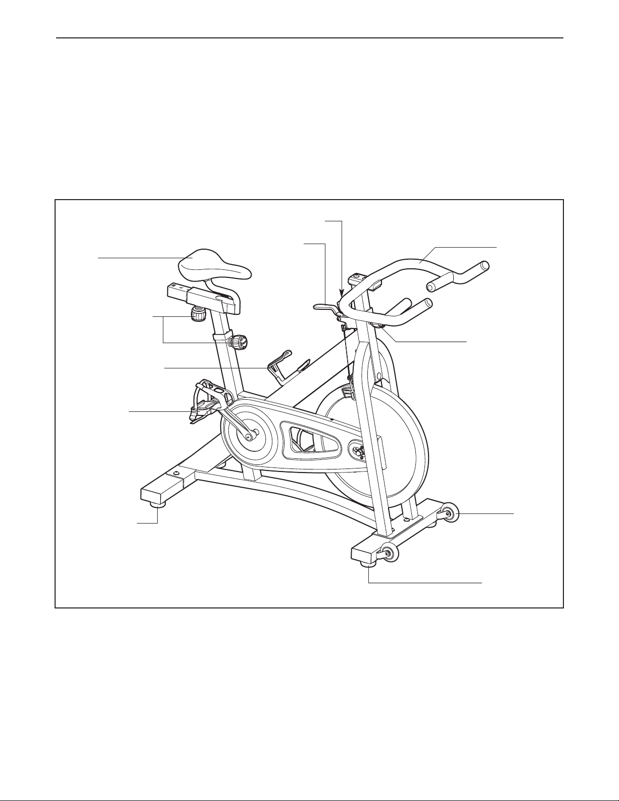
BEFORE YOU BEGIN
Thank you for selecting the new PROFORM®290 SPX
exercise bike. Cycling is an effective exercise for
increasing cardiovascular fitness, building endurance,
and toning the body. The 290 SPX exercise bike provides a selection of features designed to make your
workouts at home more effective and enjoyable.
For your benefit, read this manual carefully before
you use the exercise bike. If you have questions
Resistance Knob
Brake Lever
Seat
Adjustment Knob
Water Bottle Holder
after reading this manual, please see the front cover
of this manual. To help us assist you, note the product
model number and serial number before contacting
us. The model number and the location of the serial
number decal are shown on the front cover of this
manual.
Before reading further, please familiarize yourself with
the parts that are labeled in the drawing below.
Handlebar
Adjustment Knob
Pedal/Strap
Leveling Foot
Wheel
Leveling Foot
4
Page 5

ASSEMBLY
Assembly requires two persons. Place all parts of the exercise bike in a cleared area and remove the packing
materials. Do not dispose of the packing materials until assembly is completed.
In addition to the included tool(s), assembly requires an adjustable wrench and a Phillips
screwdriver .
Note: If a part is not in the hardware kit, check to see if it has been preattached.
1. Identify the Rear Stabilizer (7), which does not
have wheels.
Attach the Rear Stabilizer (7) to the Frame (1)
with two M10 x 25mm Screws (34) and two
M10 Washers (33).
1
34
33
1
7
2. Orient the Front Stabilizer (8) so that the
Wheels (21) are in the position shown.
Attach the Front Stabilizer (8) to the Frame (1)
with two M10 x 25mm Screws (34) and two
M10 Washers (33).
2
34
33
34
33
1
21
8
21
5
Page 6

3. Identify the Right Pedal (35), which is marked
with an “R.”
Using an adjustable wrench, firmly tighten the
Right Pedal (35) clockwise into the Right
Crank Arm (31).
3
Tighten the Left Pedal (61) counterclockwise
into the Left Crank Arm (not shown).
4. Orient the Handlebar Post (4) as shown.
Locate the Adjustment Knob (23) on the front of
the Frame (1). Loosen the Adjustment Knob
and pull it outward. Then, insert the Handlebar
Post (4) into the Frame.
Move the Handlebar Post (4) upward or downward to the desired position, release the
Adjustment Knob (23) into an adjustment hole
in the Handlebar Post, and then tighten the
Adjustment Knob. Make sure that the
Adjustment Knob is firmly engaged in an
adjustment hole.
1
3
35
61
4
4
1
23
5. Attach the Handlebar (5) to the Handlebar Post
(4) with two M10 x 25mm Screws (34) and two
M10 Washers (33).
5
33
34
5
4
6
Page 7

6. Orient the Seat Post (2) as shown.
Locate the Adjustment Knob (23) on the rear of
he Frame (1). Loosen the Adjustment Knob
t
and pull it outward. Then, insert the Seat Post
2) into the Frame.
(
6
Move the Seat Post (2) upward or downward to
the desired position, release the Adjustment
Knob (23) into an adjustment hole in the Seat
Post, and then tighten the Adjustment Knob.
Make sure that the Adjustment Knob is
firmly engaged in an adjustment hole.
7. Orient the Seat (22) and the Seat Carriage (3)
as shown.
See the inset drawing. Attach the Seat (22) to
the Seat Carriage (3) with two M8 Hex Nuts
(27). Make sure that the nose of the Seat is
pointing straight ahead before you tighten
the Hex Nuts.
2
23
1
7
22
2
Locate the Adjustment Knob (23) on the Seat
Post (2). Loosen the Adjustment Knob and pull
it outward. Then, insert the Seat Carriage (3)
into the Seat Post.
Slide the Seat Carriage (3) to the desired position and then release the Adjustment Knob (23)
into one of the adjustment holes in the Seat
Carriage. Make sure that the Adjustment
Knob is firmly engaged in an adjustment
hole.
8. Make sure that all parts are properly tightened before you use the exercise bike. Note: After assembly
is completed, some extra parts may be left over. Place a mat beneath the exercise bike to protect the floor.
23
1
3
22
3
27
7
Page 8

HOW TO USE THE EXERCISE BIKE
HOW TO ADJUST THE ANGLE OF THE SEAT
You can adjust the angle of the seat to the position
hat is most comfortable. You can also slide your seat
t
forward or backward to increase your comfort or to
djust the distance to the handlebar.
a
To adjust the seat, see the inset drawing in assembly
step 7 on page 7. Loosen the nuts on the seat clamp
a few turns, and then tilt the seat upward or downward
or slide the seat forward or backward to the desired
position. Then, retighten the nuts.
HOW TO ADJUST THE HORIZONTAL POSITION OF
THE SEAT
To adjust the position
of the seat, first
loosen the adjustment knob and pull it
downward. Then,
move the seat forward or backward,
release the adjustment knob into an
adjustment hole in the seat carriage, and firmly tighten
the adjustment knob. Make sure that the adjustment
knob is engaged in an adjustment hole.
Seat
Adjustment
Knob
HOW TO ADJUST THE SEAT POST
For effective exercise, the seat should be at the
roper height. As you pedal, there should be a slight
p
bend in your knees when the pedals are in the lowest
osition.
p
To adjust the height
of the seat post, first
loosen the adjustment knob and pull it
outward. Then, move
the seat post upward
or downward, release
the adjustment knob
into an adjustment
hole in the seat post,
and firmly tighten the adjustment knob. Make sure
that the adjustment knob is engaged in an adjustment hole.
HOW TO ADJUST THE HANDLEBAR POST
To adjust the height
of the handlebar
post, first loosen the
adjustment knob and
pull it outward. Then,
move the handlebar
post upward or
downward, release
the adjustment knob
into an adjustment
hole in the handlebar post, and firmly tighten the
adjustment knob. Make sure that the adjustment
knob is engaged in an adjustment hole.
Seat
Post
Adjustment
Knob
Handlebar
Post
Adjustment
Knob
8
Page 9
HOW TO ADJUST THE PEDAL STRAPS
HOW TO LEVEL THE EXERCISE BIKE
To tighten the pedal straps (see the drawing on page
), simply pull the ends of the pedal straps. To loosen
4
the pedal straps, press and hold the tabs on the buck-
es, adjust the pedal straps to the desired position,
l
and then release the tabs.
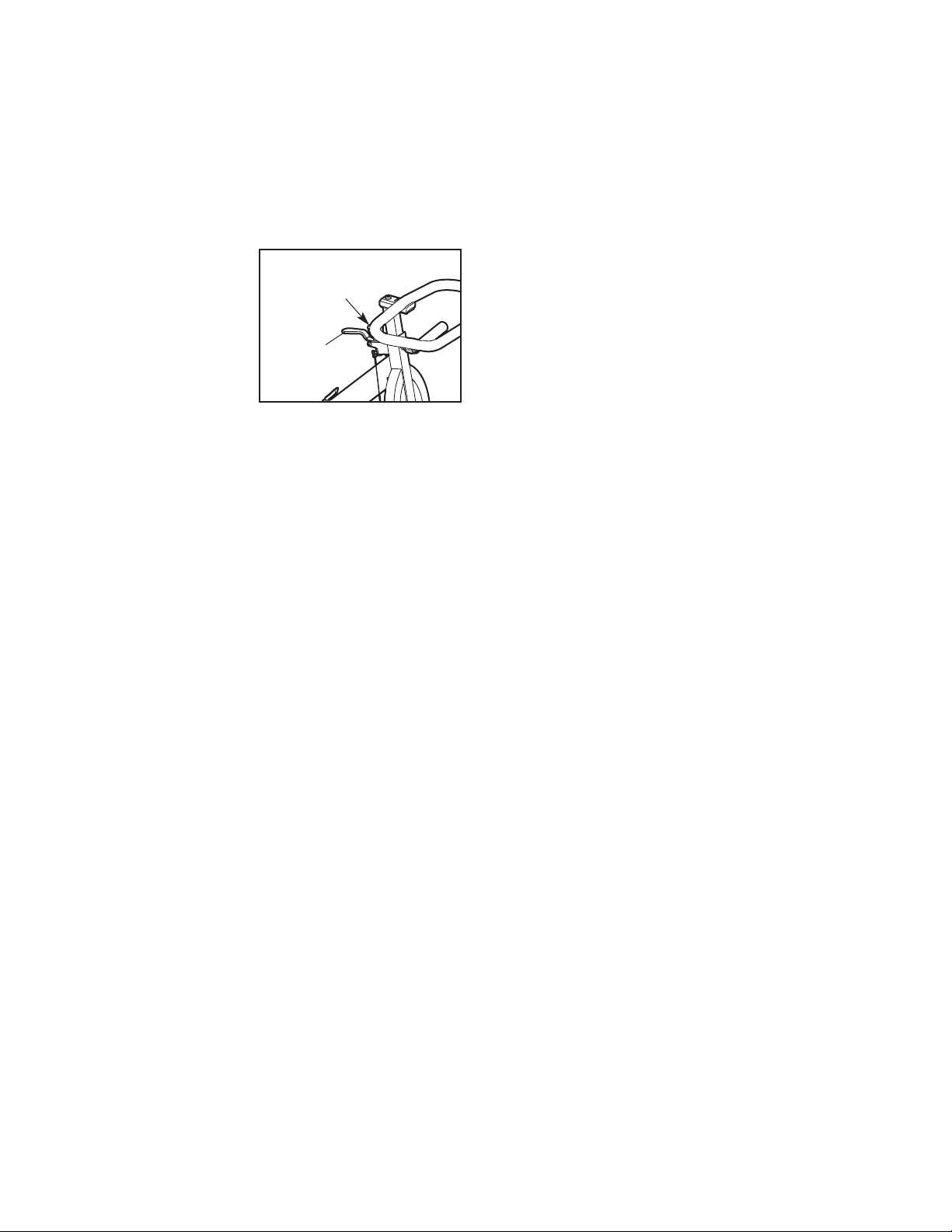
HOW TO ADJUST THE PEDALING RESISTANCE
To increase the
resistance of the
pedals, turn the
resistance knob
clockwise; to
decrease the resistance, turn the
resistance knob
counterclockwise.
To stop the flywheel, push the brake lever downward. The flywheel should quickly come to a
complete stop.
IMPORTANT: When the exercise bike is not in use,
tighten the resistance knob completely.
Resistance
Knob
Brake
Lever
If the exercise bike rocks slightly on your floor during
se, turn one or both of the leveling feet on the front
u
or rear stabilizer (see the drawing on page 4) until the
ocking motion is eliminated.
r
HOW TO MAINTAIN THE EXERCISE BIKE
Inspect and tighten all parts of the exercise bike regularly. Replace any worn parts immediately.
To clean the exercise bike, use a damp cloth and a
small amount of mild detergent. IMPORTANT: To
avoid damage to the console, keep liquids away
from the console and keep the console out of
direct sunlight.
9
Page 10

PART LIST M
Key No. Qty. Description Key No. Qty. Description
odel No. PFEX02909.2 R0811A
1
21Seat Post
31Seat Carriage
41Handlebar Post
51Handlebar
62M12 Hex Nut
71Rear Stabilizer
81Front Stabilizer
91Brake Lever
10 1 Felt Washer
11 1 Resistance Knob
12 1 Left Crank Arm
13 10 #8 x 13mm Screw
14 1 Right Shield
15 1 Left Shield
16 4 Leveling Foot
17 2 Seat Post Bushing
18 4 Stabilizer Cap
19 3 Post Cap
20 1 Shield Cover
21 2 Wheel
22 1 Seat
23 3 Adjustment Knob
24 1 Brake Cap
25 1 Frame Cap
26 2 11.5mm Plastic Spacer
27 2 M8 Hex Nut
28 1 Chain
29 2 Bracket Washer
30 1 Crank Axle
31 1 Right Crank Arm/Crank Wheel
32 2 Crank Cap
33 6 M10 Washer
34 6 M10 x 25mm Screw
1 Frame
5 1 Right Pedal/Strap
3
36 1 Flywheel
37 1 Flywheel Axle
38 2 Flywheel Bracket
39 1 Sleeve
40 2 M8 Locknut
41 2 Brake Pad
42 1 Brake Clamp
43 1 Small Knob Washer
44 2 Flywheel Bearing
45 2 Crank Bearing
46 2 M10 x 40mm Screw
47 1 Flywheel Sprocket
48 2 Snap Ring
49 4 M10 Hex Nut
50 1 8mm Bolt Set
51 1 M6 x 30mm Bolt
52 2 Brake Pad Mount
53 2 Crank Nut
54 2 #8 x 25mm Screw
55 3 M12 Thin Hex Nut
56 1 M6 Flange Nut
57 2 Spanner Nut
58 1 M10 Locknut
59 2 M5 x 12mm Screw
60 1 Water Bottle Holder
61 1 Left Pedal/Strap
62 1 Handlebar Post Bushing
63 2 Brake Cable
64 1 Caliper Brake
65 2 M5 Washer
66 2 M10 Nut
*–Assembly Tool
*–Userʼs Manual
Note: Specifications are subject to change without notice. For information about ordering replacement parts, see
the back cover of this manual. *These parts are not illustrated.
10
Page 11

EXPLODED DRAWING M
19
1
7
2
22
3
23
19
3
4
33
4
19
5
62
50
11
43
10
9
50
42
13
23
60
63
58
17
23
12
53
32
61
61
56
24
25
64
51
41
52
34
33
34
33
1
18
46
66
21
49
16
66
21
46
49
16
18
8
49
16
18
7
6
29
40
38
55
39
44
44
36
31
47
28
57
37
55
38
40
29
6
20
13
65
59
13
14
13
13
35
32
53
48
30
45
26
15
54
18
49
16
45
48
2
7
2
7
odel No. PFEX02909.2 R0811A
11
Page 12

ORDERING REPLACEMENT PARTS
To order replacement parts, please see the front cover of this manual. To help us assist you, be prepared to
provide the following information when contacting us:
• the model number and serial number of the product (see the front cover of this manual)
• the name of the product (see the front cover of this manual)
• the key number and description of the replacement part(s) (see the PART LIST and the EXPLODED
DRAWING near the end of this manual)
LIMITED WARRANTY
IMPORTANT: You must register this product within 30 days of the purchase date to avoid added
fees for service needed under warranty. Go to www.proformservice.com/registration.
ICON Health & Fitness, Inc. (ICON) warrants this product to be free from defects in workmanship and
material, under normal use and service conditions. The frame is warranted for five (5) years from the date
of purchase. Parts and labor are warranted for ninety (90) days from the date of purchase.
This warranty extends only to the original purchaser (customer). ICONʼs obligation under this warranty is
limited to repairing or replacing, at ICONʼs option, the product through one of its authorized service centers. All repairs for which warranty claims are made must be preauthorized by ICON. If the product is
shipped to a service center, freight charges to and from the service center will be the customerʼs responsibility. If replacement parts are shipped while the product is under warranty, the customer will be
responsible for a minimal handling charge. For in-home service, the customer will be responsible for a
minimal trip charge. This warranty does not extend to freight damage to the product. This warranty will
automatically be voided if the product is used as a store display model, if the product is purchased or
transported outside the USA, if all instructions in this manual are not followed, if the product is abused or
improperly or abnormally used, or if the product is used for commercial or rental purposes. No other warranty beyond that specifically set forth above is authorized by ICON.
ICON is not responsible or liable for indirect, special, or consequential damages arising out of or in connection with the use or performance of the product; damages with respect to any economic loss, loss of
property, loss of revenues or profits, loss of enjoyment or use, or costs of removal or installation; or other
consequential damages of any kind. Some states do not allow the exclusion or limitation of incidental or
consequential damages. Accordingly, the above limitation may not apply to the customer.
The warranty extended hereunder is in lieu of any and all other warranties, and any implied warranties of
merchantability or fitness for a particular purpose are limited in their scope and duration to the terms set
forth herein. Some states do not allow limitations on how long an implied warranty lasts. Accordingly, the
above limitation may not apply to the customer.
This warranty provides specific legal rights; the customer may have other rights that vary from state to state.
ICON Health & Fitness, Inc., 1500 S. 1000 W., Logan, UT 84321-9813
Part No. 317156 R0811A Printed in China © 2011 ICON IP, Inc.
 Loading...