

Page 1
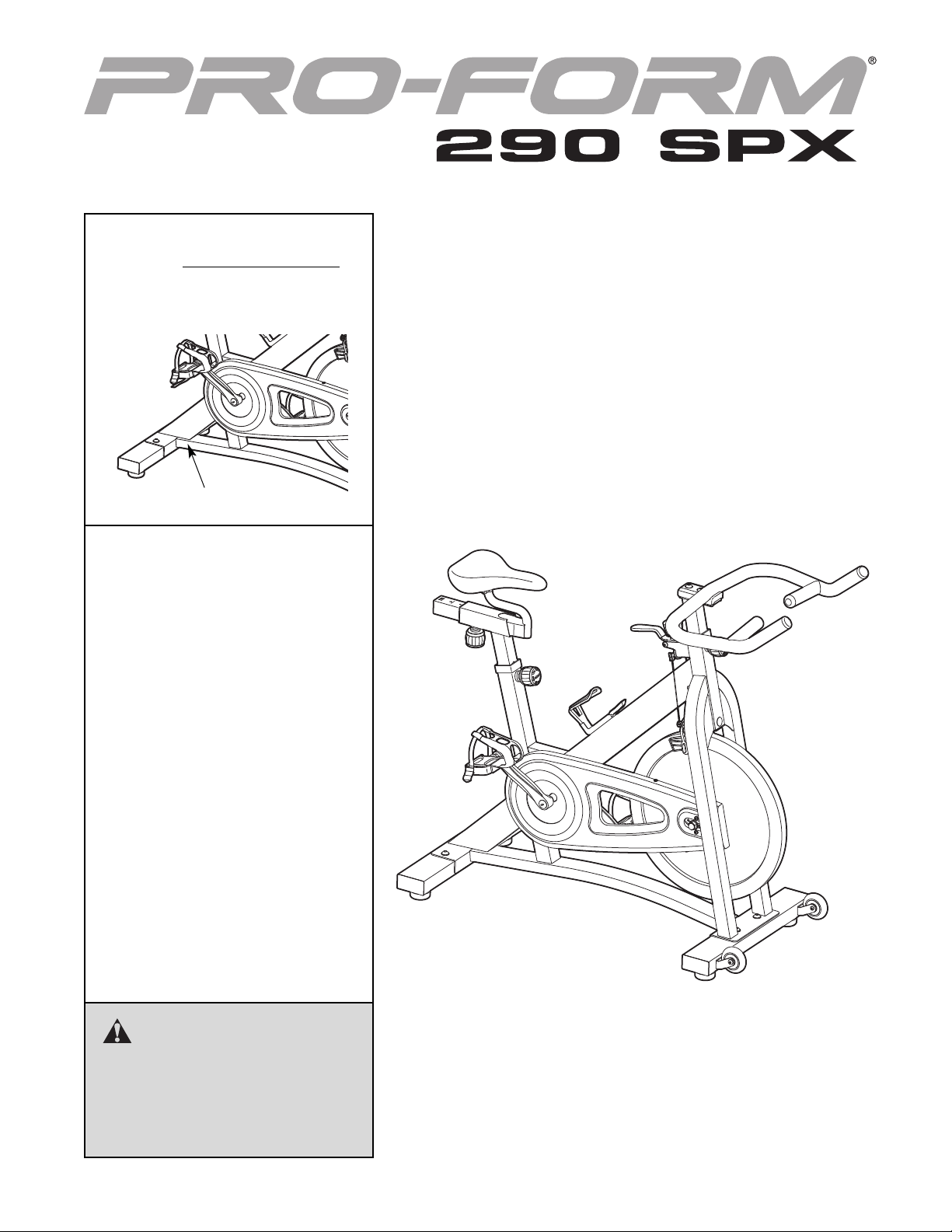
Model No. PFEVEX74910.0
Serial No.
Write the serial number in the
space above for reference.
Serial Number Decal
QUESTIONS?
If you have questions, or if there are
missing parts, please contact us:
Call: 08457 089 009
From Ireland: 053 92 36102
E-mail: Visit www.iconsupport.eu
Write:
ICON Health & Fitness, Ltd.
c/o HI Group PLC, Express Way
Whitwood, West Yorkshire
WF10 5QJ
UK
USERʼS MANUAL
CAUTION
Read all precautions and instructions in this manual before using
this equipment. Keep this manual
for future reference.
www.iconeurope.com
Page 2
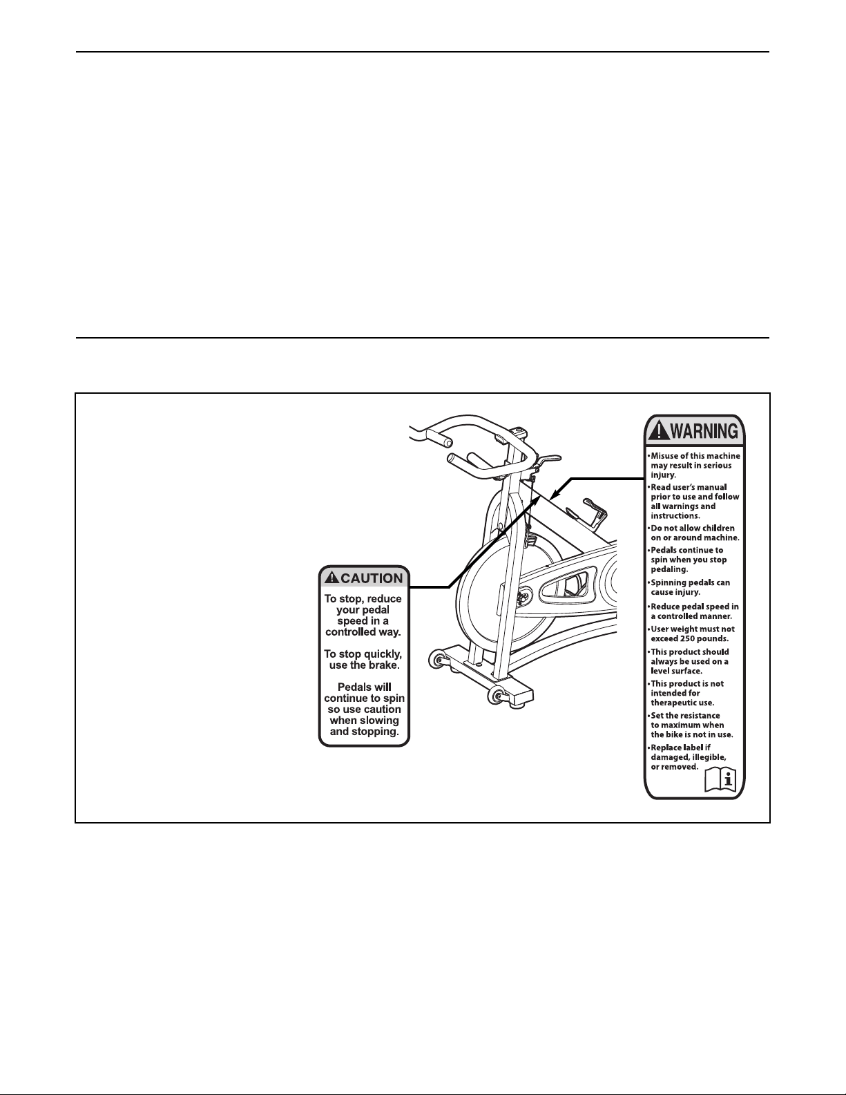
TABLE OF CONTENTS
WARNING DECAL PLACEMENT . . . . . . . . . . . . . . . . . . . . . . . . . . . . . . . . . . . . . . . . . . . . . . . . . . . . . . . . . . . . . .2
IMPORTANT PRECAUTIONS . . . . . . . . . . . . . . . . . . . . . . . . . . . . . . . . . . . . . . . . . . . . . . . . . . . . . . . . . . . . . . . .3
BEFORE YOU BEGIN . . . . . . . . . . . . . . . . . . . . . . . . . . . . . . . . . . . . . . . . . . . . . . . . . . . . . . . . . . . . . . . . . . . . . .4
SSEMBLY . . . . . . . . . . . . . . . . . . . . . . . . . . . . . . . . . . . . . . . . . . . . . . . . . . . . . . . . . . . . . . . . . . . . . . . . . . . . . . .5
A
HOW TO USE THE EXERCISE BIKE . . . . . . . . . . . . . . . . . . . . . . . . . . . . . . . . . . . . . . . . . . . . . . . . . . . . . . . . . .8
EXERCISE GUIDELINES . . . . . . . . . . . . . . . . . . . . . . . . . . . . . . . . . . . . . . . . . . . . . . . . . . . . . . . . . . . . . . . . . . . .9
PART LIST . . . . . . . . . . . . . . . . . . . . . . . . . . . . . . . . . . . . . . . . . . . . . . . . . . . . . . . . . . . . . . . . . . . . . . . . . . . . . .10
EXPLODED DRAWING . . . . . . . . . . . . . . . . . . . . . . . . . . . . . . . . . . . . . . . . . . . . . . . . . . . . . . . . . . . . . . . . . . . . .11
ORDERING REPLACEMENT PARTS . . . . . . . . . . . . . . . . . . . . . . . . . . . . . . . . . . . . . . . . . . . . . . . . . .Back Cover
WARNING DECAL PLACEMENT
This drawing shows the location(s) of the
warning decal(s). If a decal is missing or
illegible, see the front cover of this manual and request a free replacement
decal. Apply the decal in the location
shown. Note: The decal(s) may not be
shown at actual size.
PROFORM is a registered trademark of ICON IP, Inc.
2
Page 3

IMPORTANT PRECAUTIONS
WARNING: To reduce the risk of serious injury, read all important precautions and
instructions in this manual and all warnings on your exercise bike before using your exercise bike.
ICON assumes no responsibility for personal injury or property damage sustained by or through the
use of this product.
1. Before beginning any exercise program,
consult your physician. This is especially
important for persons over age 35 or persons with pre-existing health problems.
2. Use the exercise bike only as described in
this manual.
3. It is the responsibility of the owner to ensure
that all users of the exercise bike are adequately informed of all precautions.
4. The exercise bike is intended for home use
only. Do not use the exercise bike in a commercial, rental, or institutional setting.
5. Keep the exercise bike indoors, away from
moisture and dust. Place the exercise bike
on a level surface, with a mat beneath it to
protect the floor or carpet. Make sure that
there is at least 2 ft. (0.6 m) of clearance
around the exercise bike.
6. Inspect and properly tighten all parts regularly. Replace any worn parts immediately.
8. Wear appropriate clothes while exercising;
do not wear loose clothes that could become
caught on the exercise bike. Always wear
athletic shoes for foot protection.
9. The exercise bike should not be used by
persons weighing more than 250 lbs.
(113 kg).
10. Always keep your back straight while using
the exercise bike; do not arch your back.
11. The exercise bike does not have a freewheel;
the pedals will continue to move until the flywheel stops. Reduce your pedaling speed in
a controlled way.
12. To stop the flywheel quickly, press the brake
lever downward.
13. Over exercising may result in serious injury
or death. If you feel faint or if you experience
pain while exercising, stop immediately and
cool down.
7. Keep children under age 12 and pets away
from the exercise bike at all times.
3
Page 4
BEFORE YOU BEGIN
Thank you for selecting the new PROFORM®290 SPX
exercise bike. Cycling is an effective exercise for
increasing cardiovascular fitness, building endurance,
and toning the body. The 290 SPX exercise bike provides a selection of features designed to make your
workouts at home more effective and enjoyable.
For your benefit, read this manual carefully before
you use the exercise bike. If you have questions
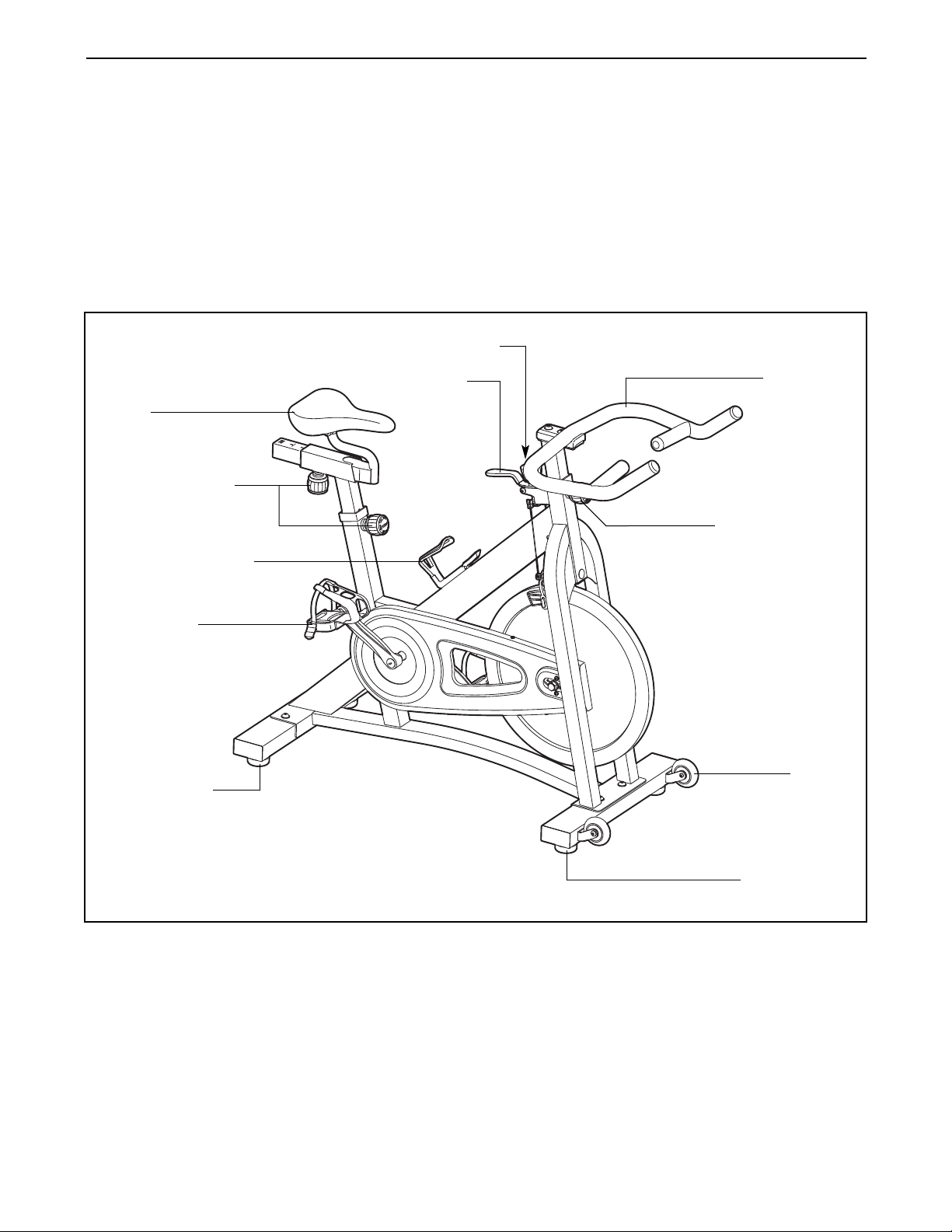
Resistance Knob
Brake Lever
Seat
Adjustment Knob
Water Bottle Holder
after reading this manual, please see the front cover
of this manual. To help us assist you, note the product
model number and serial number before contacting
us. The model number and the location of the serial
number decal are shown on the front cover of this
manual.
Before reading further, please familiarize yourself with
the parts that are labeled in the drawing below.
Handlebar
Adjustment Knob
Pedal/Strap
Leveling Foot
Wheel
Leveling Foot
4
Page 5

ASSEMBLY
Assembly requires two persons. Place all parts of the exercise bike in a cleared area and remove the packing
materials. Do not dispose of the packing materials until assembly is completed.
In addition to the included tool(s), assembly requires an adjustable wrench and a Phillips
screwdriver .
Note: If a part is not in the hardware kit, check to see if it has been preattached.
1. Remove the two screws, the two washers, and
the shipping bracket (not shown) from the rear
of the Frame (1). Discard the screws, washers,
and shipping bracket.
Identify the Rear Stabilizer (7), which does not
have wheels.
Tighten two M10 Hex Nuts (49) onto two
Leveling Feet (16). Next, tighten the Leveling
Feet into the underside of the Rear Stabilizer
(7).
Attach the Rear Stabilizer (7) to the Frame (1)
with two M10 x 25mm Screws (34) and two
M10 Washers (33).
2. Remove the two screws, the two washers, and
the shipping bracket (not shown) from the front
of the Frame (1). Discard the screws, washers,
and shipping bracket.
1
34
33
33
1
7
49
16
49
16
2
Orient the Front Stabilizer (8) so that the
Wheels (21) are in the position shown.
Attach the Front Stabilizer (8) to the Frame (1)
with two M10 x 25mm Screws (34) and two
M10 Washers (33).
34
33
1
8
21
21
5
Page 6

3. Identify the Right Pedal (35), which is marked
with an “R.”
sing an adjustable wrench, firmly tighten the
U
Right Pedal (35) clockwise into the Right Crank
rm (31).
A
Next, tighten the Left Pedal (61) counterclock-
wise into the Left Crank Arm (not shown).
3
1
3
61
IMPORTANT: Tighten both Pedals (35, 61) as
firmly as possible. After using the exercise
bike for one week, retighten the Pedals.
4. Orient the Handlebar Post (4) as shown.
Locate the Adjustment Knob (23) on the front of
the Frame (1). Loosen the Adjustment Knob
and pull it outward. Then, insert the Handlebar
Post (4) into the Frame.
Move the Handlebar Post (4) upward or downward to the desired position, release the
Adjustment Knob (23) into an adjustment hole
in the Handlebar Post, and then tighten the
Adjustment Knob.
Move the Handlebar Post (4) upward or
downward slightly to make sure that the
Adjustment Knob (23) is firmly engaged in
an adjustment hole in the Handlebar Post.
35
4
4
1
23
5. Attach the Handlebar (5) to the Handlebar Post
(4) with two M10 x 25mm Screws (34) and two
M10 Washers (33).
5
34
5
33
4
6
Page 7

6. Orient the Seat Post (2) as shown.
Locate the Adjustment Knob (23) on the rear of
he Frame (1). Loosen the Adjustment Knob
t
and pull it outward. Then, insert the Seat Post
2) into the Frame.
(
Move the Seat Post (2) upward or downward to
the desired position, release the Adjustment
Knob (23) into an adjustment hole in the Seat
Post, and then tighten the Adjustment Knob.
Move the Seat Post (2) upward or downward
slightly to make sure that the Adjustment
Knob (23) is firmly engaged in an adjustment hole in the Seat Post.
6
2
23
1
7. Orient the Seat (22) and the Seat Carriage (3)
as shown.
See the inset drawing. Attach the Seat (22) to
the Seat Carriage (3) with two M8 Hex Nuts
(66). Make sure that the nose of the Seat is
pointing straight ahead before you tighten
the Hex Nuts.
Locate the Adjustment Knob (23) on the Seat
Post (2). Loosen the Adjustment Knob and pull
it downward. Then, insert the Seat Carriage (3)
into the Seat Post.
Slide the Seat Carriage (3) to the desired position, release the Adjustment Knob (23) into one
of the adjustment holes in the Seat Carriage,
and then tighten the Adjustment Knob.
Make sure that the Adjustment Knob (23) is
firmly engaged in an adjustment hole in the
Seat Carriage (3).
7
22
2
3
23
1
22
3
66
8. Make sure that all parts are properly tightened before you use the exercise bike. Note: After assembly
is completed, some extra parts may be left over. Place a mat beneath the exercise bike to protect the floor.
7
Page 8

HOW TO USE THE EXERCISE BIKE
Inspect and tighten all parts of the exercise bike regularly. Replace any worn parts immediately.
o clean the exercise bike, use a damp cloth and a
T
small amount of mild detergent. IMPORTANT: To
void damage to the console, keep liquids away
a
from the console and keep the console out of
direct sunlight.
HOW TO ADJUST THE SEAT
To adjust the position of the seat, first
loosen the adjustment knob and pull it
downward. Then,
move the seat forward or backward,
release the adjustment knob into an
adjustment hole in
the seat carriage, and firmly tighten the adjustment
knob. Make sure that the adjustment knob is
engaged in an adjustment hole.
HOW TO ADJUST THE SEAT POST
For effective exercise, the seat should be at the
proper height. As you pedal, there should be a slight
bend in your knees when the pedals are in the lowest
position.
To adjust the height
of the seat post, first
loosen the adjustment knob and pull it
outward. Then, move
the seat post upward
or downward,
release the adjustment knob into an
adjustment hole in
the seat post, and firmly tighten the adjustment knob.
Make sure that the adjustment knob is engaged in
an adjustment hole.
Seat
Adjustment
Knob
Seat
Post
Adjustment
Knob
HOW TO ADJUST THE HANDLEBAR POST
To adjust the height
f the handlebar
o
post, first loosen the
djustment knob and
a
pull it outward. Then,
move the handlebar
post upward or
downward, release
the adjustment knob
into an adjustment
hole in the handlebar post, and firmly tighten the
adjustment knob. Make sure that the adjustment
knob is engaged in an adjustment hole.
HOW TO ADJUST THE PEDAL STRAPS
To tighten the pedal straps (see the drawing on page
4), simply pull the ends of the pedal straps. To loosen
the pedal straps, press and hold the tabs on the buckles, adjust the pedal straps to the desired position,
and then release the tabs.
HOW TO ADJUST THE PEDALING RESISTANCE
To increase the resistance of the pedals,
turn the resistance
knob clockwise; to
decrease the resistance, turn the
resistance knob
counterclockwise. To
stop the flywheel,
push the brake
lever downward. The flywheel should quickly
come to a complete stop.
HOW TO LEVEL THE EXERCISE BIKE
If the exercise bike rocks slightly on your floor during
use, turn one or both of the leveling feet on the front
or rear stabilizer (see the drawing on page 4) until the
rocking motion is eliminated.
Resistance
Brake
Lever
Handlebar
Post
Adjustment
Knob
Knob
8
Page 9

EXERCISE GUIDELINES
WARNING: B
or any exercise program, consult your physician. This is especially important for persons
over age 35 or persons with pre-existing
health problems.
The pulse sensor is not a medical device.
Various factors may affect the accuracy of
heart rate readings. The pulse sensor is
intended only as an exercise aid in determining heart rate trends in general.
These guidelines will help you to plan your exercise
program. For detailed exercise information, obtain a
reputable book or consult your physician. Remember,
proper nutrition and adequate rest are essential for
successful results.
efore beginning this
Burning Fat—To burn fat effectively, you must exer-
cise at a low intensity level for a sustained period of
time. During the first few minutes of exercise, your
body uses carbohydrate calories for energy. Only after
the first few minutes of exercise does your body begin
to use stored fat calories for energy. If your goal is to
burn fat, adjust the intensity of your exercise until your
heart rate is near the lowest number in your training
zone. For maximum fat burning, exercise with your
heart rate near the middle number in your training
zone.
Aerobic Exercise—If your goal is to strengthen your
cardiovascular system, you must perform aerobic
exercise, which is activity that requires large amounts
of oxygen for prolonged periods of time. For aerobic
exercise, adjust the intensity of your exercise until
your heart rate is near the highest number in your
training zone.
EXERCISE INTENSITY
Whether your goal is to burn fat or to strengthen your
cardiovascular system, exercising at the proper intensity is the key to achieving results. You can use your
heart rate as a guide to find the proper intensity level.
The chart below shows recommended heart rates for
fat burning and aerobic exercise.
To find the proper intensity level, find your age at the
bottom of the chart (ages are rounded off to the nearest ten years). The three numbers listed above your
age define your “training zone.” The lowest number is
the heart rate for fat burning, the middle number is the
heart rate for maximum fat burning, and the highest
number is the heart rate for aerobic exercise.
WORKOUT GUIDELINES
Warming Up—Start with 5 to 10 minutes of stretching
and light exercise. A warm-up increases your body
temperature, heart rate, and circulation in preparation
for exercise.
Training Zone Exercise—Exercise for 20 to 30 minutes with your heart rate in your training zone. (During
the first few weeks of your exercise program, do not
keep your heart rate in your training zone for longer
than 20 minutes.) Breathe regularly and deeply as you
exercise–never hold your breath.
Cooling Down—Finish with 5 to 10 minutes of
stretching. Stretching increases the flexibility of your
muscles and helps to prevent post-exercise problems.
EXERCISE FREQUENCY
To maintain or improve your condition, complete three
workouts each week, with at least one day of rest
between workouts. After a few months of regular exercise, you may complete up to five workouts each
week, if desired. Remember, the key to success is to
make exercise a regular and enjoyable part of your
everyday life.
9
Page 10

PART LIST—Model No. PFEVEX74910.0 R
Key No. Qty. Description Key No. Qty. Description
0510A
1
21Seat Post
31Seat Carriage
41Handlebar Post
51Handlebar
62M12 Acorn Nut
71Rear Stabilizer
81Front Stabilizer
91Brake Lever
10 1 Felt Washer
11 1 Resistance Knob
12 1 Left Crank Arm
13 7 Self-tapping Screw
14 1 Right Shield
15 1 Left Shield
16 4 Leveling Foot
17 2 Seat Post Bushing
18 4 Stabilizer Cap
19 3 Post Cap
20 1 Shield Cover
21 2 Wheel
22 1 Seat
23 3 Adjustment Knob
24 1 Brake Cap
25 1 Frame Cap
26 2 6.5mm Plastic Spacer
27 5 T1 Nut
28 1 Chain
29 2 Bracket Washer
30 1 Crank Axle
31 1 Right Crank Arm/Crank Wheel
32 2 Crank Cap
33 6 M10 Washer
34 6 M10 x 25mm Screw
35 1 Right Pedal/Strap
1 Frame
6 1 Flywheel
3
37 1 Flywheel Axle
38 2 Flywheel Bracket
39 1 Sleeve
40 2 M8 Locknut
41 2 Brake Pad
42 1 Brake Clamp
43 1 Small Knob Washer
44 2 Flywheel Bearing
45 2 Crank Bearing
46 4 Wheel Bearing
47 1 Flywheel Sprocket
48 2 Snap Ring
49 4 M10 Hex Nut
50 3 Wheel Bolt Set
51 1 M6 x 40mm Bolt
52 4 M5 Washer
53 2 Crank Nut
54 2 M5 x 25mm Screw
55 3 M12 Thin Hex Nut
56 1 M6 Flange Nut
57 2 Spanner Nut
58 1 M10 Locknut
59 2 M5 x 12mm Screw
60 1 Water Bottle Holder
61 1 Left Pedal/Strap
62 2 M5 x 12mm Screw
63 2 Brake Cable
64 1 Caliper Brake
65 2 Brake Pad Mount
66 2 M8 Hex Nut
67 1 Handlebar Post Bushing
*–Assembly Tool
*–Userʼs Manual
Note: Specifications are subject to change without notice. For information about ordering replacement parts, see
the back cover of this manual. *These parts are not illustrated.
10
Page 11

EXPLODED DRAWING—Model No. PFEVEX74910.0 R
19
1
7
2
22
3
2
3
19
34
3
3
33
4
19
5
67
50
11
43
10
9
50
42
62
23
60
52
63
58
17
23
12
53
32
61
61
56
24
25
64
51
41
65
34
33
34
33
1
18
50
50
46
21
46
49
16
46
50
21
46
50
49
16
18
8
49
16
18
7
6
29
40
38
55
39
44
44
36
31
47
28
57
37
55
38
40
29
6
20
27
13
52
59
13
14
13
13
35
35
35
32
53
48
30
45
27
26
15
54
27
18
49
16
45
52
48
6
6
6
6
0510A
11
Page 12

ORDERING REPLACEMENT PARTS
o order replacement parts, please see the front cover of this manual. To help us assist you, be prepared to
T
provide the following information when contacting us:
• the model number and serial number of the product (see the front cover of this manual)
• the name of the product (see the front cover of this manual)
• the key number and description of the replacement part(s) (see the PART LIST and the EXPLODED
DRAWING near the end of this manual)
Part No. 295571 R0510A Printed in China © 2010 ICON IP, Inc.
 Loading...