

Page 1
proform.com
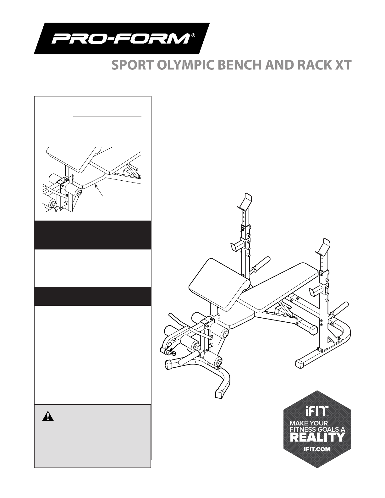
Model No. PFBE60120.0
Serial No.
Write the serial number in the space
above for reference.
Serial Number
Decal (under seat)
ACTIVATE YOUR
WARRANTY
To register your product and
activate your warranty today,
go to my.proform.com.
CUSTOMER CARE
USER’S MANUAL
For service at any time, go to
support.proform.com.
Or call 1-888-533-1333
Mon.–Fri. 6 a.m.–6 p.m. MT
Sat. 8 a.m.–12 p.m. MT
Please do not contact the store.
CAUTION
Read all precautions and
instructions in this manual before
using this equipment. Keep this
manual for future reference.
Page 2

TABLE OF CONTENTS
WARNING DECAL PLACEMENT . . . . . . . . . . . . . . . . . . . . . . . . . . . . . . . . . . . . . . . . . . . . . . . . . . . . . . . . . . . . . . .3
IMPORTANT PRECAUTIONS ..................................................................4
BEFORE YOU BEGIN. . . . . . . . . . . . . . . . . . . . . . . . . . . . . . . . . . . . . . . . . . . . . . . . . . . . . . . . . . . . . . . . . . . . . . . .6
PART IDENTIFICATION CHART. . . . . . . . . . . . . . . . . . . . . . . . . . . . . . . . . . . . . . . . . . . . . . . . . . . . . . . . . . . . . . . .8
ASSEMBLY . . . . . . . . . . . . . . . . . . . . . . . . . . . . . . . . . . . . . . . . . . . . . . . . . . . . . . . . . . . . . . . . . . . . . . . . . . . . . . . .9
ADJUSTMENT ............................................................................16
EXERCISE GUIDELINES ....................................................................19
PART LIST. . . . . . . . . . . . . . . . . . . . . . . . . . . . . . . . . . . . . . . . . . . . . . . . . . . . . . . . . . . . . . . . . . . . . . . . . . . . . . . .21
EXPLODED DRAWING. . . . . . . . . . . . . . . . . . . . . . . . . . . . . . . . . . . . . . . . . . . . . . . . . . . . . . . . . . . . . . . . . . . . . .22
ORDERING REPLACEMENT PARTS. . . . . . . . . . . . . . . . . . . . . . . . . . . . . . . . . . . . . . . . . . . . . . . . . . . Back Cover
LIMITED WARRANTY. . . . . . . . . . . . . . . . . . . . . . . . . . . . . . . . . . . . . . . . . . . . . . . . . . . . . . . . . . . . . . . Back Cover
PROFORM is a registered trademark of ICON Health & Fitness, Inc.
2
Page 3
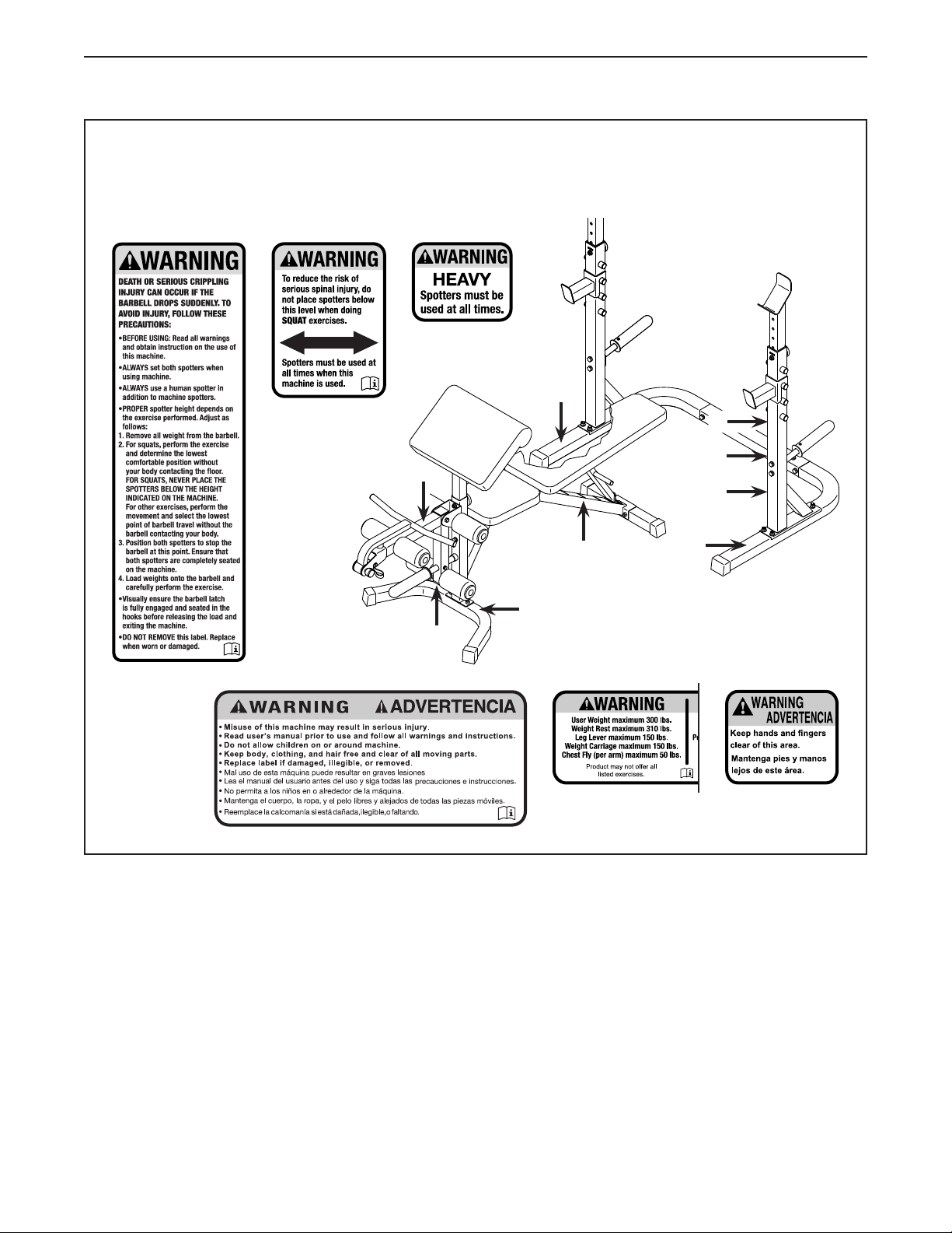
WARNING DECAL PLACEMENT
415226
415225
The decals shown here have been applied to the weight bench. If a decal is missing or illegible, call
the telephone number on the front cover of this manual and request a free replacement decal.
Apply the decal in the location shown. Note: The decals may not be shown at actual size.
1
2
4 5 6
3
5
6
6
5
4
2
3
1
4
3
Page 4

IMPORTANT PRECAUTIONS
WARNING: To reduce the risk of serious injury, read all important precautions and
instructions in this manual and all warnings on the weight bench before using the weight bench.
ICON assumes no responsibility for personal injury or property damage sustained by or through the
use of this product.
1. It is the responsibility of the owner to
ensure that all users of the weight bench are
adequately informed of all precautions.
2. Before beginning any exercise program,
consult your physician. This is especially
important for persons over the age of 35 or
persons with pre-existing health problems.
3. The weight bench is not intended for use
by persons with reduced physical, sensory,
or mental capabilities or lack of experience
and knowledge, unless they are given supervision or instruction about the use of the
weight bench by someone responsible for
their safety.
4. The weight bench is intended for home use
only. Do not use the weight bench in any
commercial, rental, or institutional setting.
5. Keep the weight
moisture and dust. Place the weight
on a level surface, with a mat beneath it to
protect the floor or carpet.
6. Make sure that there is enough clearance
around the weight
and use it.
7. Inspect and properly tighten all parts each
time the weight bench is used. Replace any
worn parts immediately.
bench
indoors, away from
bench
to mount, dismount,
bench
9. Wear appropriate clothes while exercising;
do not wear loose clothes that could become
caught on the weight bench. Always wear
athletic shoes for foot protection.
10. Keep hands and feet away from
moving parts.
11. Make sure that the adjustment knobs are fully
tightened before you use the weight bench.
12. Make sure that the curl bar pin is fully
engaged before you use the curl bar.
13. The weight bench is designed to support a
maximum user weight of 300 lbs. (136 kg)
and a maximum total weight of 610 lbs.
(277 kg). Do not use the weight bench with
more than 310 lbs. (141 kg) of weight. Do
not place more than 150 lbs. (68 kg) on the
leg lever. Do not place more than 310 lbs.
(141 kg) of weight, including a barbell, on the
weight rack. Note: The weight bench does
not include weight plates or a barbell.
14. Use the weight bench only as described in
this manual.
15. Over exercising may result in serious injury
or death. If you feel faint, if you become short
of breath, or if you experience pain while
exercising, stop immediately and cool down.
8. Keep children under age 16 and pets away
from the weight bench at all times.
4
Page 5
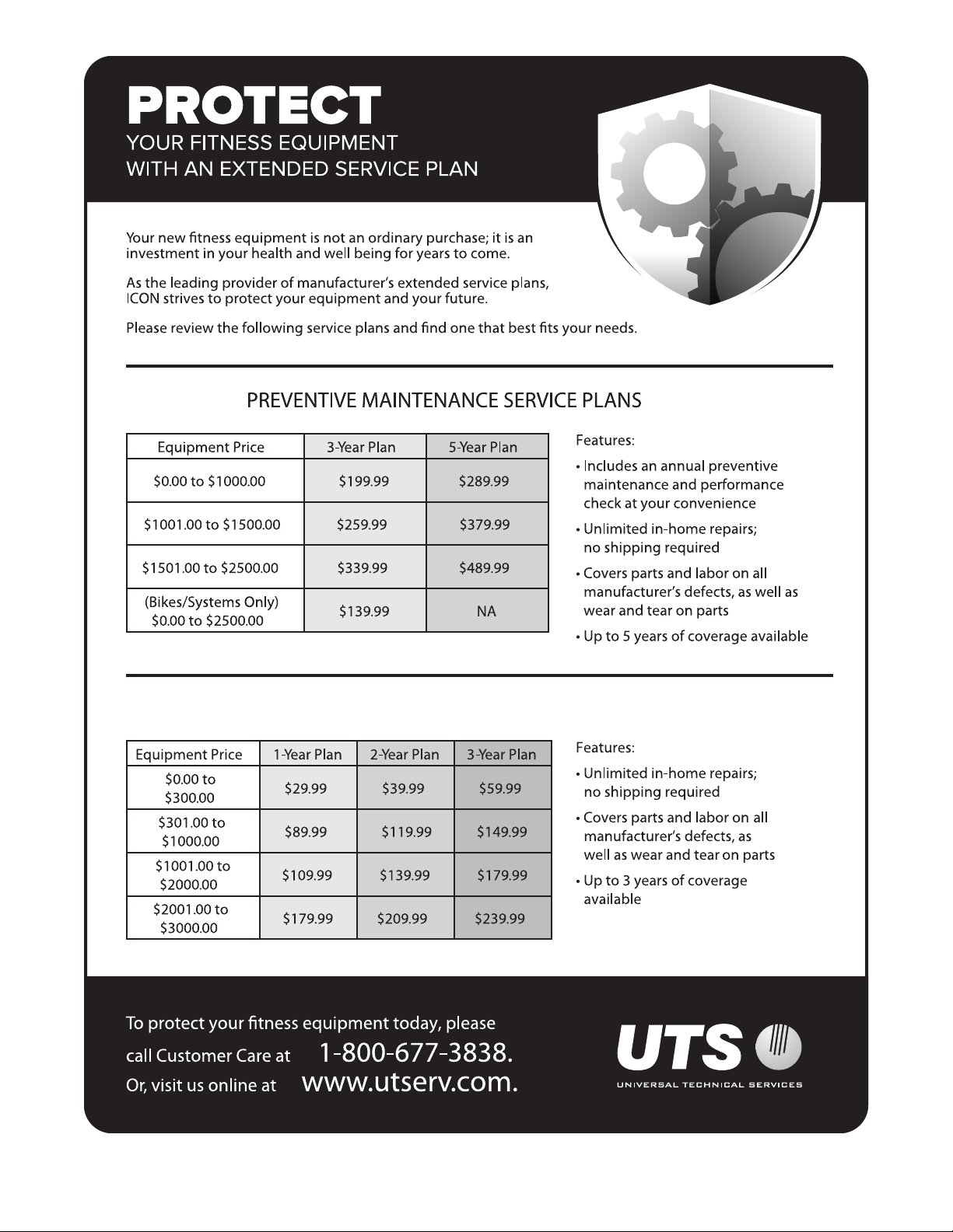
STANDARD SERVICE PLANS
5
Page 6
BEFORE YOU BEGIN
Thank you for selecting the versatile PROFORM®
SPORT OLYMPIC BENCH AND RACK XT weight
bench. The weight bench offers a selection of exercises designed to develop the major muscle groups of
the body. Whether your goal is to tone your body, build
dramatic muscle size and strength, or improve your
cardiovascular system, the weight bench will help you
to achieve the specific results you want.
For your benefit, read this manual carefully before
using the weight bench. If you have questions after
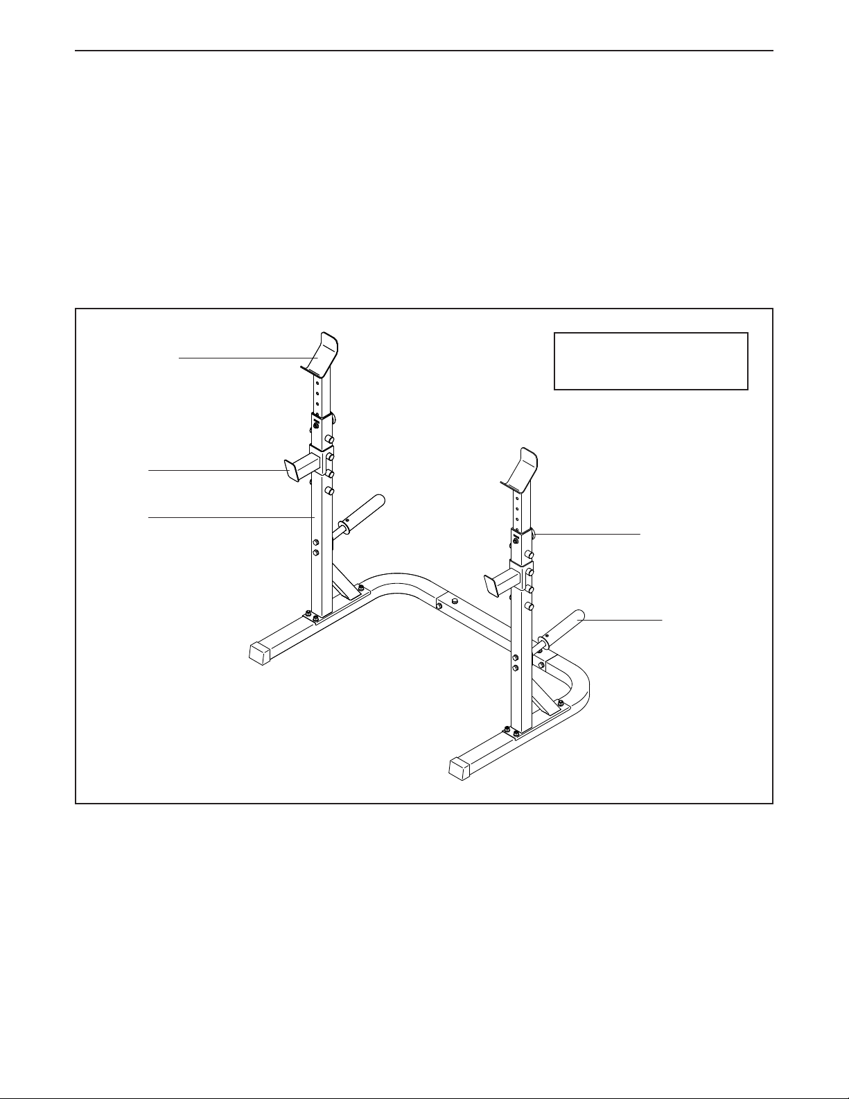
Weight Rest
Spotter
reading this manual, please see the front cover of this
manual. To help us assist you, note the product model
number and serial number before contacting us. The
model number and the location of the serial number
decal are shown on the front cover of this manual.
Before reading further, please review the drawing below
and familiarize yourself with the parts that are labeled.
Width: 4 ft. 1 in. (124 cm)
Length: 2 ft. 9 in. (83 cm)
Upright
Adjustment Knob
Storage Tube
6
Page 7
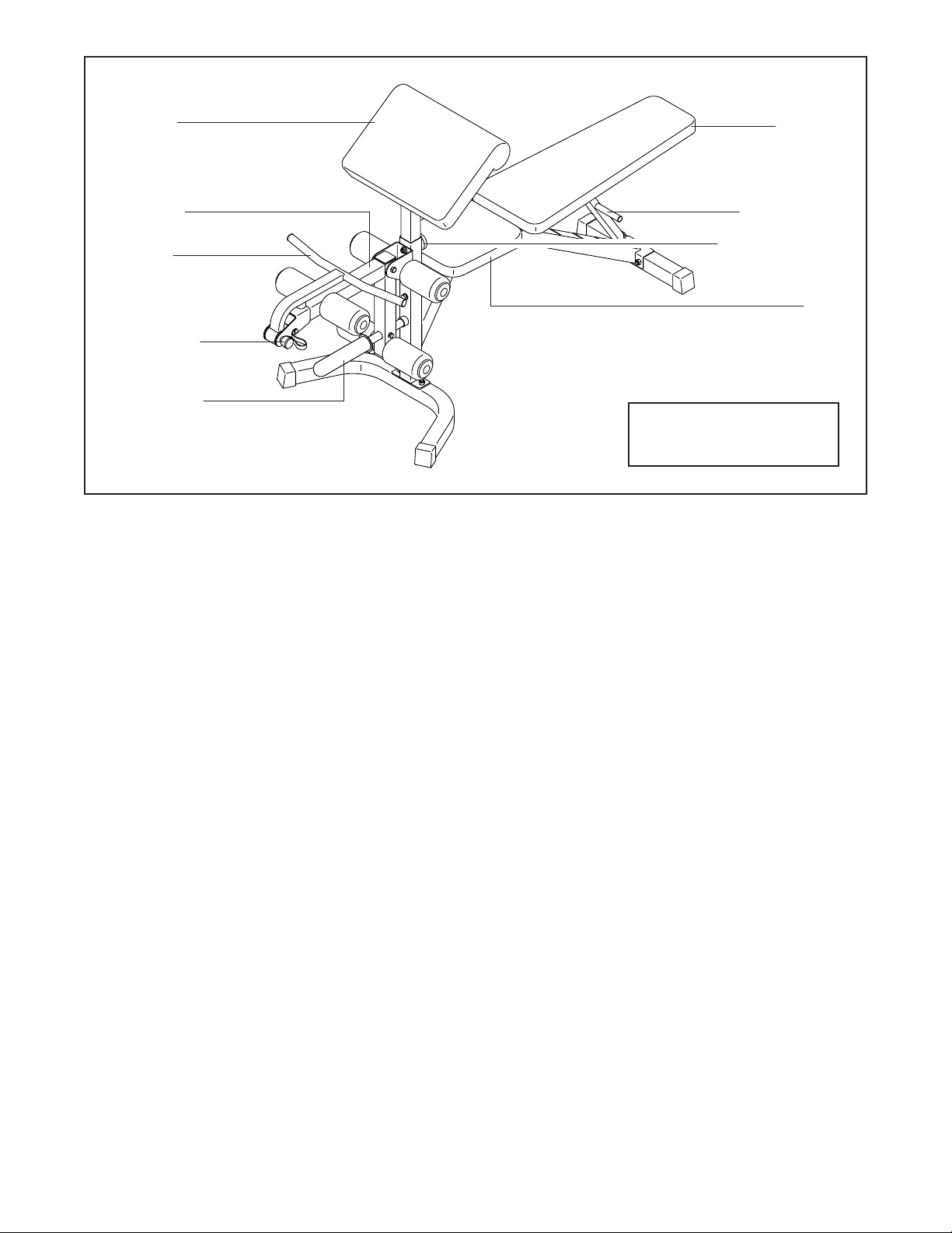
Curl Pad
Backrest
Leg Lever
Curl Bar
Curl Bar Pin
Weight Tube
Backrest Post
Adjustment Knob
Seat
Width: 2 ft. 3 in. (69 cm)
Length: 6 ft. (183 cm)
7
Page 8
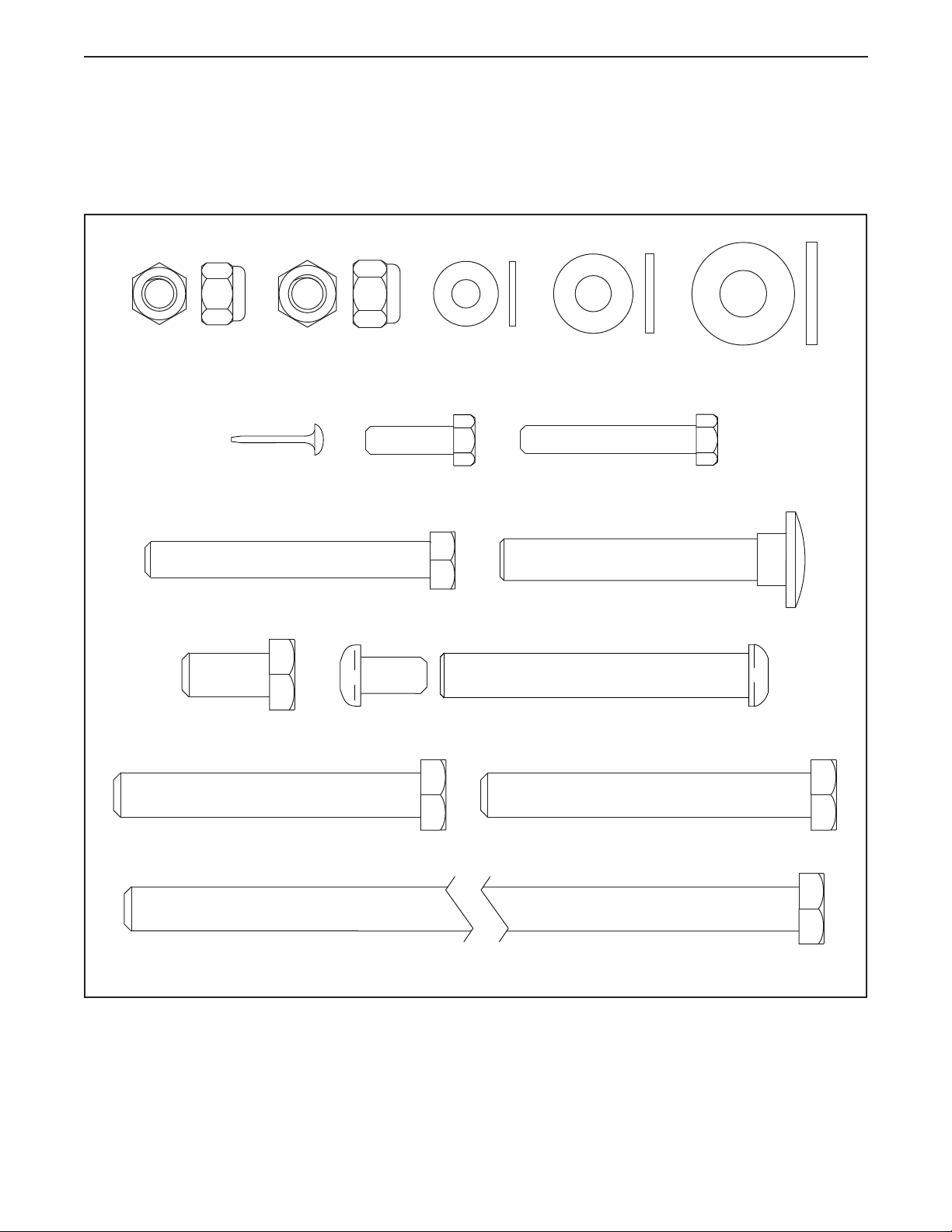
PART IDENTIFICATION CHART
Use the drawings below to identify the small parts needed for assembly. The number in parentheses below each
drawing is the key number of the part, from the PART LIST near the end of this manual. The number following
the key number is the quantity needed for assembly. Note: If a part is not in the hardware kit, check to see
whether it has been preassembled. Extra parts may be included.
M8 Locknut
(32)–1
M8 x 65mm Bolt (28)–1
M10 x 20mm
Screw (9)–6
M10 Locknut
M4 x 19mm
Screw (18)–3
(17)–17
M6 Washer
(59)–4
M6 x 20mm
Screw (33)–6
M8 Washer
(58)–2
M6 x 40mm Screw (56)–4
M10 x 65mm Carriage Bolt (16)–8
M10 x 70mm Bolt Set (60)–1
M10 Washer
(19)–18
M10 x 70mm Bolt (29)–4 M10 x 75mm Bolt (20)–4
M10 x 170mm Bolt (55)–2
8
Page 9
ASSEMBLY
• To hire an authorized service technician to
assemble the weight bench, call 1-800-445-2480.
• Because of its weight and size, assemble the
weight bench in the location where it will be used.
Make sure that there is enough clearance to walk
around it.
• Place all parts in a cleared area and remove the
packing materials. Do not dispose of the packing
materials until assembly is nished.
• Left parts are marked “L” or “Left” and right parts
are marked “R” or “Right.”
1. Go to my.proform.com on your computer and
register your product.
• documents your ownership
• activates your warranty
• Assembly requires two persons.
• For help identifying small parts, see page 8.
• In addition to the included tool(s), assembly
requires the following tool(s):
two adjustable wrenches
one Phillips screwdriver
one rubber mallet
Assembly may be easier if you have your own set
of wrenches. To avoid damaging parts, do not use
power tools.
1
• ensures priority customer support if assistance
is ever needed
Note: If you do not have internet access, call
Customer Care (see the front cover of this
manual) and register your product.
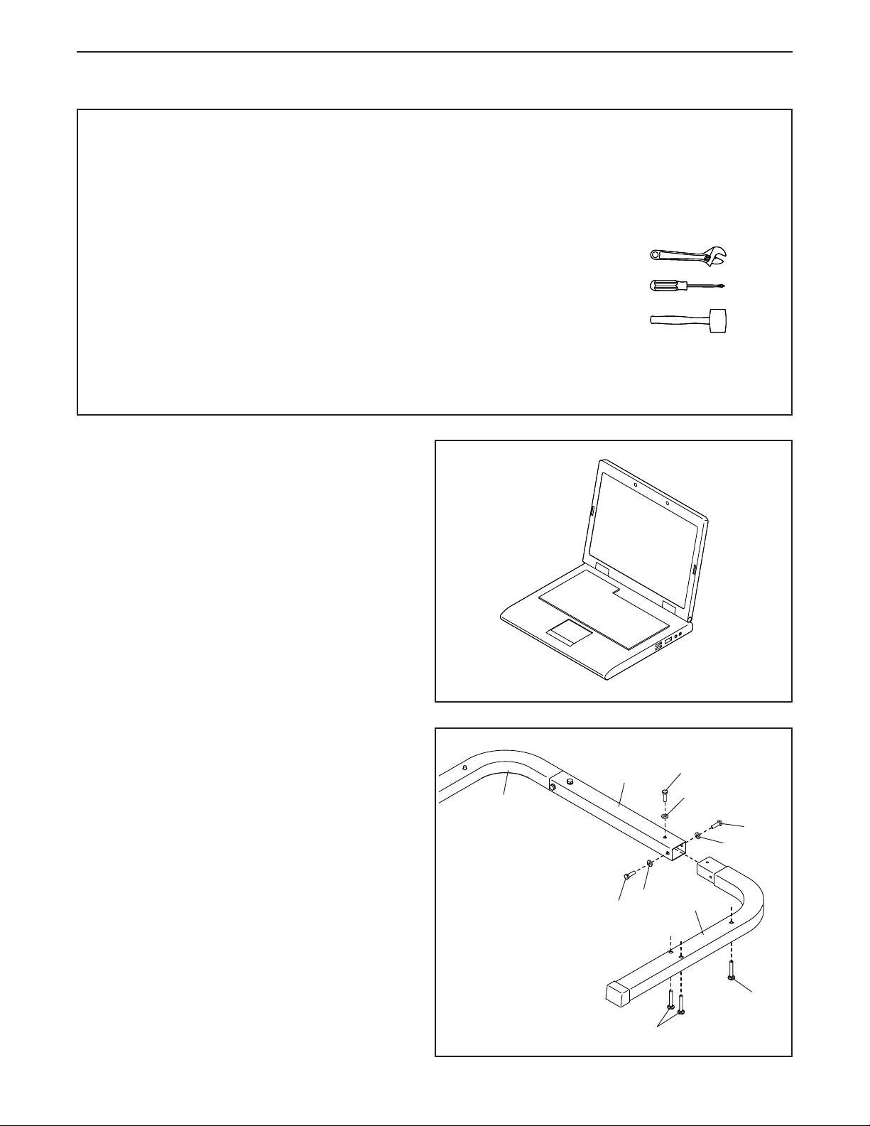
2. Insert three M10 x 65mm Carriage Bolts (16)
upward into the Left Base (2).
Next, insert the Left Base (2) into one end of
the Center Base (21). Attach the Left Base with
three M10 x 20mm Screws (9) and three M10
Washers (19); do not tighten the Screws yet.
Repeat this step for the Right Base (1).
2
21
1
19
9
9
19
9
19
2
16
16
9
Page 10
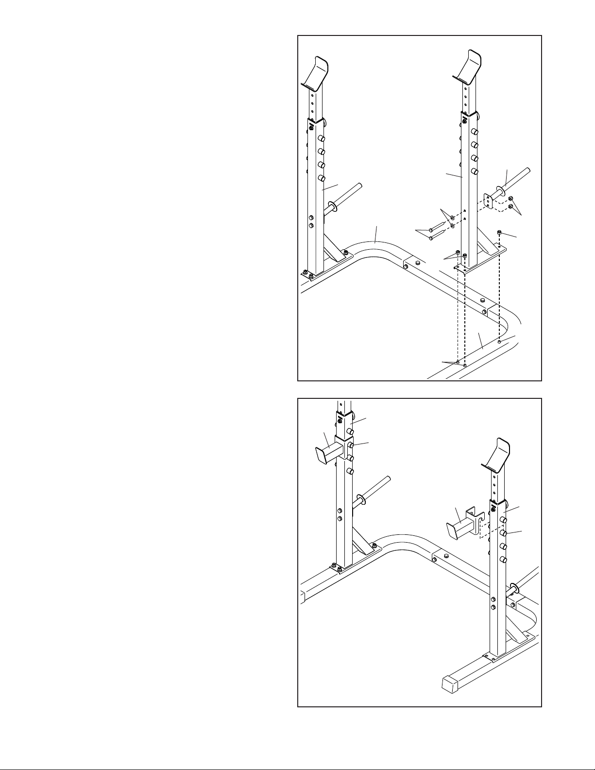
3. Orient one of the Uprights (3) as shown, and set
it over the three M10 x 65mm Carriage Bolts (16)
in the Left Base (2). Attach the Upright with three
M10 Locknuts (17).
Then, attach a Storage Tube (4) to the
Upright (3) with two M10 x 75mm Bolts (20),
two M10 Washers (19), and two M10 Locknuts
(17); insert both Bolts, and then tighten the
Locknuts.
3
Repeat this step for the other Upright (3) and
the Right Base (1).
See step 2. Tighten the six M10 x 20mm
Screws (9).
4. Set a Spotter (6) on a set of pegs (A) on the left
Upright (3).
Set the other Spotter (6) on a set of pegs (A)
on the right Upright (3). Make sure that both
Spotters are at the same height.
3
3
19
1
20
17
2
16
4
3
6
A
4
17
17
16
10
6
3
A
Page 11
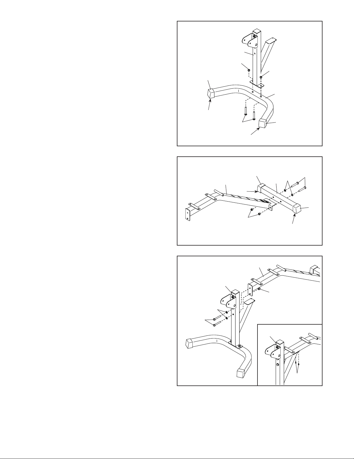
5. Orient the Front Stabilizer (23) so that the widest
sides (B) of the 50mm Square Outer Caps (46)
touch the floor.
5
Attach the Front Stabilizer (23) to the Front Leg
(25) with two M10 x 65mm Carriage Bolts (16)
and two M10 Locknuts (17); do not tighten the
Locknuts yet.
6. Orient the Rear Stabilizer (24) so that the widest
sides (B) of the 50mm Square Outer Caps (46)
touch the floor.
Attach the Rear Stabilizer (24) to the Frame
(22) with two M10 x 70mm Bolts (29), two M10
Washers (19), and two M10 Locknuts (17); do
not tighten the Locknuts yet.
25
17
17
46
23
B
24
46
19
29
46
16
B
6
46
22
B
7. Attach the Front Leg (25) to the Frame (22) with
two M10 x 70mm Bolts (29), two M10 Washers
(19), and an M10 Locknut (17); do not tighten
the Bolts or the Locknut yet.
See the inset drawing. Finish attaching the
Front Leg (25) with two M4 x 19mm Screws (18);
start both Screws, and then tighten them.
Then, tighten the two M10 x 70mm Bolts (29)
and the M10 Locknut (17).
See step 5–6. Tighten the M10 Locknuts (17).
17
B
7
25
19
29
22
17
25
18
11
Page 12
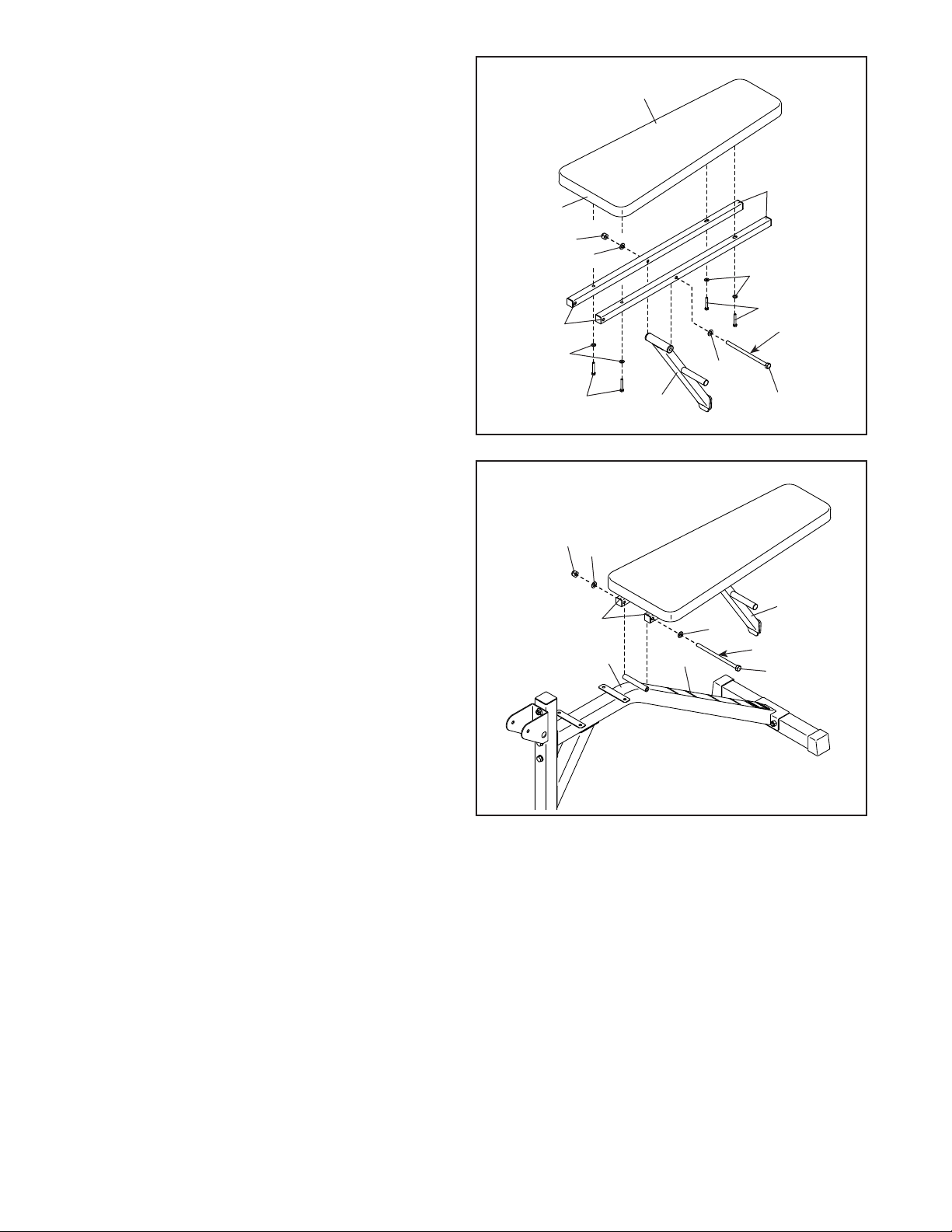
8. Using a plastic bag to keep your fingers clean,
apply some of the included grease to an
M10 x 170mm Bolt (55).
Next, orient the two Backrest Frames (37) so
that the indicated holes (C) are in the position
shown. Then, orient the Backrest Post (36) as
shown. Attach the Backrest Post to the Backrest
Frames with the M10 x 170mm Bolt (55), two
M10 Washers (19), and an M10 Locknut (17); do
not tighten the Locknut yet.
Then, orient the Backrest (40) so that the wide
end (D) is in the position shown, and attach it to
the Backrest Frames (37) with four M6 x 40mm
Screws (56) and four M6 Washers (59); do not
tighten the Screws yet.
8
40
37
D
17
19
C
59
59
56
Grease
19
9. Apply grease to an M10 x 170mm Bolt (55).
Attach the Backrest Frames (37) to the Frame
(22) with the M10 x 170mm Bolt (55), two M10
Washers (19), and an M10 Locknut (17). Do
not overtighten the Locknut; the Backrest
Frames must pivot easily.
Then, set the end of the Backrest Post (36) in
one of the slots (E) in the Frame (22).
See step 8. Tighten the M10 Locknut (17)
and the four M6 x 40mm Screws (56). Do not
overtighten the Locknut; the Backrest Post
(36) must pivot easily. To avoid damaging the
Backrest (40), tighten the Screws only until
the Backrest does not move or feel loose.
56
9
17
19
37
22
36
19
E
55
36
Grease
55
12
Page 13
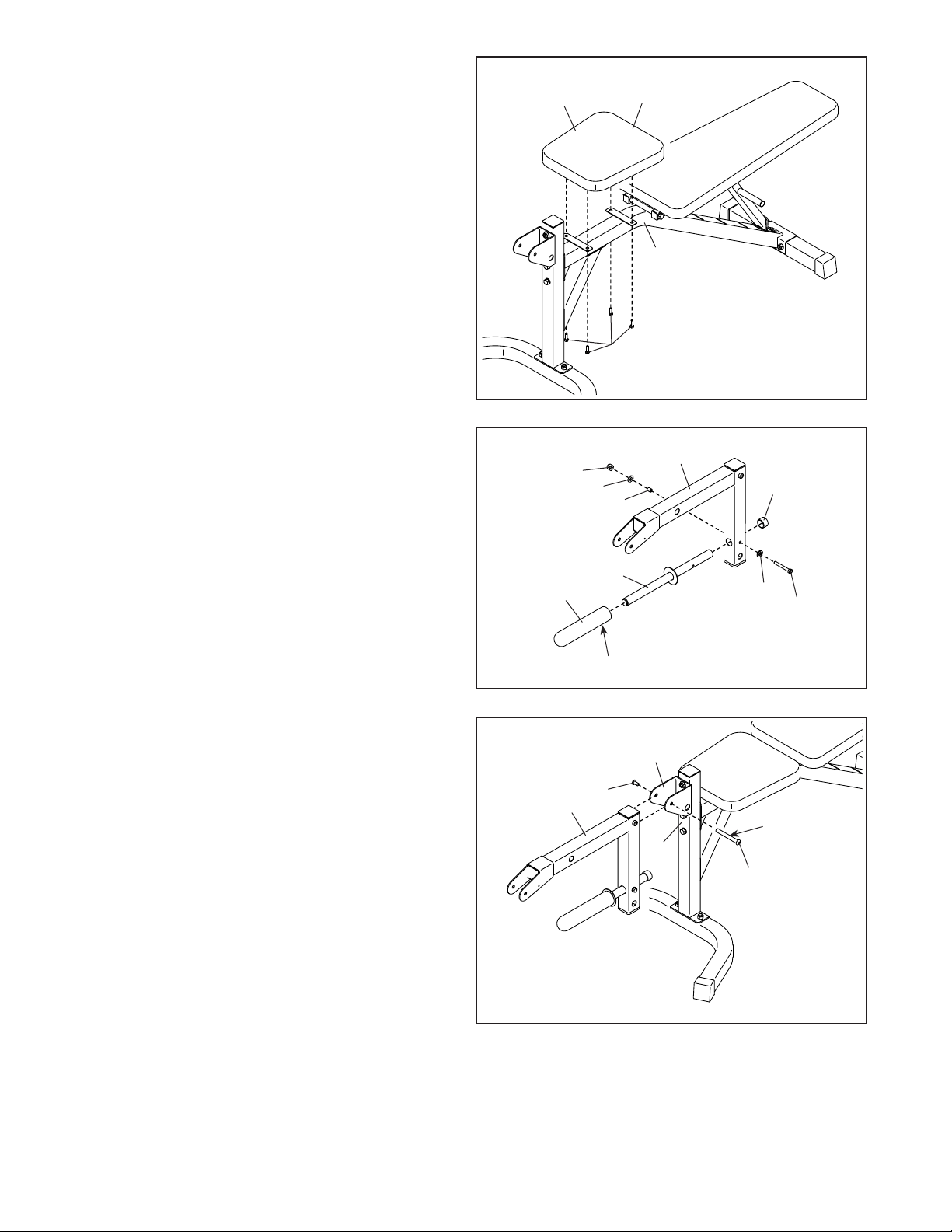
10. Orient the Seat (39) so that the wide end (F) is in
the position shown.
Attach the Seat (39) to the Frame (22) with four
M6 x 20mm Screws (33); start all four Screws,
and then tighten them. To avoid damaging
the Seat, tighten the Screws only until the
Seat does not move or feel loose.
10
39
F
22
33
11. Attach the Weight Tube (45) to the Leg Lever
(26) with an M8 x 65mm Bolt (28), two M8
Washers (58), a Spacer (35), and an M8
Locknut (32). Then, press the 25mm Round
Outer Cap (34) onto the Weight Tube.
If you plan to use Olympic weights (not included),
slide the Olympic Adapter (8) onto the Weight
Tube (45). Then, tighten the M8 x 10mm Set
Screw (10) in the Olympic Adapter.
12. Apply grease to the barrel of an M10 x 70mm
Bolt Set (60).
Attach the Leg Lever (26) to the Front Leg (25)
with the M10 x 70mm Bolt Set (60). Make sure
that the barrel of the Bolt Set is inserted
through both sides of the bracket (G) on the
Front Leg.
11
12
8
26
32
58
26
34
35
45
58
28
10
G
60
Grease
25
60
13
Page 14
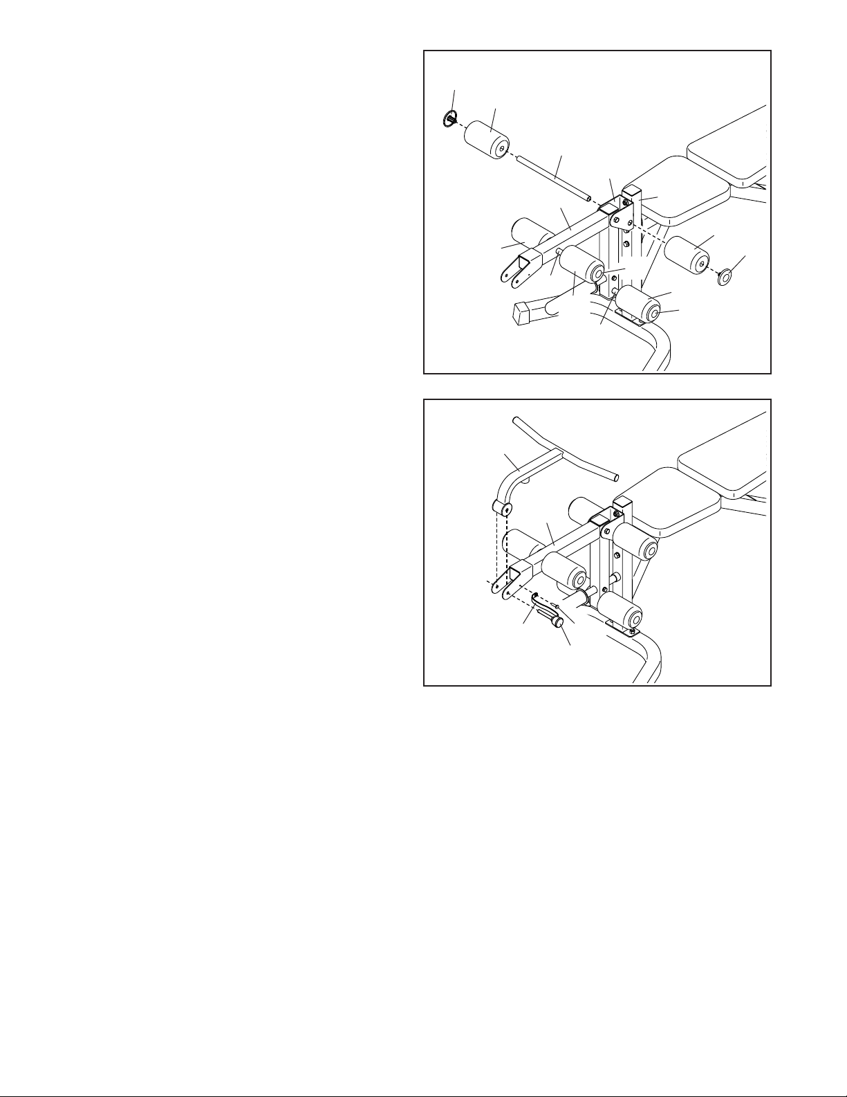
13. Insert the Long Pad Tube (57) into the bracket
(G) on the Front Leg (25). Then, slide two Foam
Pads (43) onto the Long Pad Tube, and press
two Pad Caps (44) into the Long Pad Tube.
13
44
43
Attach the two Short Pad Tubes (42) and the
remaining Foam Pads (43) and Pad Caps (44)
to the Leg Lever (26) in the same way.
14. Attach the Curl Bar (38) to the Leg Lever (26)
with the Curl Bar Pin (54).
Then, attach the tether (H) on the Curl Bar Pin
(54) to the Leg Lever (26) with an M4 x 19mm
Screw (18).
14
43
38
42
26
26
57
43
G
25
43
44
44
43
44
42
H
18
54
14
Page 15
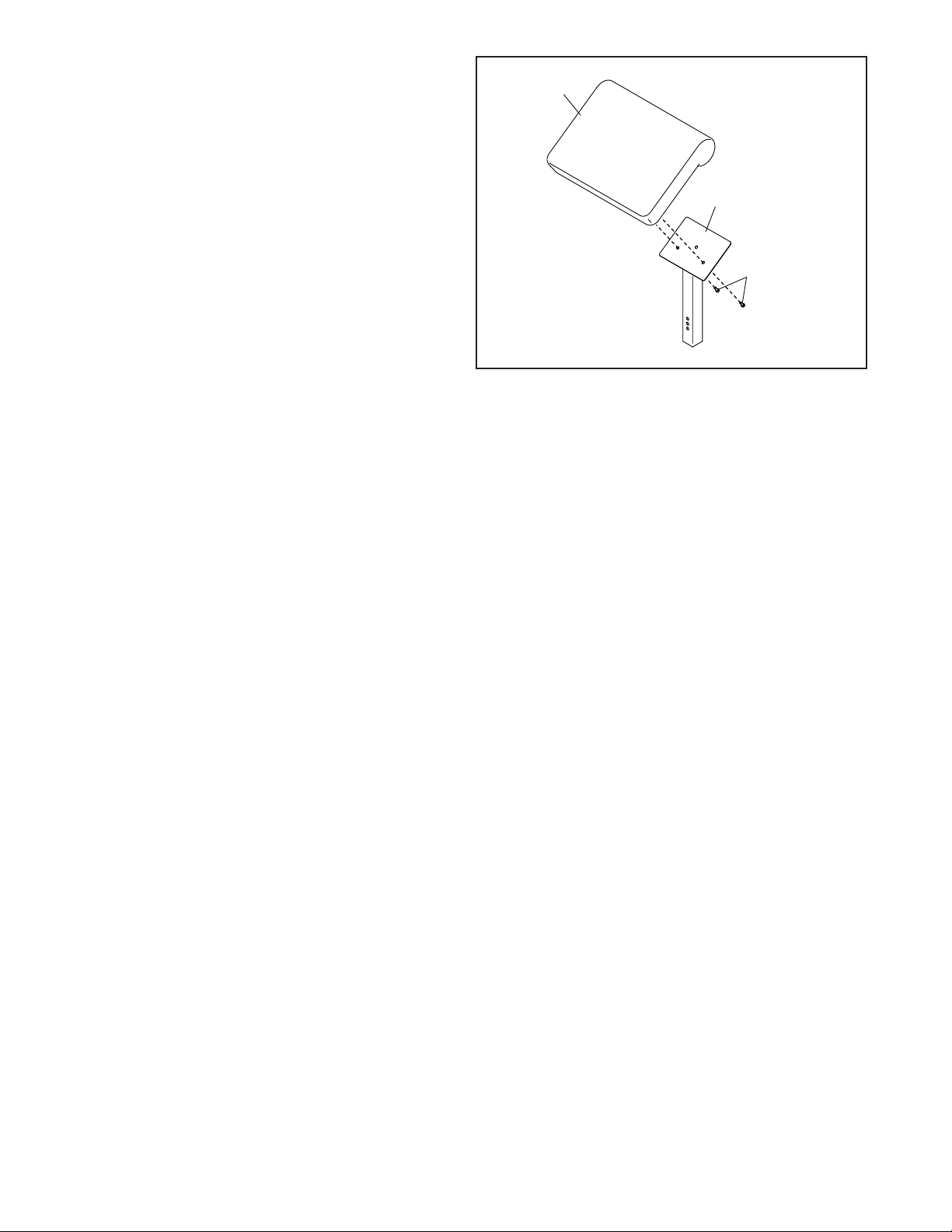
15. Attach the Curl Pad (41) to the Curl Post (27)
with two M6 x 20mm Screws (33). To avoid
damaging the Curl Pad, tighten the Screws
only until the Curl Pad does not move or
feel loose.
16. Make sure that all parts are properly tightened before you use the weight bench. The use of all
remaining parts will be explained in ADJUSTMENT on page 16.
15
41
27
33
15
Page 16
ADJUSTMENT
This section explains how to adjust the weight bench. See the EXERCISE GUIDELINES on page 19
for important information about how to get the most benefit from your exercise program. Also, refer to the
accompanying exercise guide to see the correct form for several exercises.
Make sure that all parts are properly tightened each time you use the weight bench. Replace any worn
parts immediately. The weight bench can be cleaned with a damp cloth and a mild, non-abrasive detergent; do
not use solvents.
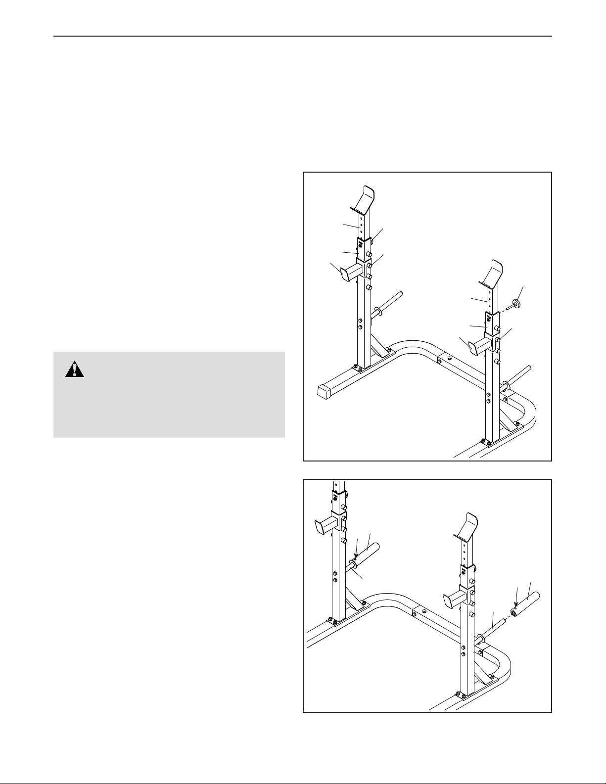
ADJUSTING THE WEIGHT RESTS AND THE
SPOTTERS
To adjust the height of the Weight Rests (5), raise
them to the desired height, and then tighten the
Adjustment Knobs (7) into the Uprights (3). Make
sure that the Weight Rests are at the same
height and that the Adjustment Knobs are fully
tightened into the Uprights.
To adjust the height of the Spotters (6), move the
Spotters to a different set of pegs (A) on the Uprights
(3). Make sure that the Spotters are at the same
height.
5
3
6
7
A
7
5
3
6
A
WARNING: Do not place
more than 310 lbs. (141 kg) on the Weight
Rests (5). Always set both Weight Rests at
the same height, and make sure that the
Adjustment Knobs (7) are fully tightened.
STORING WEIGHTS
You can store your weights (not included) on the two
Storage Tubes (4).
If you plan to store Olympic weights, first slide the
Olympic Adapters (8) onto the Storage Tubes (4).
Then, tighten the M8 x 10mm Set Screws (10) in the
Olympic Adapters.
10
8
4
4
10
8
16
Page 17
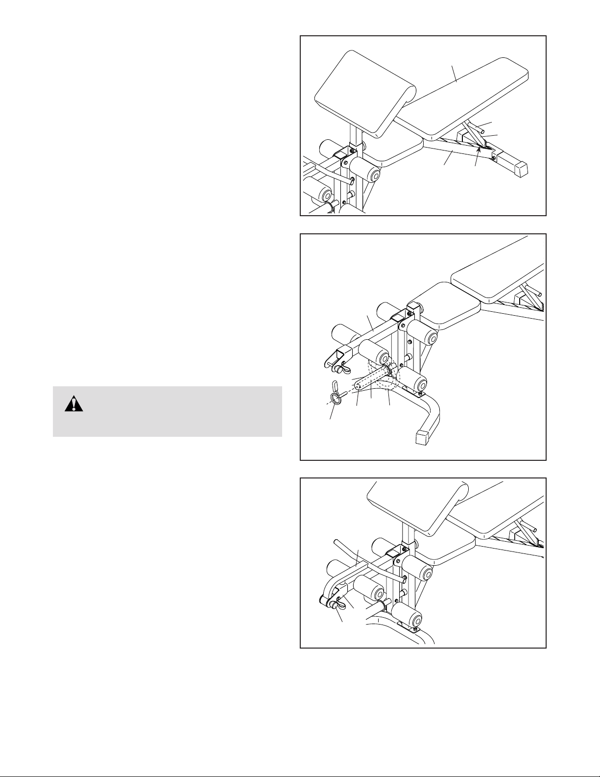
ADJUSTING THE BACKREST
To adjust the position of the Backrest (40), hold the
indicated handle (B) on the Backrest Post (36), raise
or lower the Backrest, and then set the Backrest
Post in one of the slots (C) in the Frame (22). Make
sure that the Backrest Post is fully inserted into
one of the slots.
USING THE LEG LEVER
If you plan to use Olympic weights (not included),
see assembly step 11 on page 13 and attach
the Olympic Adapter (8) to the Weight Tube (45).
To use the Leg Lever (26), slide the desired weights
(D) (not included) onto the Weight Tube (45). Secure
the weights with the Standard Spring Clip (30) or the
Olympic Spring Clip (49). Note: Before using the
Leg Lever, remove the Curl Bar (not shown) and
the Curl Pad (not shown).
26
22
40
B
36
C
WARNING: Do not place more
than 150 lbs. (68 kg) on the Leg Lever (26).
ATTACHING AND REMOVING THE CURL BAR
To attach the Curl Bar (38) to the Leg Lever (26),
fully insert the Curl Bar Pin (54) into the Leg Lever
and the Curl Bar as shown.
When performing exercises that do not require the
Curl Bar (38), pull the Curl Bar Pin (54) out of the
Leg Lever (26), and remove the Curl Bar.
30, 49
54
8
38
26
45
D
17
Page 18
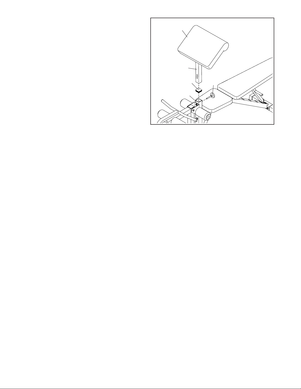
ATTACHING AND REMOVING THE CURL PAD
To attach the Curl Pad (41), remove the 50mm
Square Inner Cap (47) from the Front Leg (25), and
insert the Curl Post (27) into the Front Leg. Then,
tighten the Adjustment Knob (7) into the Front Leg
and into one of the adjustment holes in the Curl Post.
Make sure that the Adjustment Knob is inserted
through one of the adjustment holes.
41
27
When performing exercises that do not require the
Curl Pad (41), remove the Curl Pad and insert the
50mm Square Inner Cap (47) into the Front Leg (25).
25
47
7
18
Page 19

EXERCISE GUIDELINES
FOUR TYPES OF STRENGTH WORKOUTS
Note: A “repetition” is one complete cycle of an
exercise, such as one sit-up. A “set” is a series of
repetitions.
Muscle Building—Work your muscles near their maximum capacity and progressively increase the intensity
of your exercise. Adjust the intensity level of an individual exercise as follows:
• Change the amount of resistance used.
• Change the number of repetitions or sets performed.
Use your own judgment to determine the amount of
resistance that is right for you. Begin with 3 sets of 8
repetitions for each exercise you perform. Rest for 3
minutes after each set. When you can complete 3 sets
of 12 repetitions without difficulty, increase the amount
of resistance.
Toning—Tone your muscles by working them to a
moderate percentage of their capacity. Select a moderate amount of resistance and increase the number of
repetitions in each set. Complete as many sets of 15 to
20 repetitions as possible without discomfort. Rest for
1 minute after each set. Work your muscles by completing more sets rather than by using high amounts of
resistance.
Weight Loss—To lose weight, use a low amount of
resistance and increase the number of repetitions in
each set. Exercise for 20 to 30 minutes, resting for a
maximum of 30 seconds between sets.
Cross Training—Combine strength training and aerobic exercise by following this type of program:
• Strength training workouts on Monday, Wednesday,
and Friday.
• 20 to 30 minutes of aerobic exercise on Tuesday and
Thursday.
• One full day of rest each week to give your body time
to regenerate.
WORKOUT GUIDELINES
workout, and the numbers of repetitions and sets to
complete. Progress at your own pace and be sensitive
to your body’s signals. Follow each workout with at
least one day of rest.
Warming Up—Start with 5 to 10 minutes of stretching and light exercise. A warm-up increases your body
temperature, heart rate, and circulation in preparation
for exercise.
Working Out—Include 6 to 10 different exercises in
each workout. Select exercises for every major muscle
group, emphasizing areas that you want to develop.
To give balance and variety to your workouts, vary the
exercises from workout to workout.
Cooling Down—Finish with 5 to 10 minutes of stretching. Stretching increases the flexibility of your muscles
and helps to prevent post-exercise problems.
EXERCISE FORM
Move through the full range of motion for each exercise and move only the appropriate parts of the body.
Perform the repetitions in each set smoothly and
without pausing. The exertion stage of each repetition should last about half as long as the return stage.
Exhale during the exertion stage of each repetition and
inhale during the return stroke. Never hold your breath.
Rest for a short period of time after each set:
• Muscle Building—Rest for three minutes after each
set.
• Toning—Rest for one minute after each set.
• Weight Loss—Rest for 30 seconds after each set.
STAYING MOTIVATED
For motivation, keep a record of each workout. Write
the date, the exercises performed, the resistance used,
and the numbers of sets and repetitions completed.
Record your weight and key body measurements once
a month. To achieve good results, make exercise a
regular and enjoyable part of your life.
Familiarize yourself with the equipment and learn the
proper form for each exercise. Use your own judgment
to determine the appropriate length of time for each
19
Page 20
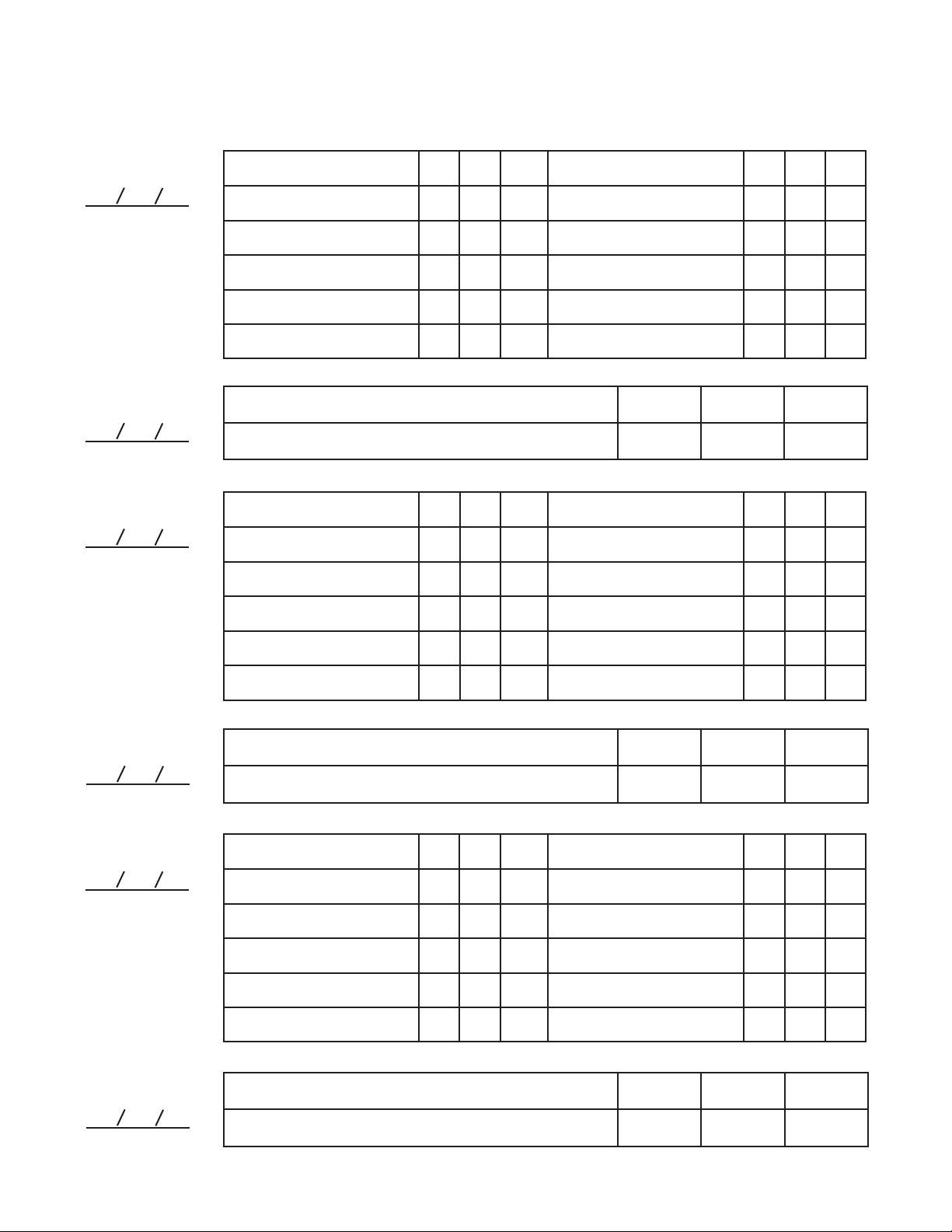
EXERCISE LOG
Make copies of this page, and use the copies to schedule and record your strength and aerobic workouts.
Scheduling and recording your workouts will help you to make exercise a regular and enjoyable part of your life.
Strength
Date:
Aerobic
Date:
Strength
Date:
Exercise Lbs. Sets Reps
1.
2.
3.
4.
5.
Exercise
6.
7.
8.
9.
10.
Lbs. Sets Reps
Exercise Time Distance Speed
Exercise Lbs. Sets Reps
1.
2.
Exercise
6.
7.
Lbs. Sets Reps
Aerobic
Date:
Strength
Date:
3.
4.
5.
8.
9.
10.
Exercise Time Distance Speed
Exercise Lbs. Sets Reps
1.
2.
3.
4.
5.
Exercise
6.
7.
8.
9.
10.
Lbs. Sets Reps
Aerobic
Date:
Exercise Time Distance Speed
20
Page 21

PART LIST
Key No. Qty. Description Key No. Qty. Description
Model No. PFBE60120.0 R0920A
1 1 Right Base
2 1 Left Base
3 2 Upright
4 2 Storage Tube
5 2 Weight Rest
6 2 Spotter
7 3 Adjustment Knob
8 3 Olympic Adapter
9 6 M10 x 20mm Screw
10 3 M8 x 10mm Set Screw
11 2 Upright Bushing
12 2 Weight Rest Bushing
13 2 50mm x 70mm Outer Cap
14 2 Foot
15 20 25mm x 1.5mm Round Inner Cap
16 8 M10 x 65mm Carriage Bolt
17 17 M10 Locknut
18 10 M4 x 19mm Screw
19 18 M10 Washer
20 4 M10 x 75mm Bolt
21 1 Center Base
22 1 Frame
23 1 Front Stabilizer
24 1 Rear Stabilizer
25 1 Front Leg
26 1 Leg Lever
27 1 Curl Post
28 1 M8 x 65mm Bolt
29 4 M10 x 70mm Bolt
30 1 Standard Spring Clip
31 1 25mm x 2.5mm Round Inner Cap
32 1 M8 Locknut
33 6 M6 x 20mm Screw
34 1 25mm Round Outer Cap
35 1 Spacer
36 1 Backrest Post
37 2 Backrest Frame
38 1 Curl Bar
39 1 Seat
40 1 Backrest
41 1 Curl Pad
42 2 Short Pad Tube
43 6 Foam Pad
44 6 Pad Cap
45 1 Weight Tube
46 4 50mm Square Outer Cap
47 4 50mm Square Inner Cap
48 1 19mm Round Inner Cap
49 1 Olympic Spring Clip
50 4 25mm Square Inner Cap
51 1 Bumper
52 2 Curl Bar Bushing
53 2 Backrest Post Bushing
54 1 Curl Bar Pin
55 2 M10 x 170mm Bolt
56 4 M6 x 40mm Screw
57 1 Long Pad Tube
58 2 M8 Washer
59 4 M6 Washer
60 1 M10 x 70mm Bolt Set
* – User’s Manual
* – Exercise Guide
* – Grease Packet
* – Assembly Tool
Note: Specifications are subject to change without notice. See the back cover of this manual for information about
ordering replacement parts. *These parts are not illustrated.
21
Page 22
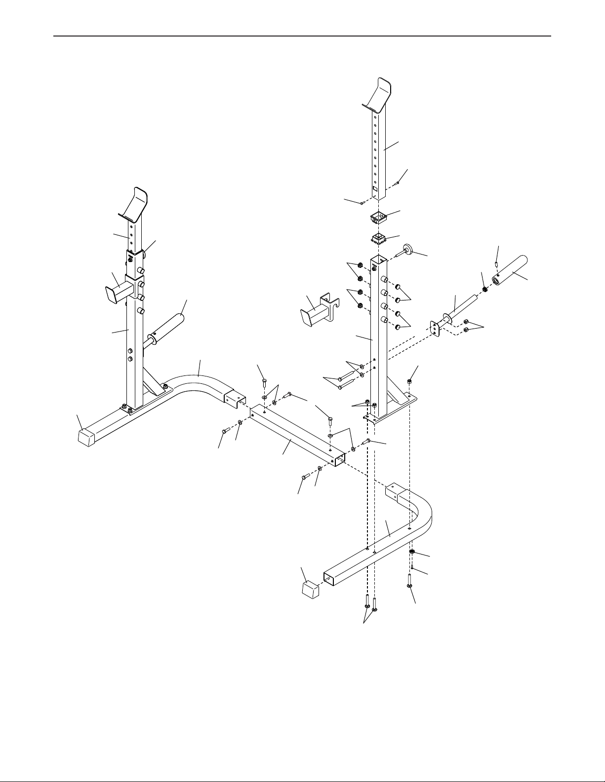
EXPLODED DRAWING A
Model No. PFBE60120.0 R0920A
5
18
18
11
13
5
6
3
7
15
9
19
15
3
19
20
17
19
8
1
9
9
19
6
19
21
9
12
7
4
15
15
17
9
2
10
15
8
17
13
22
14
18
16
16
Page 23
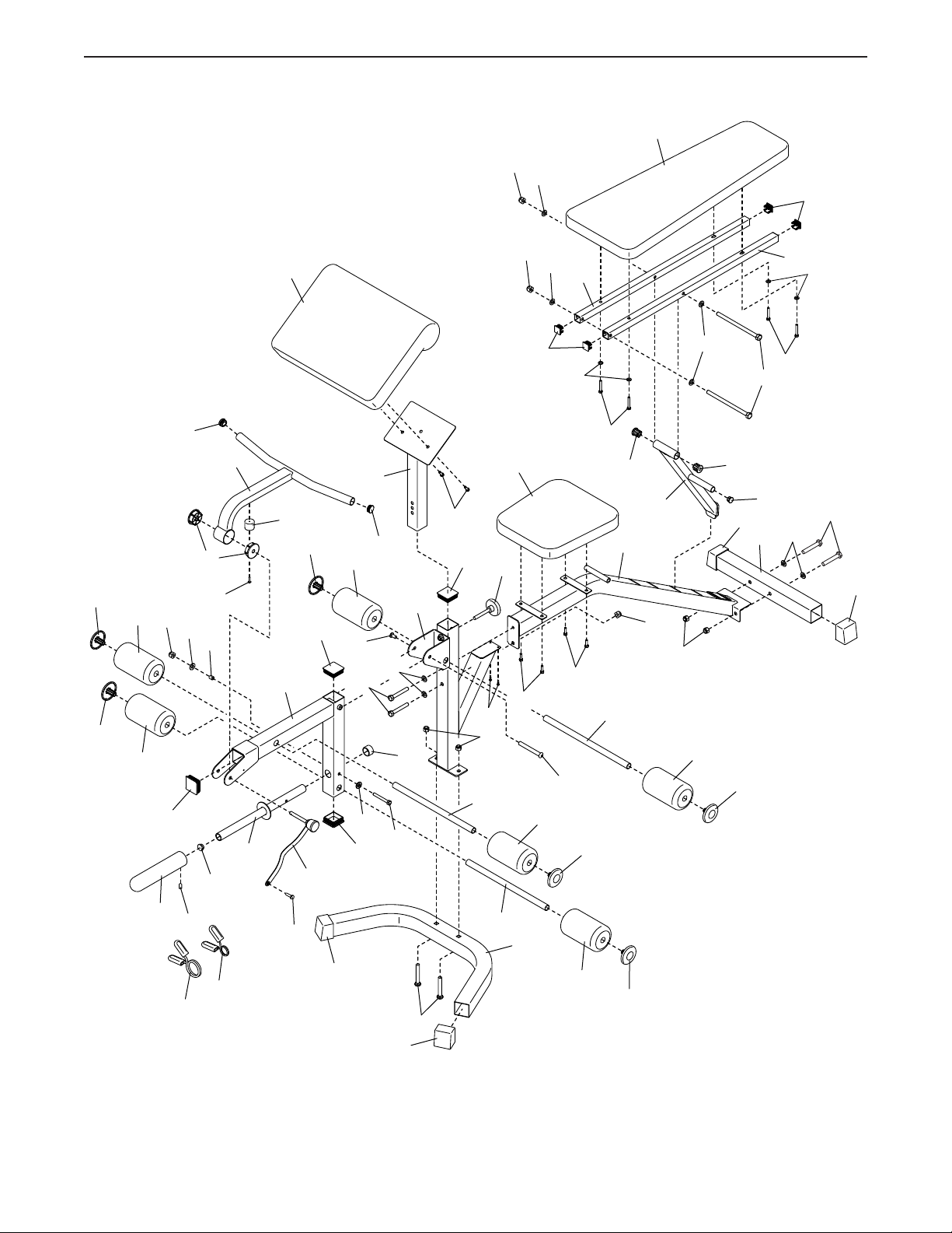
EXPLODED DRAWING B
Model No. PFBE60120.0 R0920A
40
17
19
50
44
44
43
43
32
47
15
58
52
35
18
31
38
45
41
26
51
44
54
47
43
60
29
58
47
27
15
19
28
34
25
33
47
18
42
17
7
39
17
33
50
43
19
60
59
33
37
44
56
57
53
22
36
17
17
43
19
53
46
44
24
55
48
56
37
19
59
29
46
8
10
30
49
18
46
16
46
42
23
43
44
23
Page 24
ORDERING REPLACEMENT PARTS
To order replacement parts, please see the front cover of this manual. To help us assist you, be prepared to
provide the following information when contacting us:
• the model number and serial number of the product (see the front cover of this manual)
• the name of the product (see the front cover of this manual)
• the key number and description of the replacement part(s) (see the PART LIST and the EXPLODED DRAWING
near the end of this manual)
LIMITED WARRANTY
IMPORTANT: To protect your fitness equipment with an extended service plan, see page 5.
ICON Health & Fitness, Inc. (ICON) warrants this product to be free from defects in workmanship and
material, under normal use and service conditions. Parts and labor are warranted for ninety (90) days from
the date of purchase.
This warranty extends only to the original purchaser (customer) and is not transferrable. ICON’s obligation under this warranty is limited to repairing or replacing, at ICON’s option, the product through one of
its authorized service providers. All repairs for which warranty claims are made must be preauthorized by
ICON. If replacement parts are shipped while the product is under warranty, the customer will be responsible for a minimal handling charge. For in-home service, the customer may be responsible for a minimal
trip charge. This warranty does not extend to freight damage to the product. This warranty will automatically be voided by the following conditions: (1) if the product is used as a store display model, (2) if the
product is purchased or transported outside the USA, (3) if all instructions and warnings in this manual are
not followed, (4) if the product is abused or improperly or abnormally used, or (5) if the product is used for
commercial or rental purposes. No other warranty beyond that specically set forth above is authorized
by ICON.
ICON is not responsible or liable for the following damages: (1) indirect, special, or consequential damages arising out of or in connection with the use or performance of the product; (2) damages with respect
to any economic loss, loss of property, loss of revenues or prots, loss of enjoyment or use, or costs of
removal or installation; or (3) other consequential damages of any kind. Some states do not allow the
exclusion or limitation of incidental or consequential damages. Accordingly, the above limitation may not
apply to the customer.
The warranty extended hereunder is in lieu of any and all other warranties, and any implied warranties of
merchantability or tness for a particular purpose are limited in their scope and duration to the terms set
forth herein. Some states do not allow limitations on how long an implied warranty lasts. Accordingly, the
above limitation may not apply to the customer. This warranty provides specic legal rights; the customer
may have other rights that vary from state to state.
For warranty service, please call the telephone number on the front cover of this manual. Please be prepared to provide the model number and serial number of the product (see the front cover of this manual).
ICON Health & Fitness, Inc., 1500 S. 1000 W., Logan, UT 84321-9813
Part No. 423417 R0920A Printed in China © 2020 ICON Health & Fitness, Inc.
 Loading...