

Page 1

CAUTION
Read all precautions and instruc
tions in this manual before using
this equipment. Save this manual
for future reference.
Model No. PFEVBE09240
Serial No.
Write the serial number in the
space above for future reference.
USER’S MANUAL
Part No. 221582 R1204A Printed in China © 2004 ICON IP, Inc.
QUESTIONS?
As a manufacturer, we are committed to providing complete
customer satisfaction. If you
have questions, or if there are
missing or damaged parts,
please call:
Or write:
ICON Health & Fitness Ltd.
Unit 4
Revie Road Industrial Estate
Revie Road
Leeds, LS11 8JG
UK
email: csuk@iconeurope.com
ORDERING REPLACEMENT PARTS
If you encounter any problems with this product, or if you need to order replacement parts, contact the ICON
Health & Fitness, Ltd. office, or write:
ICON Health & Fitness, Ltd.
Unit 4, Revie Road Industrial Estate
Revie Road
Leeds, LS11 8JG
UK
Tel:
Outside the UK: 0 (044) 113 387 7133
Fax: 0 (044) 113 387 7125
To help us assist you, please be prepared to give the following information:
• The MODEL NUMBER of the product (PFEVBE09240)
• The NAME of the product (PROFORM C600 weight bench)
• The SERIAL NUMBER of the product (see the front cover of this manual)
• The KEY NUMBER and DESCRIPTION of the desired part(s) (see the PART LIST and the EXPLODED
DRAWING on pages 10 and 11 of this manual)
08457 089 009
08457 089 009
Serial Number Decal (Under Seat)
Page 2
11
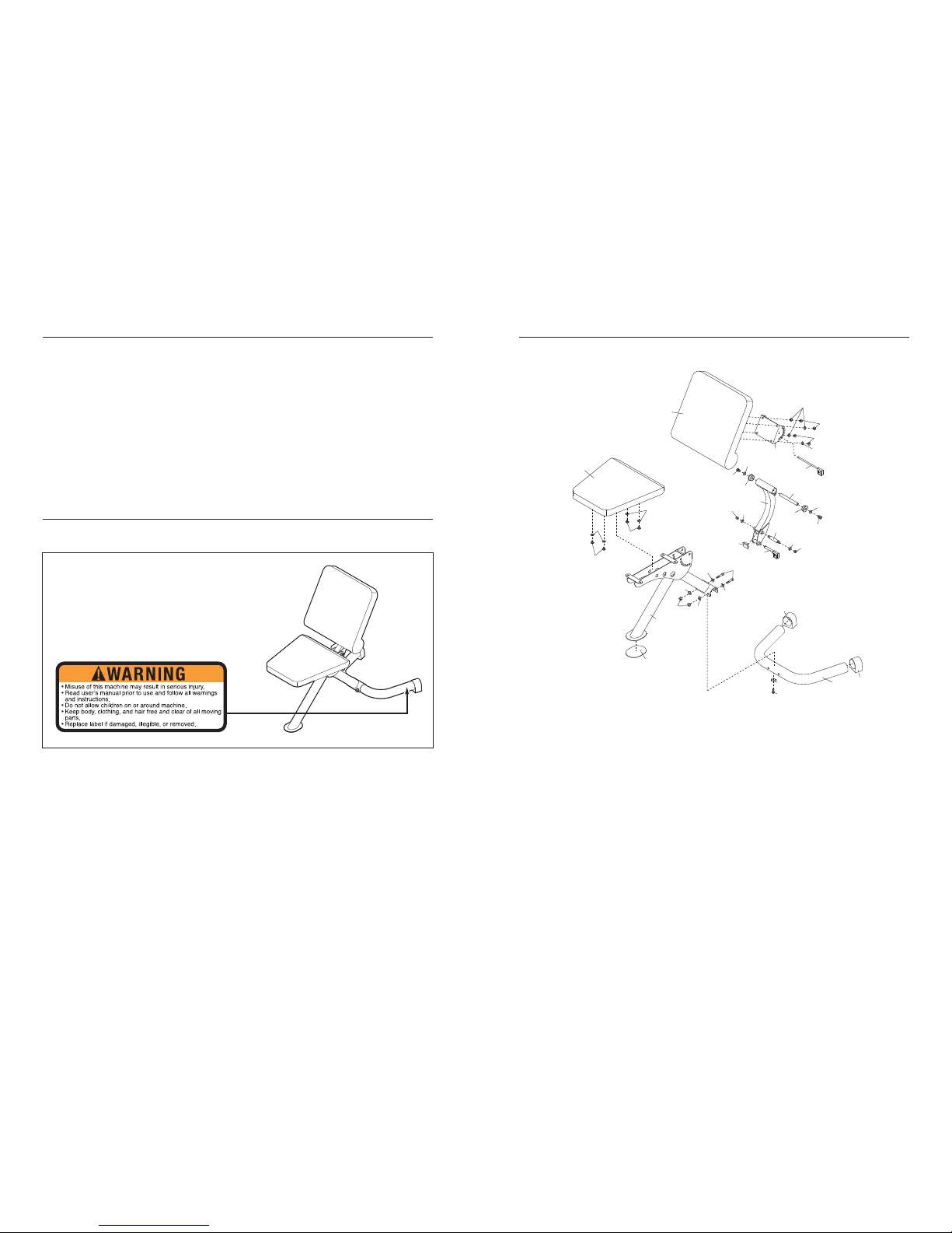
EXPLODED DRAWING—Model No. PFEVBE09240 R1204A
2
22
19
19
17
18
17
18
6
7
17
5
8
5
17
20
20
21
9
3
10
4
11
17
17
18
18
15
21
19
19
18
18
13
21
1
12
12
16
14
2
WARNING DECAL PLACEMENT
WARNING DECAL PLACEMENT . . . . . . . . . . . . . . . . . . . . . . . . . . . . . . . . . . . . . . . . . . . . . . . . . . . . . . . . . . . . . 2
IMPORTANT PRECAUTIONS . . . . . . . . . . . . . . . . . . . . . . . . . . . . . . . . . . . . . . . . . . . . . . . . . . . . . . . . . . . . . . . . 3
BEFORE YOU BEGIN . . . . . . . . . . . . . . . . . . . . . . . . . . . . . . . . . . . . . . . . . . . . . . . . . . . . . . . . . . . . . . . . . . . . . . 4
PART IDENTIFICATION CHART . . . . . . . . . . . . . . . . . . . . . . . . . . . . . . . . . . . . . . . . . . . . . . . . . . . . . . . . . . . . . .5
ASSEMBLY . . . . . . . . . . . . . . . . . . . . . . . . . . . . . . . . . . . . . . . . . . . . . . . . . . . . . . . . . . . . . . . . . . . . . . . . . . . . . . 6
ADJUSTMENTS . . . . . . . . . . . . . . . . . . . . . . . . . . . . . . . . . . . . . . . . . . . . . . . . . . . . . . . . . . . . . . . . . . . . . . . . . . . 9
PART LIST . . . . . . . . . . . . . . . . . . . . . . . . . . . . . . . . . . . . . . . . . . . . . . . . . . . . . . . . . . . . . . . . . . . . . . . . . . . . . .10
EXPLODED DRAWING . . . . . . . . . . . . . . . . . . . . . . . . . . . . . . . . . . . . . . . . . . . . . . . . . . . . . . . . . . . . . . . . . . . . 11
ORDERING REPLACEMENT PARTS . . . . . . . . . . . . . . . . . . . . . . . . . . . . . . . . . . . . . . . . . . . . . . . . . .Back Cover
TABLE OF CONTENTS
The decal shown here has been placed on the
weight bench. If the decal is missing, or if it is
not legible, please call our Customer Service
Department and order a free replacement decal
(see the back cover of this manual). Apply the
decal in the location shown.
PROFORM is a registered trademark of ICON IP
, Inc.
Page 3

10
Note: “#” indicates a non-illustrated part. Specifications are subject to change without notice. See the back cover
of this manual for information about ordering replacement parts.
Key No. Qty. Description Key No. Qty. Description
1 1 Base
2 1 Frame
3
1 Backrest Arm
4
1 Backrest Frame
5 2 Bushing
6 1 Seat
7 1 Backrest
8 1 Pivot Rod
9 1 Shaft Bolt
10 1 Short Pin
11 1 Long Pin
12 2 Base Endcap
13 1 38mm Inner Cap
14 1 M5 x 15mm Bolt
15
1 Frame Pad
16
1 Base Pad
17 10 M8 x 20mm Screw
18 10 M8 Washer
19 4 M10 Curved Washer
20 2 M10 Washer
21 4 M10 Nut
22 2 M10 x 80mm Bolt
# 1 User’s Manual
PART LIST—Model No. PFEVBE09240 R1204A
1. Read all instructions in this manual before
using the weight bench. Use the weight
bench only as described in this manual.
2. It is the responsibility of the owner to ensure
that all users of the weight bench are adequately informed of all precautions.
3. The weight bench is intended for home use
only. Do not use the weight bench in any
commercial, rental, or institutional setting.
4. Use the weight bench only on a level surface.
Cover the floor beneath the weight bench to
protect the floor.
5. Make sure all parts are properly tightened
each time the weight bench is used. Replace
any worn parts immediately.
6. Keep children under 12 and pets away from
the weight bench at all times.
7. Keep hands and feet away from moving parts.
8. Always wear athletic shoes for foot protection while exercising.
9. Keep the weight bench indoors, away from
moisture and dust. Do not put the weight
bench in a garage or covered patio, or near
water.
10. The weight bench is designed to support a
maximum user weight of 135 kg (300 lbs.),
and a maximum total weight of 185 kg (410
lbs.).
11. Always make sure the pins are fully inserted
into the weight bench frames before using
the weight bench.
12. If you feel pain or dizziness at any time while
exercising, stop immediately and begin cooling down.
WARNING:Before beginning this or any exercise program, consult your physician. This
is especially important for persons over the age of 35 or persons with pre-existing health problems.
Read all instructions before using. ICON assumes no responsibility for personal injury or property
damage sustained by or through the use of this product.
WARNING: To reduce the risk of serious injury, read the following important precautions
before using the weight bench.
IMPORTANT PRECAUTIONS
3
Page 4

This section explains how to adjust the weight bench. See the accompanying exercise guide to see the correct
form for each exercise.
Make sure all parts are properly tightened each time the weight bench is used. Replace any worn parts immediately
. The weight bench can be cleaned with a damp cloth and a mild, non-abrasive detergent. Do not use solvents.
9
ADJUSTMENTS
ADJUSTING THE BACKREST FRAME
Hold the Backrest (7) with one hand and remove the
Long Pin (11). Move the Backrest to the desired position and reinsert the Long Pin into the Backrest
Frame (4) and the Backrest Arm (3).
4
3
7
11
WARNING:Make sure the Long
Pin (11) is fully inserted into the Backrest
Frame (4) and the Backrest Arm (3) before
using the weight bench.
ADJUSTING THE BACKREST ARM
Hold the Backrest (7) with one hand and remove the
Short Pin (10). Move the Backrest to the desired position and reinsert the Short Pin into the Frame (2) and
the Backrest Arm (3).
3
2
7
10
WARNING:Make sure the Short
Pin (10) is fully inserted into the Frame (2) and
the Backrest Arm (3) before using the weight
bench.
4
Backrest
Base
Frame
Seat
BEFORE YOU BEGIN
Thank you for selecting the versatile PROFORM
®
C600 weight bench. The weight bench offers a selection of weight stations designed to develop the major
muscle group of the upper body. Whether your goal is
to tone your body
, build dramatic muscle size and
strength, or improve your cardiovascular system, the
weight bench will help you to achieve the specific
results you want.
For your benefit, read this manual carefully before
using the weight bench. If you have questions after
reading this manual, please call our Customer Service
Department at 0845 089 009. To help us assist you,
please note the product model number and serial
number before calling. The model number is
PFEVBE09240.
The serial number can be found on a
decal attached to the weight bench (see the front
cover of this manual).
Before reading further, please review the drawing
below and familiarize yourself with the parts that are
labeled.
ASSEMBLED
DIMENSIONS:
Height: 104 cm (41 in.)
Width: 66 cm (26 in.)
Depth: 48 cm (19 in.)
Page 5

8
5. Attach the Seat (6) to the Frame (2) with four M8
x 20mm Screws (17) and four M8 Washers (18).
6. Make sure all parts are properly tightened
before the weight bench is used.
5
6
2
18
18
18
17
17
17
5
M10 Washer (20)
M10 Nut (21)
M8 Washer (18)
M10 Curved Washer (19)
M10 x 80mm Bolt (22)
M8 x 20mm Screw (17)
PART IDENTIFICATION CHART
See the drawings below to identify small parts used in assembly
. The number in parentheses by each drawing is
the key number of the part, from the PART LIST on page 10 of this manual.
Note: Some small parts may have
been pre-attached. If a part is not in the parts bag, check to see if it has been pre-attached.
Page 6

7
2. Attach the Frame (2) to the Base (1) with two
M10 x 80mm Bolts (22), four M10 Curved
W
ashers (19), and two M10 Nuts (21).
4.
Attach the Backrest (7) to the Backrest Frame (4)
with four M8 x 20mm Screws (17) and four M8
Washers (18).
Full insert the Long Pin (1
1) into the Backrest
Frame (4) and the Backrest Arm (3).
3. Attach the Backrest Arm (3) to the Frame (2) with
the Shaft Bolt (9), two M10 Washers (20), and
two M10 Nuts (21).
Fully insert the Short Pin (10) into the Frame (2)
and into the lower tube in the Backrest Arm (3).
2
3
4
1
21
2
19
19
22
3
9
Lower
Tube
10
21
21
20
20
2
7
4
3
18
17
11
6
1.
Press two Base Endcaps (12) onto the Base (1).
1
Before beginning assembly, make sure you
understand the information in the box
above.
12
12
1
Before beginning assembly, carefully read the
following information and instructions:
•
Assembly requires two persons.
• T
ighten all parts as you assemble them, unless
instructed to do otherwise.
• As you assemble the weight bench, make sure all
parts are oriented as shown in the drawings.
• Place all parts in a cleared area and remove the
packing materials. Do not dispose of the packing
materials until assembly is completed.
• For help identifying small parts, use the PART
IDENTIFICATION CHART on page 5.
The following tools (not included) are required
for assembly:
• Two adjustable wrenches
• One rubber mallet
• One standard screwdriver
• One Phillips screwdriver
Make Things Easier for Yourself
Everything in this manual is designed to ensure
that the weight bench can be assembled successfully by anyone. Most people find that by
setting aside plenty of time, assembly will go
smoothly.
ASSEMBLY
 Loading...