

ProForm 980 CS PFTL99908.2, 980 CS User Manual
With Universal Dock for iPod ®
www.proform.com
Model No. PFTL99908.2
Serial No.
Write the serial number in the space
above for reference.
Serial Number
Decal
QUESTIONS?
If you have questions, or if parts are
damaged or missing, DO NOT CON-
TACT THE STORE; please contact
Customer Care.
USER'S MANUAL
IMPORTANT: Please register this
product (see the limited warranty
on the back cover of this manual)
before contacting Customer Care.
CALL TOLL-FREE:
1-888-533-1333
Mon.-Fri. 6 a.m.-6 p.m. MT
Sat. 8 a.m.-4 p.m. MT
ON THE WEB:
www.proformservice.com
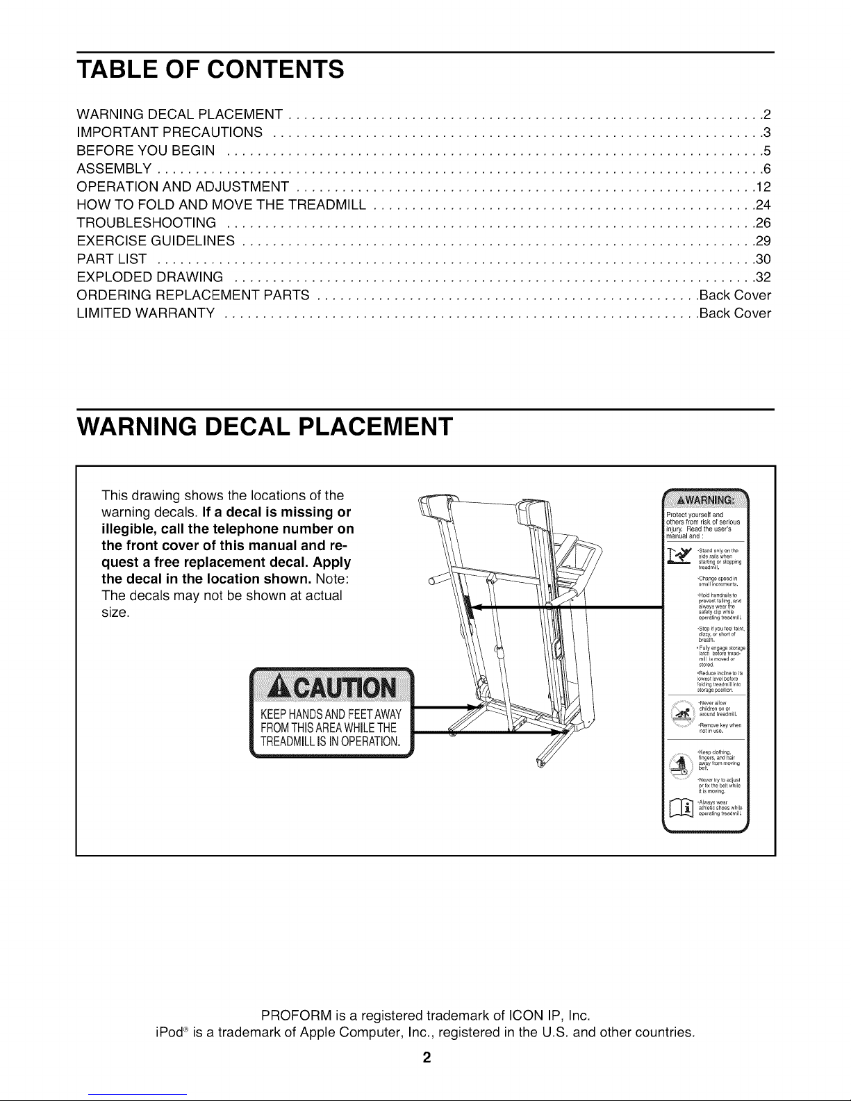
TABLE OF CONTENTS
WARNING DECAL PLACEMENT .............................................................. 2
IMPORTANT PRECAUTIONS ................................................................ 3
BEFORE YOU BEGIN ...................................................................... 5
ASSEMBLY ............................................................................... 6
OPERATION AND ADJUSTMENT ............................................................ 12
HOW TO FOLD AND MOVE THE TREADMILL .................................................. 24
TROUBLESHOOTING ..................................................................... 26
EXERCISE GUIDELINES ................................................................... 29
PART LIST .............................................................................. 30
EXPLODED DRAWING .................................................................... 32
ORDERING REPLACEMENT PARTS .................................................. Back Cover
LIMITED WARRANTY .............................................................. Back Cover
WARNING DECAL PLACEMENT
This drawing shows the locations of the
warning decals. If a decal is missing or
illegible, call the telephone number on
the front cover of this manual and re-
quest a free replacement decal. Apply
the decal in the location shown. Note:
The decals may not be shown at actual
size.
Protect yourself and
others from risk of serious
injury. Read the user's
manual and :
sde fails when
• Stand only on the
,Hold hand[a_ls to
prevent falling, and
always we_r the
safety cllp while
operating treadmill.
• Stop _fyou _eel rant,
d_zzy, or short of
breath.
= Fully engage storage
latch before tread-
mill is moved or
sto_ed
•Reduce incline to ts
lowest level before
folding treadm II _to
storage posit on
•Never allow
..... children on of
•_ ..... d tleadmill,
•Remove key when
notn use.
• Never t_y to adjust
or fix the belt wNle
it is movEmg.
athlet;c shoes whle
[_ -Always wear
operating treadmill.
in
PROFORM is a registered trademark of ICON IP, Inc.
iPod®is a trademark of Apple Computer, Inc., registered in the U.S. and other countries.
2

IMPORTANT PRECAUTIONS
WARNING: To reduce the risk of serious injury, read all important precautions and in-
structions in this manual and all warnings on your treadmill before using your treadmill. ICON as-
sumes no responsibility for personal injury or property damage sustained by or through the use of
this product.
.
Before beginning any exercise program, con-
sult your physician. This is especially impor-
tant for persons over age 35 or persons with
pre-existing health problems.
.
It is the responsibility of the owner to ensure
that all users of this treadmill are adequately
informed of all warnings and precautions.
.
Use the treadmill only as described.
4.
Place the treadmill on a level surface, with at
least 8 ft. (2.4 m) of clearance behind it and 2
ft. (0.6 m) on each side. Do not place the
treadmill on any surface that blocks air open-
ings. To protect the floor or carpet from dam-
age, place a mat under the treadmill.
.
Keep the treadmill indoors, away from mois-
ture and dust. Do not put the treadmill in a
garage or covered patio, or near water.
of carrying 15 or more amps. No other appli-
ance should be on the same circuit. Do not
use an extension cord.
12.
Use only a single-outlet surge suppressor that
meets all of the specifications described on
page 12. To purchase a surge suppressor, see
your local PROFORM dealer or call the tele-
phone number on the front cover of this man-
ual and order part number 146148, or see your
local electronics store.
13.
Failure to use a properly functioning surge
suppressor could result in damage to the con-
trol system of the treadmill. If the control sys-
tem is damaged, the walking belt may slow,
accelerate, or stop unexpectedly, which may
result in a fall and serious injury.
14.
Keep the power cord and the surge suppres-
sor away from heated surfaces.
.
Do not operate the treadmill where aerosol
products are used or where oxygen is being
administered.
.
Keep children under age 12 and pets away
from the treadmill at all times.
.
The treadmill should be used only by per-
sons weighing 350 Ibs. (159 kg) or less.
.
Never allow more than one person on the
treadmill at a time.
10.
Wear appropriate exercise clothes when
using the treadmill. Do not wear loose
clothes that could become caught in the 18.
treadmill. Athletic support clothes are recom-
mended for both men and women. Always
wear athletic shoes. Never use the treadmill
with bare feet, wearing only stockings, or in 19.
sandals.
11.
When connecting the power cord (see page
12), plug the power cord into a surge sup-
pressor (not included) and plug the surge
suppressor into a grounded circuit capable
15.
Never move the walking belt while the power
is turned off. Do not operate the treadmill if
the power cord or plug is damaged, or if the
treadmill is not working properly. (See TROU-
BLESHOOTING on page 26 if the treadmill is
not working properly.)
16.
Read, understand, and test the emergency
stop procedure before using the treadmill (see
HOW TO TURN ON THE POWER on page 14).
17.
Never start the treadmill while you are stand-
ing on the walking belt. Always hold the
handrails while using the treadmill.
The treadmill is capable of high speeds.
Adjust the speed in small increments to
avoid sudden jumps in speed.
The pulse sensor is not a medical device.
Various factors, including the user's move-
ment, may affect the accuracy of heart rate
readings. The pulse sensor is intended only
as an exercise aid in determining heart rate
trends in general.
20.Neverleavethetreadmillunattendedwhileit 24.
isrunning.Alwaysremovethekey,unplug
thepowercord,andswitchthereset/offcir-
cuitbreakertotheoff positionwhenthe 25.
treadmillisnotin use.(Seethedrawingon
page5for the location of the circuit breaker.)
21. Do not attempt to raise, lower, or move the
treadmill until it is properly assembled. (See
ASSEMBLY on page 6, and HOW TO FOLD
AND MOVE THE TREADMILL on page 24.)
You must be able to safely lift 45 Ibs. (20 kg)
to raise, lower, or move the treadmill.
26.
22. When folding or moving the treadmill, make
sure that the storage latch is holding the
frame securely in the storage position.
23. Never insert any object into any opening on
the treadmill.
SAVE THESE INSTRUCTIONS
Inspect and properly tighten all parts of the
treadmill regularly.
DANG ER: Always unplug the power
cord immediately after use, before cleaning the
treadmill, and before performing the mainte-
nance and adjustment procedures described in
this manual. Never remove the motor hood un-
less instructed to do so by an authorized ser-
vice representative. Servicing other than the
procedures in this manual should be performed
by an authorized service representative only.
This treadmill is intended for in-home use
only. Do not use this treadmill in a commer-
cial, rental, or institutional setting.
4
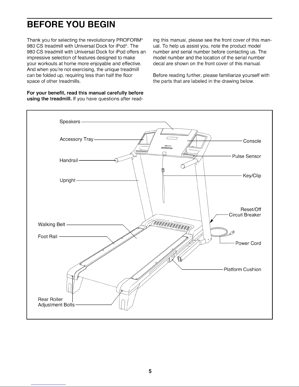
BEFORE YOU BEGIN
Thank you for selecting the revolutionary PROFORM ®
980 CS treadmill with Universal Dock for iPod®.The
980 CS treadmill with Universal Dock for iPod offers an
impressive selection of features designed to make
your workouts at home more enjoyable and effective.
And when you're not exercising, the unique treadmill
can be folded up, requiring less than half the floor
space of other treadmills.
For your benefit, read this manual carefully before
using the treadmill. Ifyou have questions after read-
Speakers
Accessory Tray
Handrail
Upright
ing this manual, please see the front cover of this man-
ual. To help us assist you, note the product model
number and serial number before contacting us. The
model number and the location of the serial number
decal are shown on the front cover of this manual.
Before reading further, please familiarize yourself with
the parts that are labeled in the drawing below.
Console
Pulse Sensor
Key/Clip
Walking Belt
Foot Rail
Rear Roller
Adjustment Bolts
Reset/Off
Breaker
-- Power Cord
Platform Cushion
5
ASSEMBLY
To hire an authorized service technician to assemble the treadmill, call 1-800-445-2480.
Assembly requires two persons. Set the treadmill in a cleared area and remove all packing materials. Do not
dispose of the packing materials until assembly is completed. Note: The underside of the treadmill walking
belt is coated with high-performance lubricant. During shipping, some lubricant may be transferred to the top of
the walking belt or the shipping carton. This is normal and does not affect treadmill performance. If there is lubri-
cant on top of the walking belt, simply wipe off the lubricant with a soft cloth and a mild, non-abrasive cleaner.
Assembly requires the included hex keys ]_and your own Phillips screwdriver
adjustable wrench _, needlenose pliers _, and rubber mallet _.
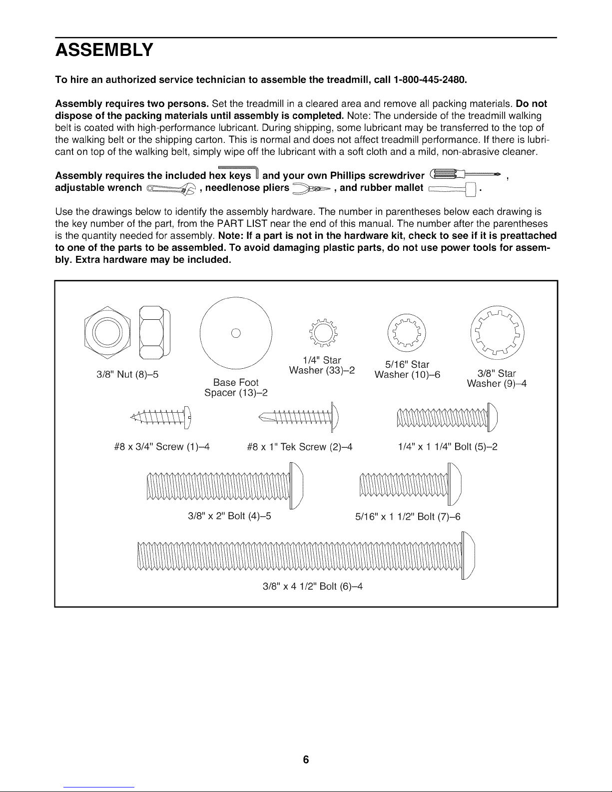
Use the drawings below to identify the assembly hardware. The number in parentheses below each drawing is
the key number of the part, from the PART LIST near the end of this manual. The number after the parentheses
is the quantity needed for assembly. Note: If a part is not in the hardware kit, check to see if it is preattached
to one of the parts to be assembled. To avoid damaging plastic parts, do not use power tools for assem-
bly. Extra hardware may be included.
o o C>
1/4" Star 5/16" Star
3/8" Nut (8)-5
#8 x 3/4" Screw (1)-4 #8 x 1" Tek Screw (2)-4 1/4" x 1 1/4" Bolt (5)-2
Base Foot
Spacer (13)-2
3/8" x 2" Bolt (4)-5
Washer (33)-2 Washer (10)-6 3/8" Star
5/16" x 1 1/2" Bolt (7)-6
3/8" x 4 1/2" Bolt (6)-4
Washer (9)-4
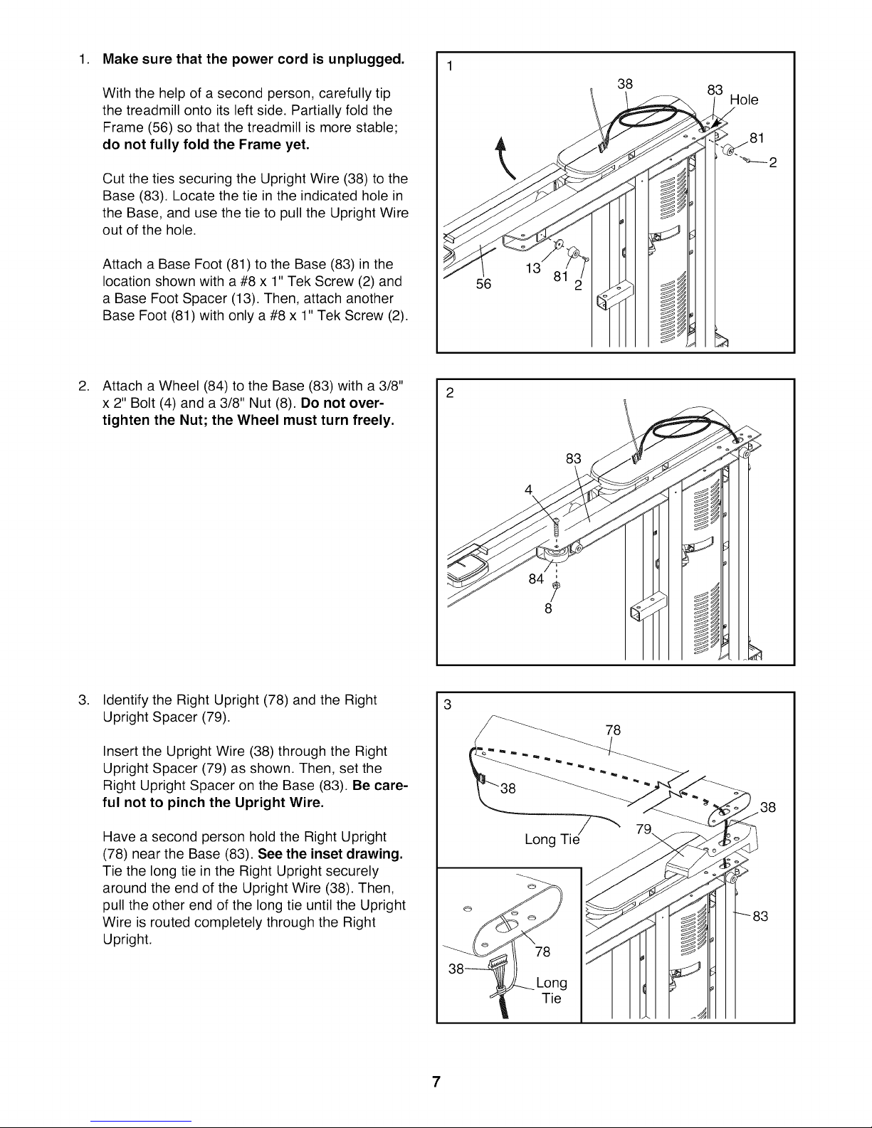
1. Make sure that the power cord is unplugged.
With the help of a second person, carefully tip
the treadmill onto its left side. Partially fold the
Frame (56) so that the treadmill is more stable;
do not fully fold the Frame yet.
Cut the ties securing the Upright Wire (38) to the
Base (83). Locate the tie in the indicated hole in
the Base, and use the tie to pull the Upright Wire
out of the hole.
38
Hole
Attach a Base Foot (81) to the Base (83) in the
location shown with a #8 x 1" Tek Screw (2) and
a Base Foot Spacer (13). Then, attach another
Base Foot (81) with only a #8 x 1" Tek Screw (2).
.
Attach a Wheel (84) to the Base (83) with a 3/8"
x 2" Bolt (4) and a 3/8" Nut (8). Do not over-
tighten the Nut; the Wheel must turn freely.
13
56
83
4
84
8
.
Identify the Right Upright (78) and the Right
Upright Spacer (79).
Insert the Upright Wire (38) through the Right
Upright Spacer (79) as shown. Then, set the
Right Upright Spacer on the Base (83). Be care-
ful not to pinch the Upright Wire.
Have a second person hold the Right Upright
(78) near the Base (83). See the inset drawing.
Tie the long tie in the Right Upright securely
around the end of the Upright Wire (38). Then,
pull the other end of the long tie until the Upright
Wire is routed completely through the Right
Upright.
78
38
79
Long Tid
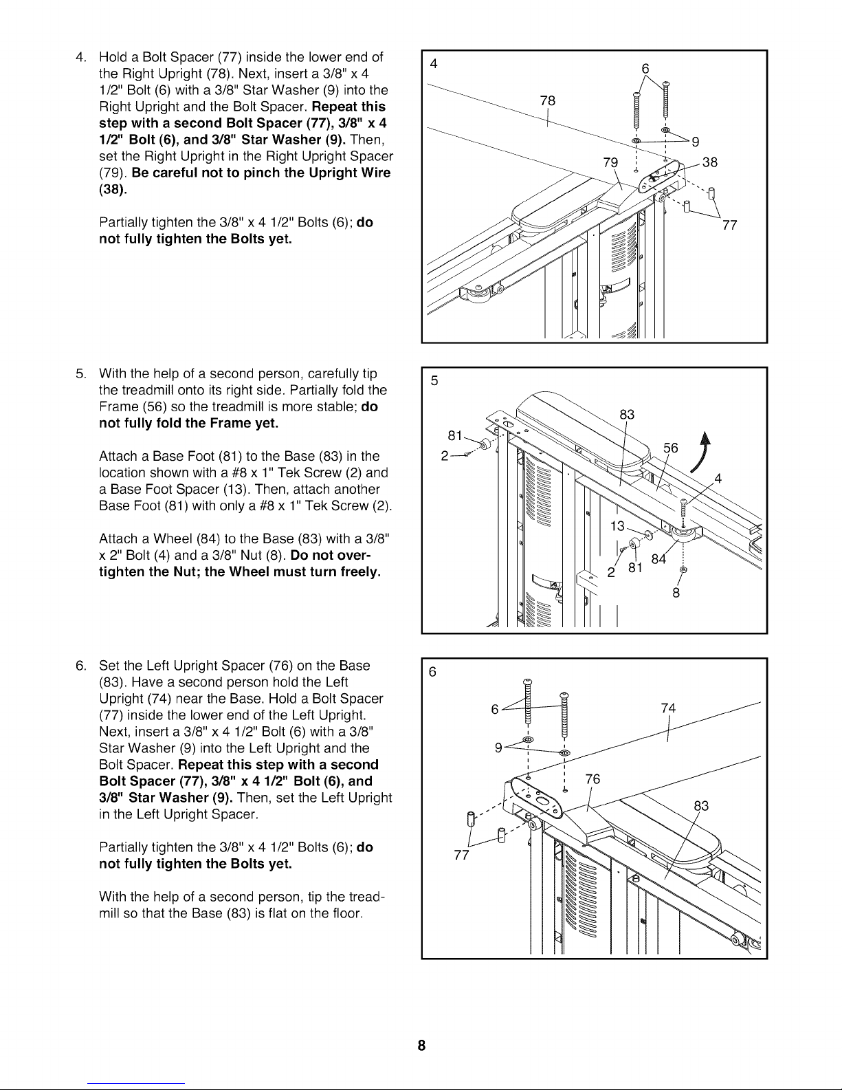
.
Hold a Bolt Spacer (77) inside the lower end of
the Right Upright (78). Next, insert a 3/8" x 4
1/2" Bolt (6) with a 3/8" Star Washer (9) into the
Right Upright and the Bolt Spacer. Repeat this
step with a second Bolt Spacer (77), 3/8" x 4
1/2" Bolt (6), and 3/8" Star Washer (9). Then,
set the Right Upright in the Right Upright Spacer
(79). Be careful not to pinch the Upright Wire
(38).
4
78
79 38
Partially tighten the 3/8" x 4 1/2" Bolts (6); do
not fully tighten the Bolts yet.
.
With the help of a second person, carefully tip
the treadmill onto its right side. Partially fold the
Frame (56) so the treadmill is more stable; do
not fully fold the Frame yet.
Attach a Base Foot (81) to the Base (83) in the
location shown with a #8 x 1" Tek Screw (2) and
a Base Foot Spacer (13). Then, attach another
Base Foot (81) with only a #8 x 1" Tek Screw (2).
Attach a Wheel (84) to the Base (83) with a 3/8"
x 2" Bolt (4) and a 3/8" Nut (8). Do not over-
tighten the Nut; the Wheel must turn freely.
83
77
4
84
1
8
.
Set the Left Upright Spacer (76) on the Base
(83). Have a second person hold the Left
Upright (74) near the Base. Hold a Bolt Spacer
(77) inside the lower end of the Left Upright.
Next, insert a 3/8" x 4 1/2" Bolt (6) with a 3/8"
Star Washer (9) into the Left Upright and the
Bolt Spacer. Repeat this step with a second
Bolt Spacer (77), 3/8" x 4 1/2" Bolt (6}, and
3/8" Star Washer (9). Then, set the Left Upright
in the Left Upright Spacer.
Partially tighten the 3/8" x 4 1/2" Bolts (6); do
not fully tighten the Bolts yet.
With the help of a second person, tip the tread-
mill so that the Base (83) is flat on the floor.
74
83
77
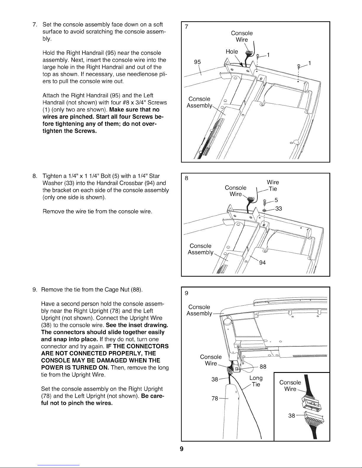
Settheconsoleassemblyfacedownonasoft
7. 7
surfacetoavoidscratchingtheconsoleassem-
bly.
Console
Wire
HoldtheRightHandrail(95)neartheconsole
assembly.Next,inserttheconsolewireintothe
largeholeintheRightHandrailandoutofthe
topasshown.Ifnecessary,useneedlenosepli-
erstopulltheconsolewireout.
AttachtheRightHandrail(95)andtheLeft
Handrail(notshown)withfour#8x3/4"Screws
(1)(onlytwoareshown).Makesurethatno
wiresarepinched.StartallfourScrewsbe-
foretighteninganyof them;donotover-
tightentheScrews.
.
Tighten a 1/4" x 1 1/4" Bolt (5) with a 1/4" Star
Washer (33) into the Handrail Crossbar (94) and
the bracket on each side of the console assembly
(only one side is shown).
Remove the wire tie from the console wire.
95
Console
Assembl,
8
Hole
Wire
Console
Wir_
9. Remove the tie from the Cage Nut (88).
Have a second person hold the console assem-
bly near the Right Upright (78) and the Left
Upright (not shown). Connect the Upright Wire
(38) to the console wire. See the inset drawing.
The connectors should slide together easily
and snap into place. If they do not, turn one
connector and try again. IF THE CONNECTORS
ARE NOT CONNECTED PROPERLY, THE
CONSOLE MAY BE DAMAGED WHEN THE
POWER IS TURNED ON. Then, remove the long
tie from the Upright Wire.
Set the console assembly on the Right Upright
(78) and the Left Upright (not shown). Be care-
ful not to pinch the wires.
Console
Assembly..
9
Console
Assembb
Console
Wire
Long
Console
Wire
9
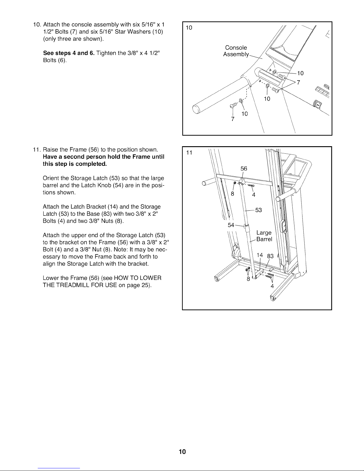
10. Attach the console assembly with six 5/16" x 1
1/2" Bolts (7) and six 5/16" Star Washers (10)
(only three are shown).
See steps 4 and 6. Tighten the 3/8" x 4 1/2"
Bolts (6).
10
Console
Assembly_
0
7
10
7
11. Raise the Frame (56) to the position shown.
Have a second person hold the Frame until
this step is completed.
Orient the Storage Latch (53) so that the large
barrel and the Latch Knob (54) are in the posi-
tions shown.
Attach the Latch Bracket (14) and the Storage
Latch (53) to the Base (83) with two 3/8" x 2"
Bolts (4) and two 3/8" Nuts (8).
Attach the upper end of the Storage Latch (53)
to the bracket on the Frame (56) with a 3/8" x 2"
Bolt (4) and a 3/8" Nut (8). Note: It may be nec-
essary to move the Frame back and forth to
align the Storage Latch with the bracket.
Lower the Frame (56) (see HOW TO LOWER
THE TREADMILL FOR USE on page 25).
11
56
10
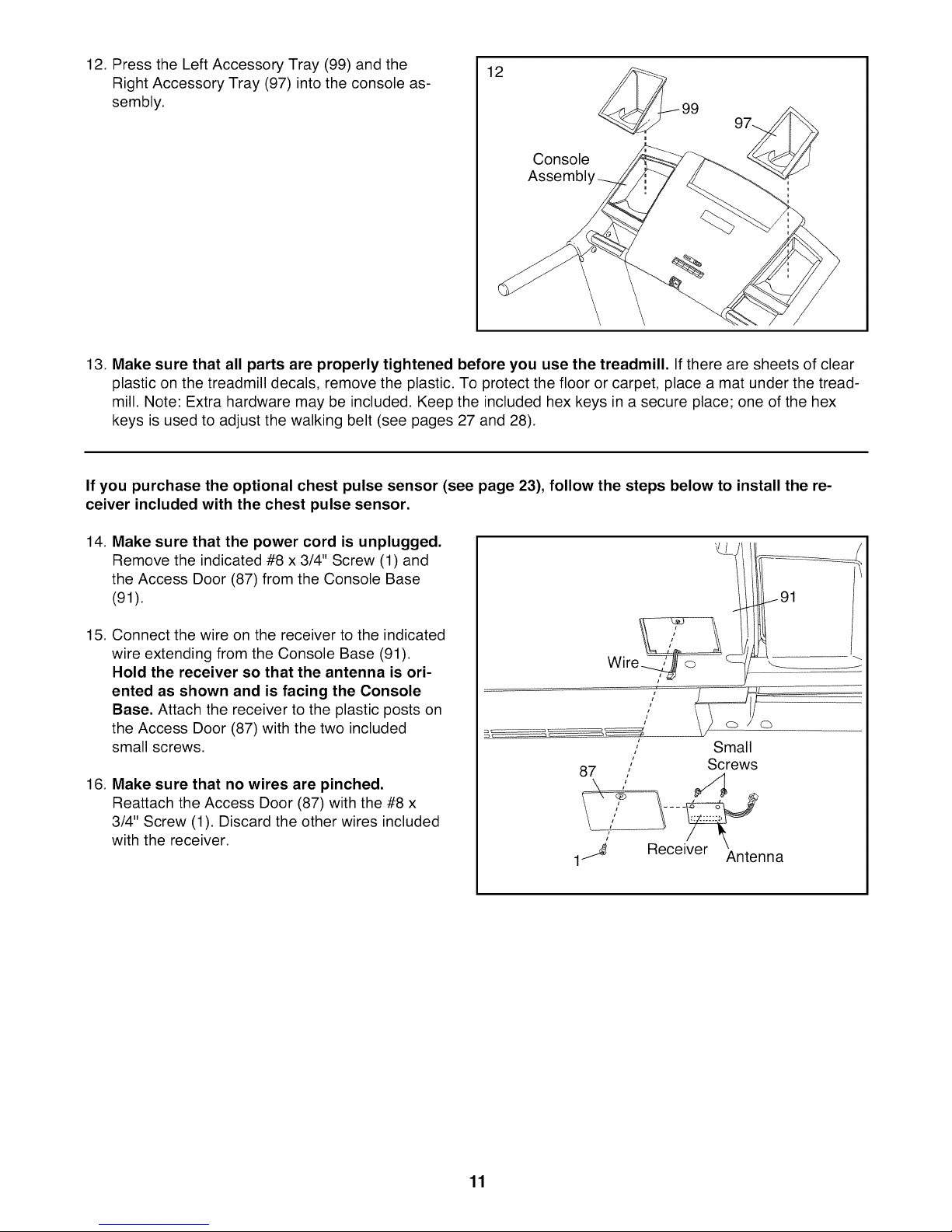
12. Press the Left Accessory Tray (99) and the
12
Right Accessory Tray (97) into the console as-
sembly.
Console
Assembl'
13. Make sure that all parts are properly tightened before you use the treadmill. If there are sheets of clear
plastic on the treadmill decals, remove the plastic. To protect the floor or carpet, place a mat under the tread-
mill. Note: Extra hardware may be included. Keep the included hex keys in a secure place; one of the hex
keys is used to adjust the walking belt (see pages 27 and 28).
If you purchase the optional chest pulse sensor (see page 23), follow the steps below to install the re-
ceiver included with the chest pulse sensor.
14. Make sure that the power cord is unplugged.
Remove the indicated #8 x 3/4" Screw (1) and
the Access Door (87) from the Console Base
(91).
15. Connect the wire on the receiver to the indicated
wire extending from the Console Base (91).
Hold the receiver so that the antenna is ori-
ented as shown and is facing the Console
Base. Attach the receiver to the plastic posts on
the Access Door (87) with the two included
small screws.
16. Make sure that no wires are pinched.
Reattach the Access Door (87) with the #8 x
3/4" Screw (1). Discard the other wires included
with the receiver.
, Small
,,
, Screws
Cb
11
 Loading...