

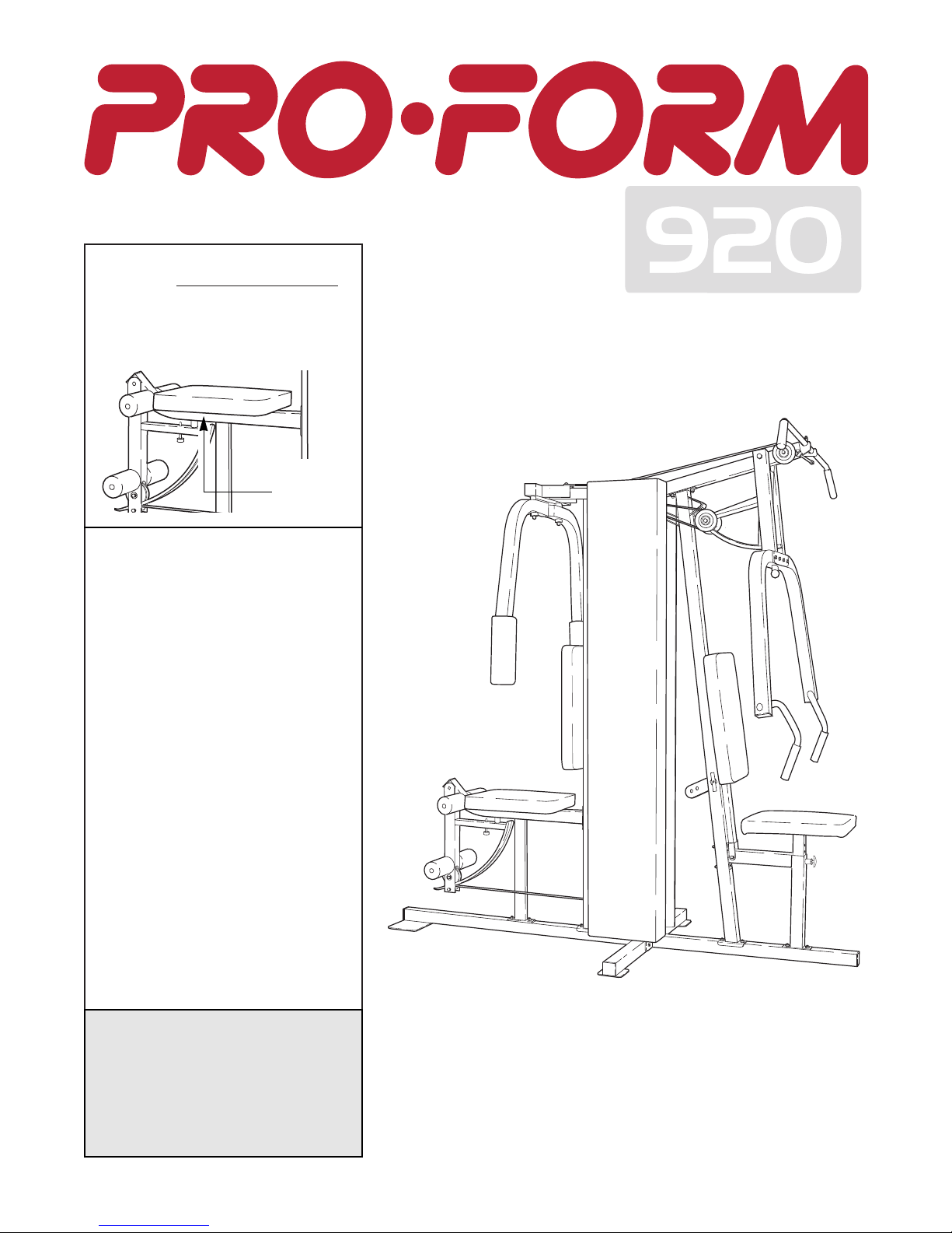
ProForm 920 User Manual
¨
USERÕS MANUAL
Model No. PFSY92080
Serial No.
The serial number is found in the
location shown below. Write the
serial number in the space above.
CAUTION
Read all precautions and instructions in this manual before using
this equipment. Save this manual for future reference.
Serial
Number
Decal
PATENT PENDING
QUESTIONS?
As a manufacturer, we are
committed to providing complete
customer satisfaction. If you
have questions, or if there are
missing or damaged parts, we
will guarantee complete satisfaction through direct assistance
from our factory.
TO AVOID UNNECESSARY
DELAYS, PLEASE CALL DIRECT
TO OUR TOLL-FREE CUSTOMER
HOT LINE. The trained technicians on our customer hot line
will provide immediate assistance, free of charge to you.
CUSTOMER HOT LINE:
1-800-999-3756
Mon.ÐFri., 6 a.m.Ð6 p.m. MST

2
Important Precautions . . . . . . . . . . . . . . . . . . . . . . . . . . . . . . . . . . . . . . . . . . . . . . . . . . . . . . . . . . . . . . . . . . . 2
Before You Begin . . . . . . . . . . . . . . . . . . . . . . . . . . . . . . . . . . . . . . . . . . . . . . . . . . . . . . . . . . . . . . . . . . . . . . 3
Assembly . . . . . . . . . . . . . . . . . . . . . . . . . . . . . . . . . . . . . . . . . . . . . . . . . . . . . . . . . . . . . . . . . . . . . . . . . . . . 4
Cable Diagram . . . . . . . . . . . . . . . . . . . . . . . . . . . . . . . . . . . . . . . . . . . . . . . . . . . . . . . . . . . . . . . . . . . . . . . 19
Adjustment . . . . . . . . . . . . . . . . . . . . . . . . . . . . . . . . . . . . . . . . . . . . . . . . . . . . . . . . . . . . . . . . . . . . . . . . . . 20
Weight Resistance Chart . . . . . . . . . . . . . . . . . . . . . . . . . . . . . . . . . . . . . . . . . . . . . . . . . . . . . . . . . . . . . . . . 22
Trouble-shooting and Maintenance . . . . . . . . . . . . . . . . . . . . . . . . . . . . . . . . . . . . . . . . . . . . . . . . . . . . . . . . 23
Ordering Replacement Parts . . . . . . . . . . . . . . . . . . . . . . . . . . . . . . . . . . . . . . . . . . . . . . . . . . . . . . Back Cover
Limited Warranty . . . . . . . . . . . . . . . . . . . . . . . . . . . . . . . . . . . . . . . . . . . . . . . . . . . . . . . . . . . . . . . Back Cover
Note: A PART LIST/EXPLODED DRAWING and a PART IDENTIFICATION CHART are attached to the center of
this manual. Remove the PART LIST/EXPLODED DRAWING and the PART IDENTIFICATION CHART before
beginning assembly.
WARNING: Before beginning this or any exercise program, consult your physician. This is especially
important for persons over the age of 35 or persons with pre-existing health problems. Read all
instructions before using. ICON assumes no responsibility for personal injury or property damage
sustained by or through the use of this product.
Table of Contents
Important Precautions
1. It is the responsibility of the owner to ensure
that all users of the home gym system are
adequately informed of all precautions.
2. Read all instructions in this manual and in
the accompanying literature before using the
home gym system.
3. If you feel pain or dizziness at any time while
exercising, stop immediately and begin cooling down.
4. Use the home gym system only on a level
surface. Cover the floor or carpet beneath the
home gym system for protection.
5. Inspect and tighten all parts often. Replace
any worn parts immediately.
6. Make sure the cables remain on the pulleys
at all times. If the cables bind while you are
exercising, stop immediately and make sure
the cables are on all of the pulleys.
7. Always stand on a foot plate when performing an exercise that could cause the home
gym system to tip.
8. Keep children under the age of 12 and pets
away from the home gym system at all times.
9. Keep hands and feet away from moving parts.
10. The home gym system is designed to be
used by only one person at a time.
11. Always wear athletic shoes for foot protection when exercising.
12. Never release the press arm, butterfly arms,
leg lever, lat bar, row bar or ankle strap while
weights are raised. The weights will fall with
great force.
13. Always disconnect the lat bar, row bar or
ankle strap from the home gym system when
performing an exercise that does not use
these attachments.
14. The home gym system is intended for home
use only. Do not use the home gym system in
a commercial, rental or institutional setting.
To reduce the risk of serious injury, read the following important
precautions before using the home gym system.
WARNING:
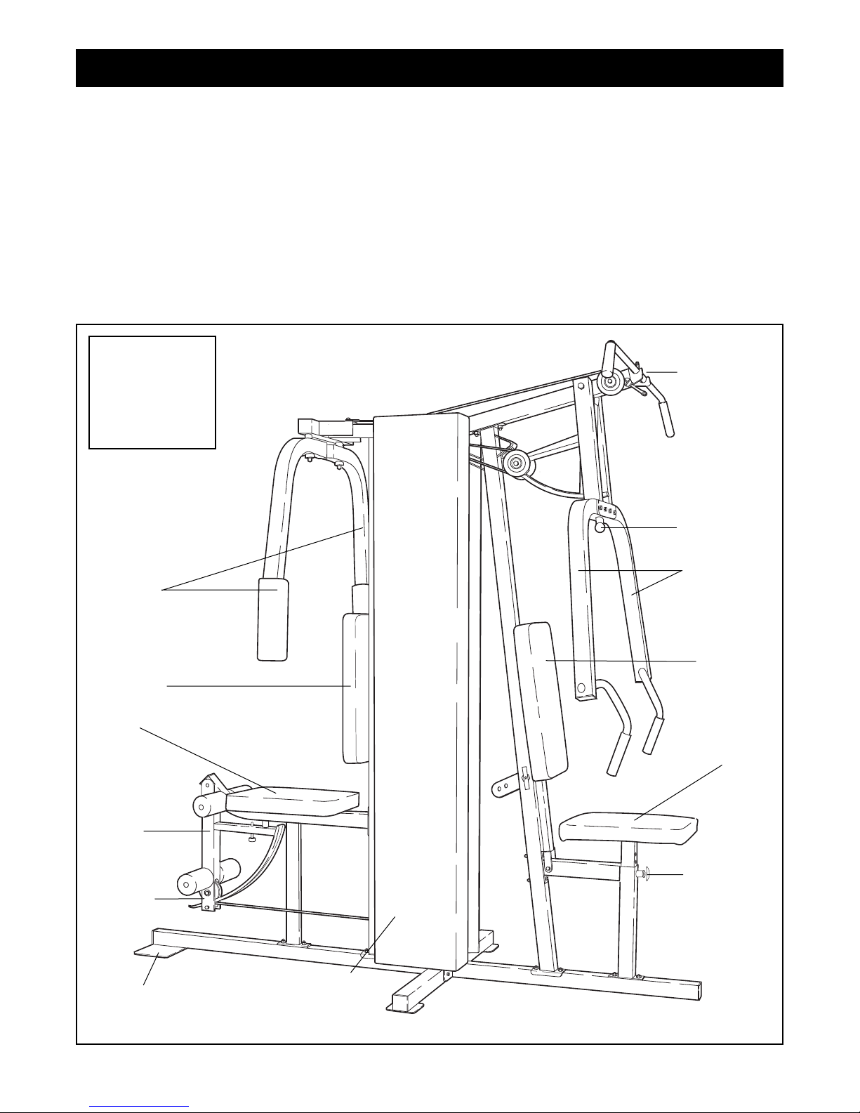
3
ASSEMBLED
DIMENSIONS:
Height: 79 in.
Width: 38 in.
Length: 91 in.
Low Pulley
Station
Foot Plate
Leg
Lever
Butterfly
Arms
Press Arm
Shroud
Covering
Weight Stack
Seat
Backrest
Thank you for selecting the versatile PROFORM¨920
Home Gym System. The PROFORM¨920 offers a
selection of weight stations designed to develop every
major muscle group of the body. Whether your goal is
to tone your body, build dramatic muscle size and
strength or improve your cardiovascular system, the
PROFORM¨920 will help you to achieve the results
you want.
For your benefit, read this manual carefully before
using the PROFORM¨920 Home Gym System. If
you have additional questions, please call our
Customer Service Department toll-free at 1-800-9993756, Monday through Friday, 6 a.m. until 6 p.m.
Mountain Time (excluding holidays). To help us assist
you, please note the product model number and serial
number before calling. The model number is
PFSY92080. The serial number can be found on a
decal attached to the PROFORM¨920 Home Gym
System (see the front cover of this manual).
Please use the drawing below to familiarize yourself with the major parts and how they fit together.
Before You Begin
Backrest
Seat
Locking Pin
Adjustment
Knob
High Pulley
Station
4
Note: This introduction will save you more
time than it takes to read it!
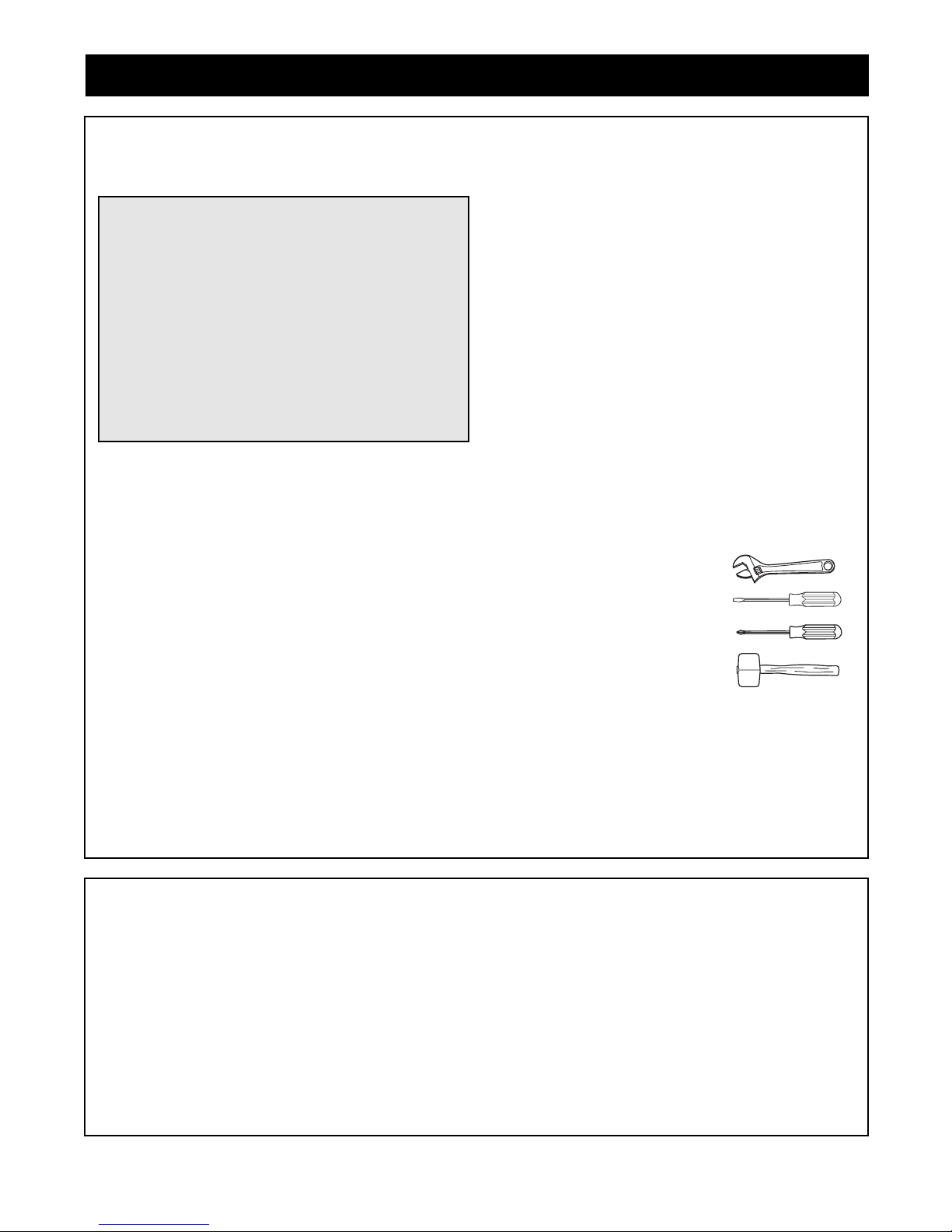
Identifying Parts
To help you identify the small parts used in assembly, we have included a PART IDENTIFICATION
CHART located in the center of this manual. Place
the chart on the floor or work table and use it to
quickly identify different parts as you open the packages for each step.
Note: Some small parts may have been pre-attached
for shipping. If a part is not in the parts bag, check to
see if it has been pre-attached.
Orienting Parts
As you assemble this product, be sure that all parts
are oriented as shown in the drawings.
Tightening of Parts
Tighten all parts as you assemble them, unless
instructed to do otherwise.
Lining Up the Tools
Assembly requires the following tools (not included):
¥ Two (2) adjustable wrenches
¥ One (1) standard screwdriver
¥ One (1) phillips screwdriver
¥ One (1) rubber mallet
¥ Lubricant, such as grease or petroleum jelly,
and soapy water
¥ Tape, such as clear tape or masking tape
Assembly will be more convenient if you have a
socket set, a set of open-end or closed-end wrenches
or a set of ratchet wrenches.
Giving Yourself a Good Start
Before you begin the assembly process itself, take
the time to complete the steps outlined here.
Clearing the Workspace
Clear a workspace that is large enough to hold all
parts and allow you to walk all the way around the
assembled equipment.
Unpacking the Box
To make the assembly process as smooth as possible, we have broken it into separate stages. All parts
used in each stage are found in individual packages
in the shipping box. Place all parts in a cleared area
and remove the packing materials. Do not dispose of
the packing materials until assembly is completed.
Important: Wait until you begin each assembly
stage to open the parts bag labeled for that
assembly stage.
Assembly
Making Things Easier for Yourself
Everything in this manual is designed to ensure
that the assembly of our products can be completed successfully by anyone. However, it is important to recognize that your new equipment is a
sophisticated product with many small parts. The
assembly process will take timeÑpossibly several
hours. Most people find that by setting aside plenty of time, and by deciding to make the task
enjoyable, assembly will go smoothly. You may
want to complete the process over a couple of
evenings.
The Four Stages of the Assembly Process
Frame Assembly
You will begin by assembling the base and the
upright frames that serve as the skeleton of the
equipment. The seats and all moving parts will
later be attached to the frame.
Arm Assembly
Completes the press and butterfly arms that you
operate while you are exercising.
Cable Assembly
Completes the cables and pulleys that connect the
moving arms with each other and with the weights.
This ties the different parts together and makes the
equipment function as a unit.
Seat Assembly
Completes the seats and backrests that support
your body while you are exercising.
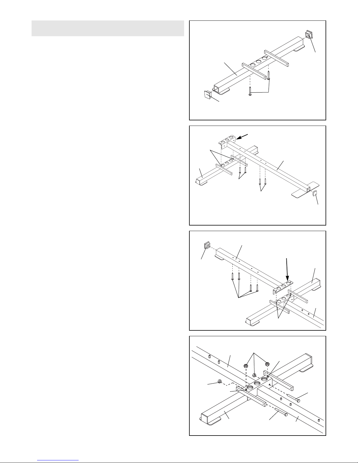
1. Before beginning, make sure that you have read
and understood the information on page 4.
Locate and open the parts bag labeled ÒFRAME
ASSEMBLY.Ó
Press a 2Ó Square Inner Cap (24) into each end of the
Stabilizer (5). Insert two 3/8Ó x 2 3/4Ó Carriage Bolts
(20) up through the holes in the Stabilizer and place it
flat on the floor.
1
2. Press a 2Ó Square Inner Cap (24) into the end of the
Butterfly Base (8).
Insert four 5/16Ó x 2 1/2Ó Carriage Bolts (22) up
through the Butterfly Base (8) and secure the bolt
heads with pieces of tape to prevent them from falling
out.
Place the Butterfly Base (8) on the floor with the
holes in the mounting bracket over the Carriage Bolts
(20) in the Stabilizer (5).
3. Press a 2Ó Square Inner Cap (24) into the end of the
Press Base (4).
Insert four 5/16Ó x 2 1/2Ó Carriage Bolts (22) up
through the holes in the Press Base (4) and secure
the bolt heads with tape. Place the Press Base (4) on
the floor with the holes in the mounting bracket over
the Carriage Bolts (20) in the Stabilizer (5).
Note: The mounting bracket on the Press Base (4)
must be on top of the mounting bracket on the
Butterfly Base (8).
4. Insert two 3/8Ó x 2 3/4Ó Bolts (18) through the holes in
the mounting brackets on the Press Base (4) and
Butterfly Base (8) and through the holes in the
Stabilizer (5).
Tighten four 3/8Ó Nylon Locknuts (50) onto the four
Bolts (18 and 20) in the mounting brackets and
Stabilizer (5).
2
3
4
5
Frame Assembly
24
24
20
5
24
8
22
20
Mounting Bracket
Mounting
Bracket
22
5
22
20
24
5
5
18
8
4
50
50
18
20
20
8
4
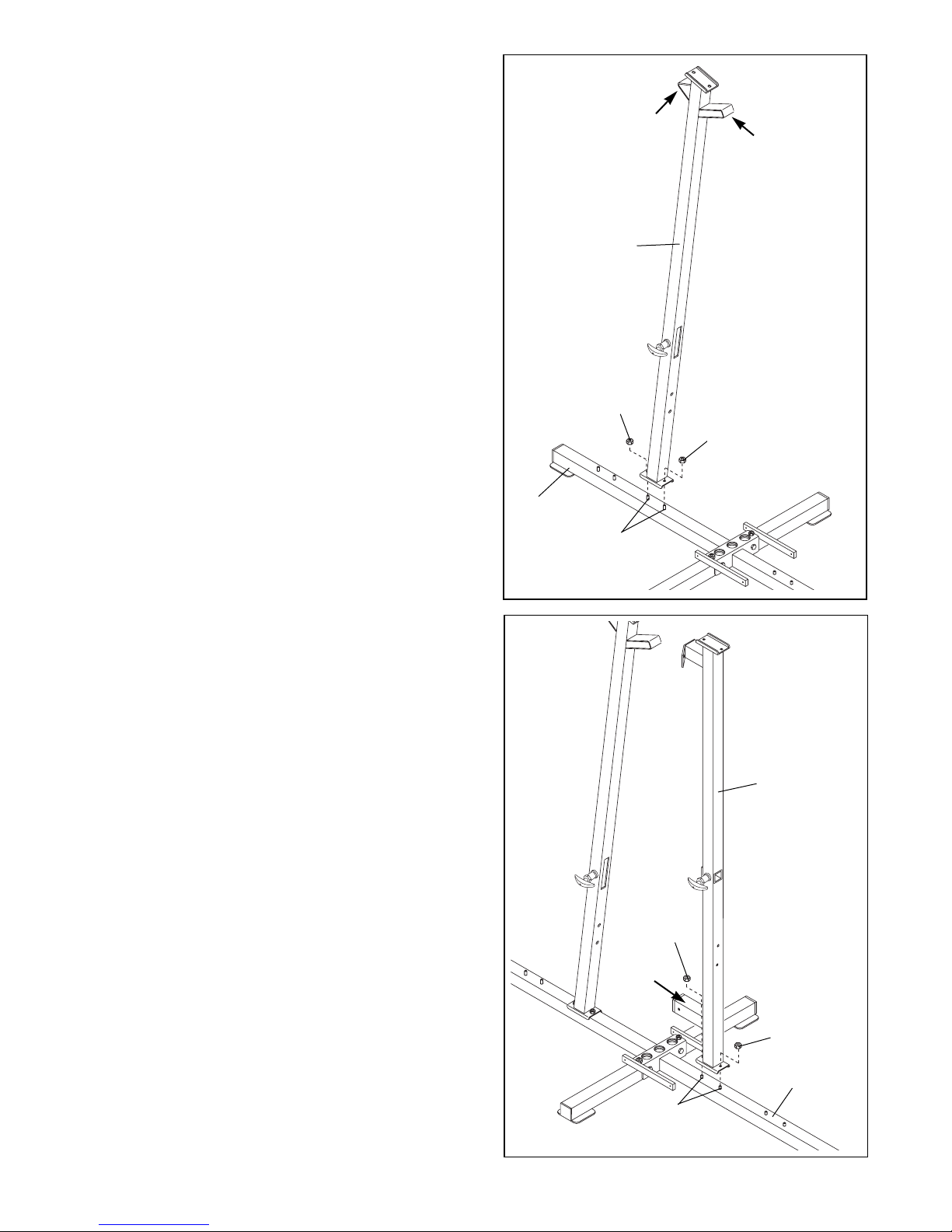
5. Slide the Press Upright (3) onto the indicated 5/16Ó x
2 1/2Ó Carriage Bolts (22) in the Press Base (4).
Tighten a 5/16Ó Nylon Locknut (68) onto each
Carriage Bolt.
Note: The Press Upright (3) must be leaning towards
the center of the unit with the two brackets oriented
as shown.
5
6
6. Slide the Butterfly Upright (2) onto the indicated 5/16Ó
x 2 1/2Ó Carriage Bolts (22) in the Butterfly Base (8).
Hand tighten a 5/16Ó Nylon Locknut (68) onto each
Carriage Bolt.
Do not tighten the Nylon Locknuts yet.
Note: The Butterfly Upright (2) must be oriented as
shown with the bracket pointed towards the center of
the unit.
6
68
68
3
Bracket
Bracket
Bracket
4
22
2
8
22
68
68
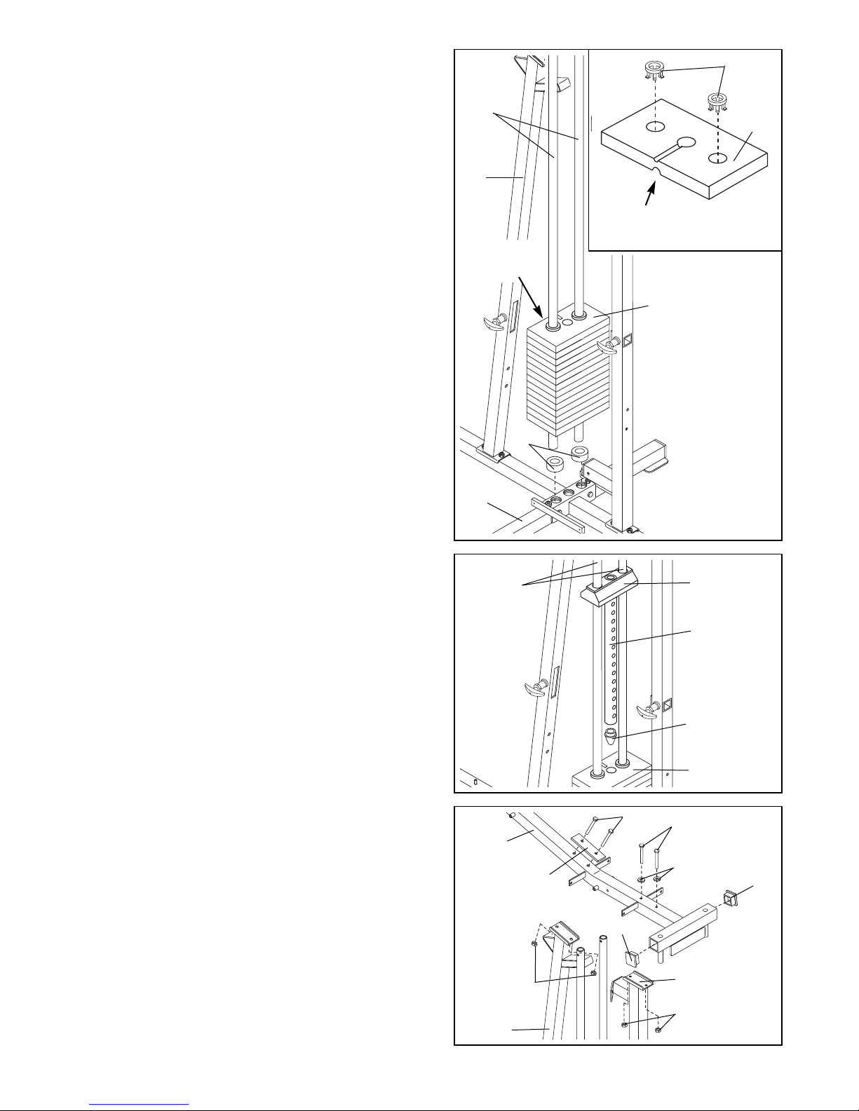
7. Position two Weight Bumpers (19) over the indicated
holes in the Stabilizer (5).
Insert both Weight Guides (23) through the Weight
Bumpers (19) and the holes in the Stabilizer (5).
See the inset drawing. Press two Round Weight
Inserts (76) into the indicated holes in each Weight
(26). Make sure the large pin groove is pointed
downward, as shown.
Slide all of the included Weights (26) onto the two
Weight Guides (23). Make sure the Weights are ori-
ented correctly. The holes must be turned
towards the Press Upright (3), as shown.
7
7
8. Press the Weight Tube Bumper (64) into the end of
the Weight Tube (77).
Lubricate the insides of the holes in the Top Weight
(16).
Slide the Weight Tube (77) with the pre-attached Top
Weight (16) onto the Weight Guides (23). The Weight
Tube will slide into the hole in the center of the
Weights (26).
8
9. Press a 2Ó Square Inner Cap (24) into each end of
the crossbar on the Top Frame (1).
Place the Top Frame (1) on top of the two Uprights (2)
and (3) in the direction shown. Align the holes in the
Top Frame with the holes in the brackets on the
Uprights.
Insert two 5/16Ó x 2 1/2Ó Bolts (45) with two 5/16Ó Flat
Washers (53) through the holes in the Top Frame (1)
and the bracket on the Butterfly Upright (2). Hand
tighten a 5/16Ó Nylon Locknut (68) unto each Bolt. Do
not tighten the Nylon Locknuts yet.
Insert two 5/16Ó x 2 3/4Ó Bolts (60) through the holes
in the Support Plate (52), through the Top Frame (1)
and the bracket on the Press Upright (3). Hand tighten a 5/16Ó Nylon Locknut (68) unto each Bolt. Do not
tighten the Nylon Locknuts yet.
9
5
23
23
3
26
19
16
77
26
64
60
45
53
24
24
2
68
3
52
1
68
76
26
Large Pin
Groove
Holes on
this side
8
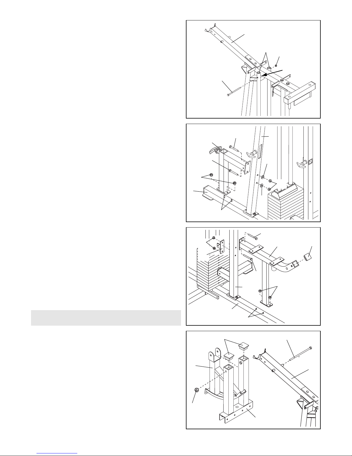
13. Press Arm AssemblyÑLocate and open the parts
bag labeled ÒARM ASSEMBLY.Ó
Press a 2Ó Square Inner Cap (24) into the top of each
arm on the Press Frame (12). Lubricate the 1/2Ó x
9 1/2Ó Bolt (59). Slide the Cable Frame (57) in
between the arms of the Press Frame (12). Slide both
the Cable Frame and the Press Frame onto the Top
Frame (1) and align the holes in all three parts. Note:
This may be a tight fit. Attach the Cable Frame and
the Press Frame to the Top Frame with the 1/2Ó x
9 1/2Ó Bolt and a 1/2Ó Nylon Locknut (51). Do not
overtighten the Nylon Locknut; it must be easy to
pivot the Press Frame and Cable Frame.
13
Arm Assembly
12. Press a 2Ó Square Inner Cap (24) into the Butterfly
Seat Frame (11). Slide the Butterfly Seat Frame onto
the 5/16Ó x 2 1/2Ó Carriage Bolts (22) in the Butterfly
Base (8). Hand tighten a 5/16Ó Nylon Locknut (68)
onto each Carriage Bolt.
Insert two 5/16Ó x 2 3/4Ó Bolts (60) through the bracket on the Butterfly Seat Frame (11) and through the
holes in the Butterfly Upright (2). Orient the Support
Bracket (27) as shown in the drawing (the horizontal
arm of the bracket must be on the side facing away
from you in the drawing) and slide it onto the Bolts.
Hand tighten a 5/16Ó Nylon Locknut (68) onto each
Bolt. Tighten all Nylon Locknuts used in steps 6
through 12.
12
11. Slide the Press Seat Upright (37) onto the 5/16Ó x
2 1/2Ó Carriage Bolts (22) in the Press Base (4). Hand
tighten a 5/16Ó Nylon Locknut (68) onto each Carriage
Bolt. Do not tighten the Nylon Locknuts yet.
Insert two 5/16Ó x 2 1/2Ó Carriage Bolts (22) through
the bracket on the Press Seat Upright (37) and
through the holes in the Press Upright (3). Slide a
5/16Ó Flat Washer (53) onto each Bolt. Hand tighten a
5/16Ó Nylon Locknut (68) onto each Bolt. Do not
tighten the Nylon Locknuts yet.
11
10. Attach the upper ends of the Weight Guides (23) to
the welded bushing underneath the Top Frame (1)
with a 5/16Ó x 6 1/2Ó Bolt (89) and a 5/16Ó Nylon
Locknut (68). Tighten the Nylon Locknut fully.
10
3
22
68
22
11
68
60
24
60
2
59 Lubricate
51
12
24
22
68
Welded
Bushing
23
89
1
53
53
22
37
4
1
57
8
68
27
68
9
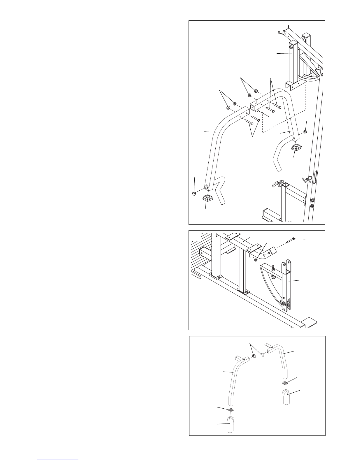
16. Butterfly Arm Assembly
Press a 2Ó Square Inner Cap (24) into both ends of
each Butterfly Arm (80 and 81).
Wet the lower end of each Arm with soapy water.
Slide a Butterfly Foam Pad (82) onto the lower end of
each Arm.
16
14. Press a 2Ó Square Inner Cap (24) into the lower end
of each Press Arm (46 and 47).
Press a 1Ó Round Inner Cap (88) into the side of each
Press Arm.
Identify the Right Press Arm (47). It has a Locking Pin
(98) mounted on the upper end.
Attach the Right Press Arm (47) to the Press Frame
(12) with two 3/8Ó x 2 3/4Ó Bolts (18) and two 3/8Ó
Nylon Locknuts (50).
Attach the Left Press Arm (46) in the same manner.
Note: The terms right and left are used in reference to
a person sitting on the Seat facing away from the
weight stack.
Make sure both Press Arms are oriented as
shown. Tighten the Nylon Locknuts fully.
14
50
12
50
18
46
47
88
88
24
24
98
18
80
24
82
81
24
82
24
15. Leg Lever Assembly
Attach the Leg Lever (29) to the Butterfly Seat Frame
(11) with a 3/8Ó x 2 3/4Ó Bolt (18) and a 3/8Ó Nylon
Jamnut (21).
15
11
29
18
21
 Loading...