

Proform 831298400 Owner’s Manual
Model No. 831.298400
Serial No.
Find the serial number"inthe location
shown below. Write the serial number
inthe space above for reference.
HELPLINE!
1-800-736-6879
USER'S MANUAL
SEARS, ROEBUCK AND CO., HOFFMAN ESTATES, IL 60179

TABLE OFCONTENTS
IMPORTANT PRECAUTIONS ................................................................ .2
BEFORE YOU BEGIN ....................................................................... 4
ASSEMBLY ............................................................................... 5
OPERATION AND ADJUSTMENT ............................................................. 7
HOW TO FOLD AND MOVE THE TREADMILL .................................................. 11
MAINTENANCE AND TROUBLE-SHOOTING ....... . ........................................... 12
CONDITIONING GUIDELINES ............................................................... 14
PART LIST ............................................................................... 15
ORDERING REPLACEMENT PARTS .................................................. Back Cover
FULL 90-DAY WARRANTY ........................................................... Back Cover
Note: An EXPLODED DRAWING is attached in the center of this manual.
IMPORTANT PRECAUTIONS
2_.
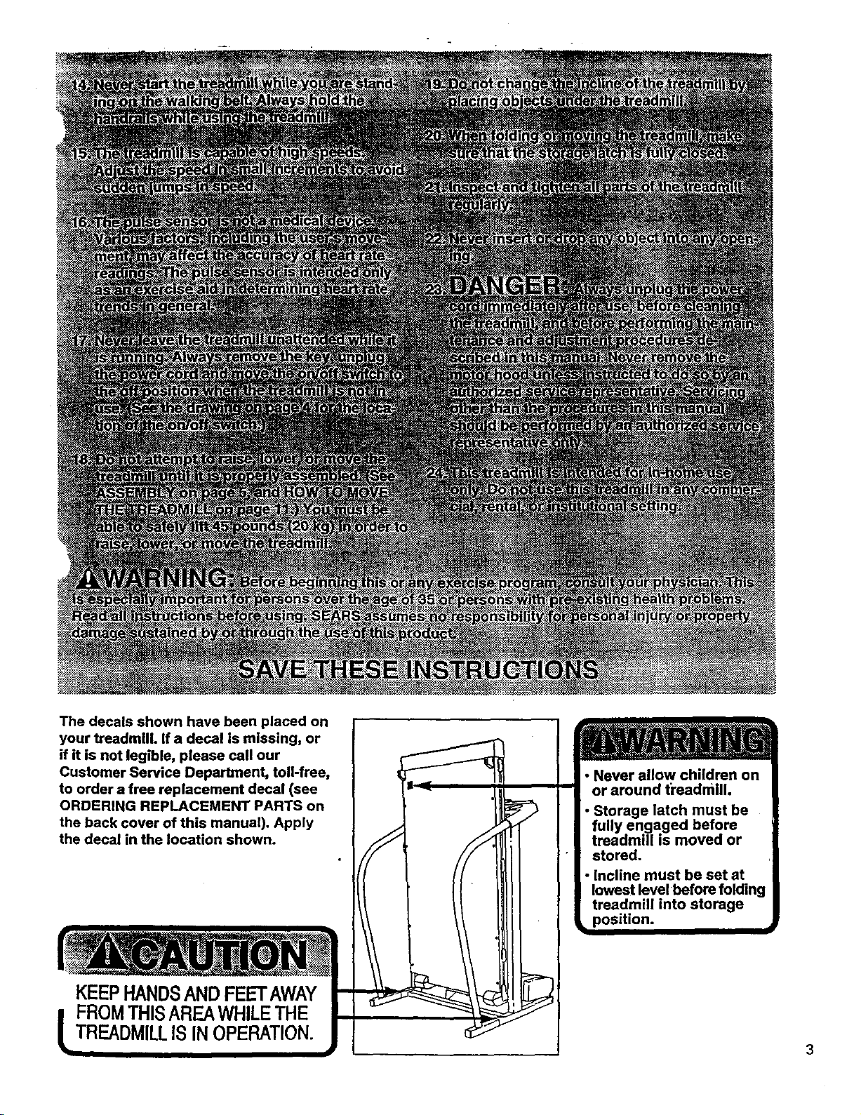
The decals shown have been placed on
your treadmill. If a decal is missing, or
if it is not legible, please call our
Customer Service Department, toll-free,
to order a free replacement decal (see
ORDERING REPLACEMENT PARTS on
the back cover of this manual). Apply
the decal in the location shown.
KEEPHANDSAND FEETAWAY
FROMTHISAREAWHILETHE
TREADMILLIS IN OPERATION.
• Never allow children on
or around ti'eadmill.
Storage latch must be
ed before
moved or
stored.
• Incline must be set at
lowest level before folding
treadmill into storage
position.
3
BEFORE YOU BEGIN
Thank you for selecting the new PROFORM ° 535LE
treadmill. The 535LE treadmill combines advanced
technology with innovative design to letyou enjoy an
excellent form of cardiovascular exercise in the conve-
nience and privacy of your home. And when you're not
exercising, the unique 535LE _ be folded up, requir-
ing less than half the floor space of other treadmills.
For your benefitt read this manuel carefully before
using the treadmill. If you have additional questions,
please call our toll-free HELPLINE at 1-800-736-6879,
Monday through Saturday, 7 a.m. until 7 p.m. Central
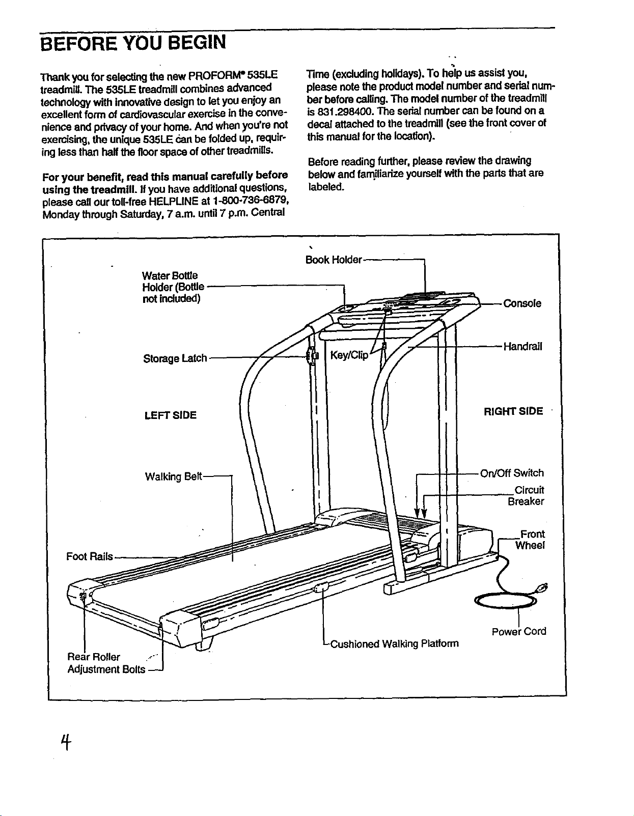
Water Bottle
Holder (Bottle
no_included)
Storage Latch
Time (exoluding holidays). To help us assist you,
please note the product model number and serial num-
ber before calling. The modal number of the treadmill
is 831.298400. The sedat number can be found on a
decal attached to the treadmill (see the front cover of
this manual for the location).
Before reading further, please review the drawing
below and fam.iliadzeyourself with the parts that are
Irabeled.
Handrail
F_tR_is
r Roller .-"
Adjustment Bolts
LEFT SIDE
Walking
RIGHT SIDE "
.Circu_
Breaker
Front
Wheel
r Cord
Platform
ASSEMBLY
_.ssembly requires two people. Set the treadmill in a cleared area and remove all packing materials. Do not
Jispose
and your own phillips screwdriver (]_m_ =-",=- .
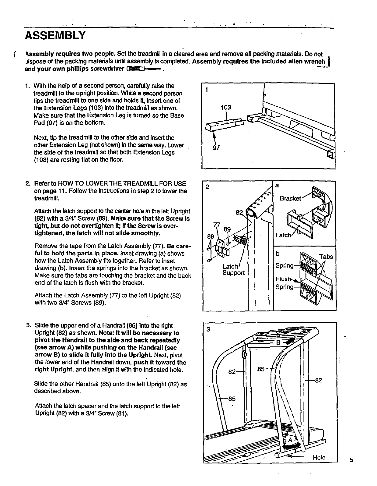
1. With the help of a second person, carefully raise the
of the packing matedels until assembly is completed. Assembly requires the included allen wrenc_
treadmill to the upright position. While a second person
tips the treadmill to one side and holds it, Insertone of
the Extension Legs (103) into the treadmill as shown.
Make sure that the Extension Leg is tumed so the Base
Pad (97) is on the bottom.
Next, tip the treadmill to the other side and insertthe
other Extension Leg (not shown) inthe same way. Lower
the side of the treadmill so that both Extension Legs
(103) are resting flat on the floor.
2. Refer to HOW TO LOWER THE TREADMILL FOR USE
on page 11. Follow the instructions in step 2 to lower the
treadmill.
Attach the latch supportto the canter hole inthe left Upright
(82) with a 3/4" Screw (89). Make sure that the Screw is
tight, but do not overtighten it; if the Screw is over-
tightened, the latch will not slide smoothly.
Remove the tape from the Latch Assembly (77). Be care-
ful to hold the parts in place. Inset drawing (a) shows
how the Latch Assembly fits together. Refer to inset
drawing (b). Insert the springs into the bracket as shown.
Make sure the tabs are touching the bracket and the back
end of the latch is flush with the bracket.
Attach the Latch Assembly (77) to the left Upright (82)
with two 3/4" Screws (89).
3. Slide the upper end of a Handrail (85) into the right
Upright (82) as shown. Note: It will be necessary to
pivot the Handrail to the side and back repeatedly
(see arrow A) while pushing on the Handrail (see
arrow B) to slide it fully into the Upright. Next, pivot
the lower end of the Handrail down, push it toward the
right Upright, and then align it with the indicated hole.
d
Slide the other Handrail (85) onto the left Upright (82) as
described above.
2
82
Support
3
a
Bracket_
Latch_
Spring--
Flush.._.
b _ Tab_
Spdng--
Attach the latch spacer and the latch support to the left
Upright (82) with a 3/4" Screw (81).
Hole 5
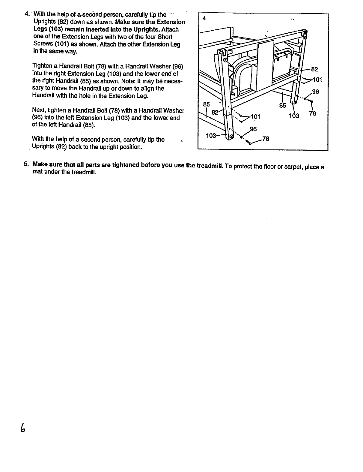
4: With the help of asecortd person, carefully tip the
Uprights (82) down as shown. Make sure the Extension
Legs (103) remain inserted into the Uprights. A_ach
one of the Extension Legs with two of the four Short
Screws (101) as shown. Attach the other Extension Leg
in the same way.
4
Tighten a Handrail Bolt (78) with a Handrail Washer (96)
intothe right Extension Leg (103) and the lower end of
the right Handrail (85) as shown. Note: It may be neces-
sary to move the Handrail up or down to align the
Handrail with the hole in the Extension Leg.
Next, tighten a Handrail Bolt (78) with a Handrail Washer
(96) into the left Extension Leg (103) and the lower end
of the left Handrail (85).
--lO 3 78
82
101
'°
.__'-_l'-L / 98
With the help of a second person, carefully tip the
• Uprights (82) back to the upright position.
5. Make sure that all parts are tightened before you use the treadmill. To protect the floor or carpet, place a
mat under the treadmill.
lO3--.--_'-_, 8
 Loading...