

Proform 831297772 Owner’s Manual
PRO.r-ORM
Model No. 831.297772
Serial No.
Rnd the serial number in the location
shown below. Write the serial number
in the space above for reference.
_____111 I Sedal Number
it F
EQUIPMENT
ionlilli|o|_12
H ELPLINI=" !
1-800-736-6879
USER'S MANUAL
SEARS, ROEBUCK AND CO., HOFFMAN ESTATES, IL 60179

TABLE OF CONTENTS
IMPORTANT PRECAUTIONS ................................................................. 2
BEFORE YOU BEGIN ...................................................................... .4
ASSEMBLY .......................................................• ,.......... .. • ..... ... • 5
OPERATION'AND'A'D'3USTMENT ..... "-.:= .'--.-_._-...-; ....... ................................... .7
HOWTO FOLD AND MOVE THE TREADMILL .................................................. 11
TROUBLE-SHOOTING ..................................................................... 12
CONDITIONING GUIDELINES ............................................................... 14
PART LIST ............................................................................... 15
ORDERING REPLACEMENT PARTS .................................................. Back Cover
FULL 90-DAY WARRANTY .......................................... ...... .. • , .. .,. .o Back Cover
Note: An EXPLODED DRAWING is attached in the center of this manual.
IMPORTANT PRECAUTIONS
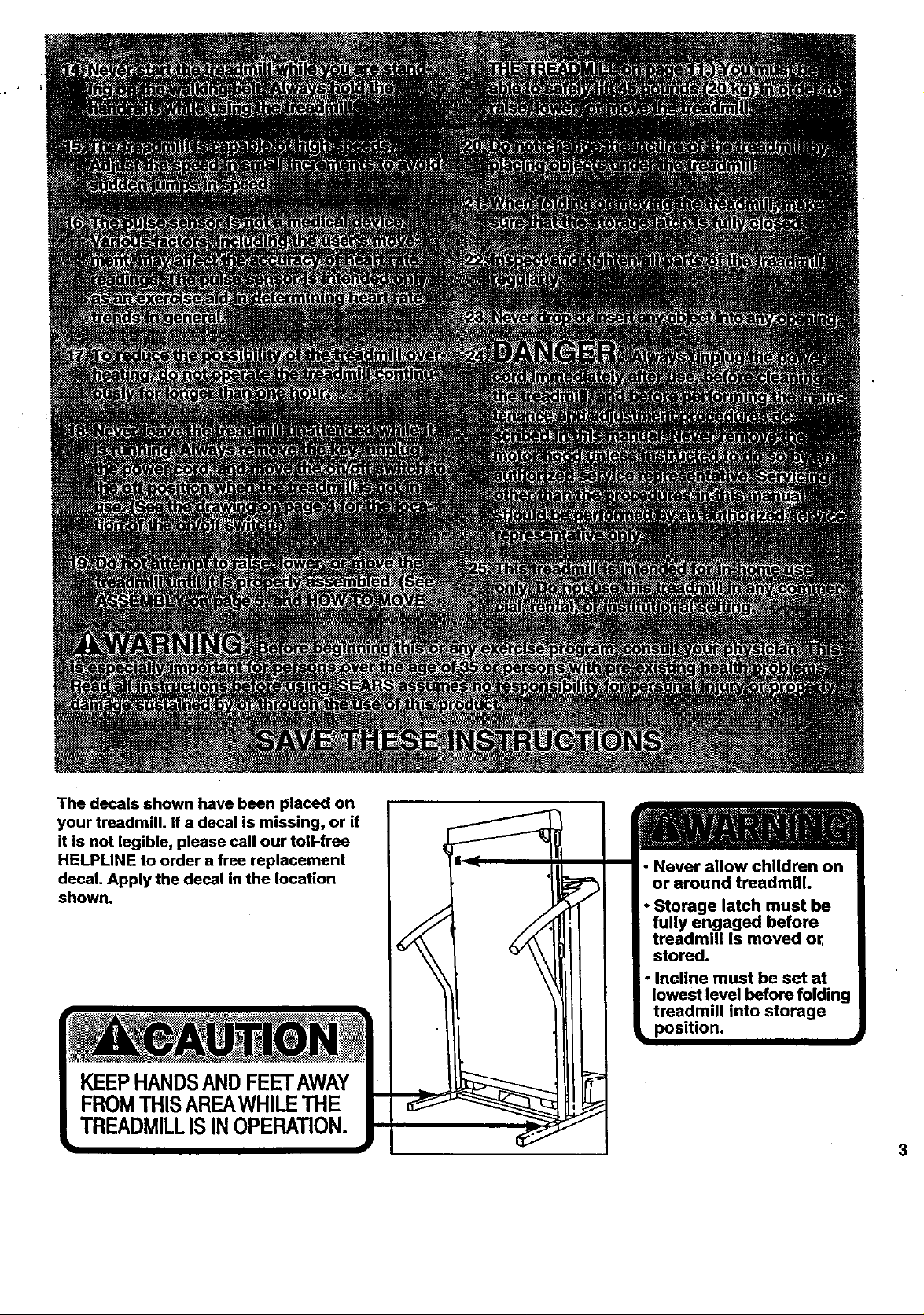
The decals shown have been placed on
your treadmill. If a decal is missing, or if
it is not legible, please call our toU-free
HELPLINE to order a free replacement
decal. Apply the decal in the location
shown.
KEEPHANDSANDFEETAWAY
FROMTHISAREAWHILETHE
TREADMILLISINOPERATION.
• Never allow children on
or around treadmill.
• Storage latch must be
fully engaged before
treadmill is moved or
stored,
• Incline must be set at
lowest level before folding
treadmill into storage
• position.
3
BEFORE YOU BEGIN
Thank you for selecting the new PROFORIVP 595LE Monday through Saturday, 7 a.m. until 7 p.m. Central
treadndlL The 595LE treadmill combines advanced Time (excluding holidays). To help us assist you,
technology with Innovetive design to let you enjoy an please note the product model number and sedal num-
. excellent form'-of__r exercise In the-esnve-. - -ber before calling. The model number of the treadmill
nlence and privacy of your home. And when you're net Is 831,297772. The serial number can be found on a
exerdslng, the unique 595LE can be folded up, requir- decal 8ttached to the treadmill (see the front cover of
ing less than half the floor space of other treadmills, thIs manual for the location).
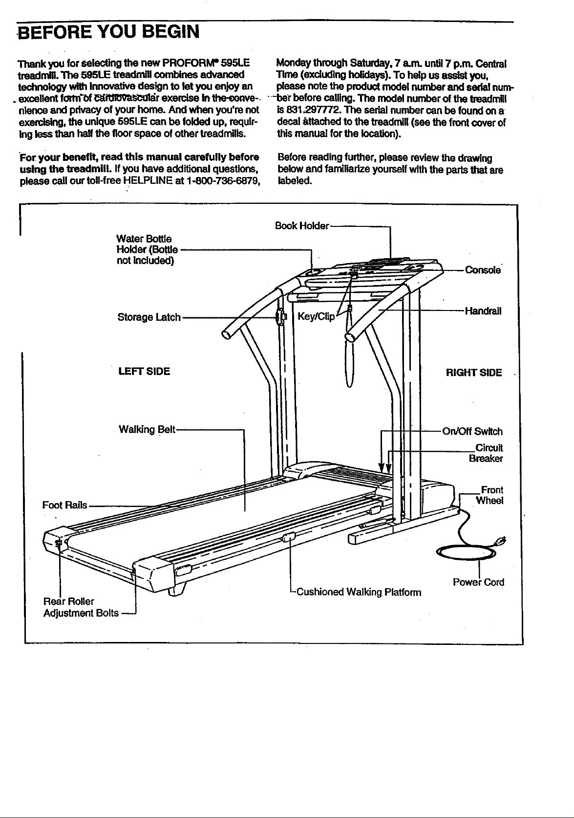
For your benefit, read this manual carefully before Before reading further, please review the drawing
using the treadmill. If you have additional questions, below and familiadze yourself withthe pads that am
please call our toll-free HELPLINE at 1-800-736-6879, labeled.
I
Foot Rails
Water Bottle
Holder (Bottle
not Included)
Storage Latch.
• LEFT SIDE
Walking Belt.
Book Holder
\ \
Handrail
\
RIGHT SIDE
Circuit
Breaker
Wheel
r Roller
Adjustment Bolts
'Cord
Platform
i
ASSEMBLY
Assembly requires tw_ people. Set the treadmill in a cleared area and remove all packing rnatedals. Do not .
dispose of the packing materials until assembly is completed. Assembly requires the Included ellen wrenc.._
and your own phillips screwdriver (_:_-==-,---, adjustable wrench _ and scissors
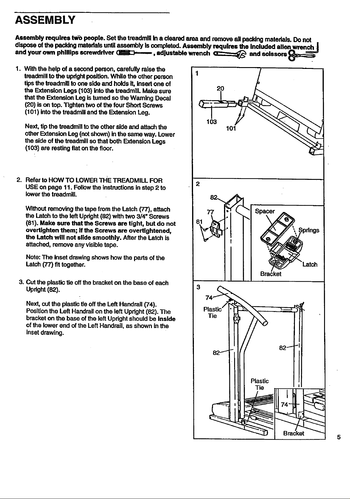
1. With the help of a second person, carefully raise the
treadmill to the updght position. While the other person
tips the treadmill to one side and holds It, Insert one of
the Extension Legs (103) into the tmadmllL Make sure
that the Extension Leg Istumed so the Waming Decal
(20) is on top. Tighten two of the four Short Screws
(101) into the treadmill and the Extension Leg.
Next, tip the treadmill to the other side and attach the
other Extension Leg (not shown) in the same way. Lower
the side of the treadmill so that both Extension Legs
(103) are resting fiat on the floor.
2. Refer to HOWTO LOWER THE TREADMILL FOR
USE on page 11. Follow the instructions in step 2 to
lower the treadmill
Without removing the tape from the Latch (77), attach
the Latch to the left Upright (82) with two 3/4" Screws
(81). Make sure that the Screws ere tight, but do not
overtlghten them; ff the Screws are overtightened,
the Latch will not slide smoothly. After the Latch is
attached, remove any visible tape.
1
20
103
101
Note:The Insetdrawingshowshow the partsof the
Latch (77) f'dtogether.
3. Cut the plastic tie off the bracket on the base of each
Upright (82).
Next, cut the plastic tie off the Left Handrail (74).
Position the Left Handrail on the left Updght (82). The
bracket on the base of the left Upright should be Inside
of the lower end of the Left Handrail, as shown in the
inset drawing.
5
 Loading...