

Page 1
Model No. 831.297763
Serial No.
The serial number is found in the location
shown below. Write the serial number in
the space above for future reference.
Serial
Number
Decal
CAUTION
Read all precautions and instructions in this manual before using
this equipment. Save this manual
for future reference.
USER'S MANUAL
SEARS, ROEBUCK AND CO., HOFFMAN ESTATES, IL 60179
Page 2

TABLE OF CONTENTS
FULL 90 DAY WARRANTY . . . . . . . . . . . . . . . . . . . . . . . . . . . . . . . . . . . . . . . . . . . . . . . . . . . . . . . . . . . . . . . . . . .2
IMPORTANT PRECAUTIONS . . . . . . . . . . . . . . . . . . . . . . . . . . . . . . . . . . . . . . . . . . . . . . . . . . . . . . . . . . . . . . . . .3
BEFORE YOU BEGIN . . . . . . . . . . . . . . . . . . . . . . . . . . . . . . . . . . . . . . . . . . . . . . . . . . . . . . . . . . . . . . . . . . . . . . .5
ASSEMBLY . . . . . . . . . . . . . . . . . . . . . . . . . . . . . . . . . . . . . . . . . . . . . . . . . . . . . . . . . . . . . . . . . . . . . . . . . . . . . . .6
HOW TO USE THE PULSE SENSOR . . . . . . . . . . . . . . . . . . . . . . . . . . . . . . . . . . . . . . . . . . . . . . . . . . . . . . . . . . .8
OPERATION AND ADJUSTMENT . . . . . . . . . . . . . . . . . . . . . . . . . . . . . . . . . . . . . . . . . . . . . . . . . . . . . . . . . . . . .9
HOW TO USE THE MANUAL MODE . . . . . . . . . . . . . . . . . . . . . . . . . . . . . . . . . . . . . . . . . . . . . . . . . . . . . . . .11
HOW TO USE THE WEIGHT LOSS PROGRAMS AND THE INTERVAL PROGRAMS . . . . . . . . . . . . . . . . .13
HOW TO USE THE FAT BURN AND AEROBIC PROGRAM . . . . . . . . . . . . . . . . . . . . . . . . . . . . . . . . . . . . .15
HOW TO USE THE FITNESS TEST PROGRAM . . . . . . . . . . . . . . . . . . . . . . . . . . . . . . . . . . . . . . . . . . . . . . .16
HOW TO FOLD AND MOVE THE TREADMILL . . . . . . . . . . . . . . . . . . . . . . . . . . . . . . . . . . . . . . . . . . . . . . . . . .18
TROUBLE-SHOOTING . . . . . . . . . . . . . . . . . . . . . . . . . . . . . . . . . . . . . . . . . . . . . . . . . . . . . . . . . . . . . . . . . . . . . 20
CONDITIONING GUIDELINES . . . . . . . . . . . . . . . . . . . . . . . . . . . . . . . . . . . . . . . . . . . . . . . . . . . . . . . . . . . . . . . 22
ORDERING REPLACEMENT PARTS . . . . . . . . . . . . . . . . . . . . . . . . . . . . . . . . . . . . . . . . . . . . . . . . . .Back Cover
Note: An EXPLODED DRAWING and a PART LIST are attached to the center of this manual. Please save them
for future reference.
FULL 90 DAY WARRANTY
For 90 days from the date of purchase, if failure occurs due to defect in material or workmanship in this
SEARS TREADMILL EXERCISER, contact the nearest SEARS Service Center throughout the United
States and SEARS will repair or replace the TREADMILL EXERCISER, free of charge.
This warranty does not apply when the
poses.
This warranty gives you specific legal rights, and you may also have other rights which vary from state
to state.
SEARS, ROEBUCK AND CO., DEPT. 817WA, HOFFMAN ESTATES, IL 60179
2
TREADMILL EXERCISER is used commercially or for rental pur-
Page 3

IMPORTANT PRECAUTIONS
WARNING: To reduce the risk of burns, fire, electric shock, or injury to persons, read the
following important precautions and information before operating the treadmill.
1. It is the responsibility of the owner to ensure
that all users of this treadmill are adequately
informed of all warnings and precautions.
2. Use the treadmill only as described in this
manual.
3. Place the treadmill on a level surface, with 8
feet of clearance behind it. Do not place the
treadmill on any surface that blocks air openings. To protect the floor or carpet from damage, place a mat under the treadmill.
4. Keep the treadmill indoors, away from moisture and dust. Do not put the treadmill in a
garage or covered patio, or near water.
5. Do not operate the treadmill where aerosol
products are used or where oxygen is being
administered.
6. Keep children and pets away from the treadmill at all times.
7. The treadmill should be used only by persons
weighing 250 pounds or less.
8. Never allow more than one person on the
treadmill at a time.
9. Wear appropriate exercise clothing when
using the treadmill. Do not wear loose clothing that could become caught in the treadmill.
Athletic support clothes are recommended for
both men and women.
Always wear athletic
shoes. Never use the treadmill with bare feet,
wearing only stockings, or in sandals.
10. When connecting the power cord (see HOW
TO PLUG IN THE POWER CORD on page 9),
plug the power cord into a surge protector
(not included) and plug the surge protector
into a grounded circuit capable of carrying 15
or more amps. No other appliance should be
on the same circuit.
11. Use only a UL-listed surge protector, rated at
15 amps, with a 14-gauge cord of five feet or
less in length. Do not use an extension cord.
12. Keep the power cord and the surge protector
away from heated surfaces.
13. Never move the walking belt while the power
is turned off. Do not operate the treadmill if
the power cord or plug is damaged, or if the
treadmill is not working properly. (See BEFORE YOU BEGIN on page 5 if the treadmill is
not working properly.)
14. Never start the treadmill while you are standing on the walking belt. Always hold the
handrails while using the treadmill.
15. The treadmill is capable of high speeds.
Adjust the speed in small increments to avoid
sudden jumps in speed.
16. To reduce the possibility of the treadmill overheating, do not operate the treadmill continuously for longer than one hour.
17. The pulse sensor is not a medical device.
Various factors, including the user's movement, may affect the accuracy of heart rate
readings. The pulse sensor is intended only
as an exercise aid in determining heart rate
trends in general.
18. Never leave the treadmill unattended while it
is running. Always remove the key and move
the on/off switch to the “off” position when
the treadmill is not in use. (See the drawing on
page 5 for the location of the on/off switch.)
Do not attempt to raise, lower, or move the
19.
treadmill until it is properly assembled. (See
ASSEMBLY on page 6, and HOW TO MOVE
THE TREADMILL on page 19.) You must be
able to safely lift 45 pounds (20 kg) to raise,
lower, or move the treadmill.
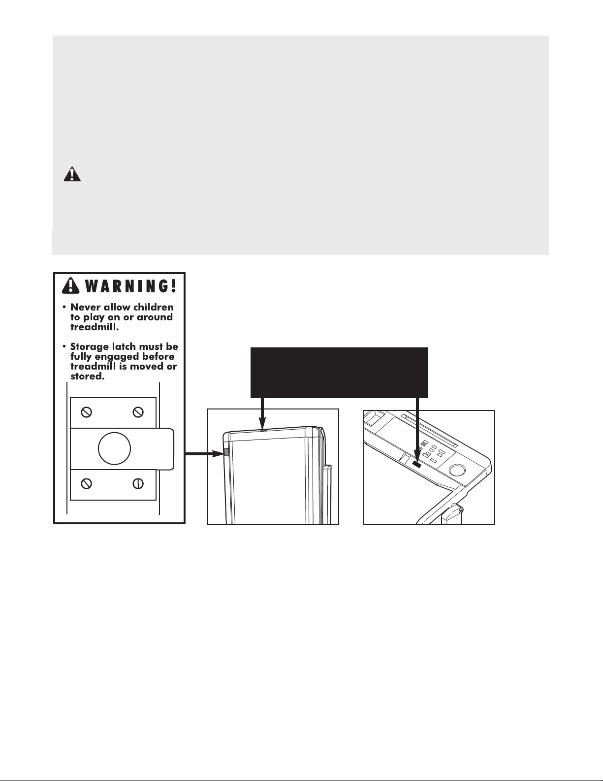
20. When folding or moving the treadmill, make
sure that the storage latch is fully closed.
21.
During the last ten seconds of a preset program, the treadmill will automatically adjust to
the lowest incline level. Keep your feet and objects from beneath the treadmill.
3
Page 4
IMPORTANT: Incline must be at
lowest level before
folding treadmill into
storage position.
22. Inspect and tighten all parts of the treadmill
every three months.
3. Never insert any object into any opening.
2
do so by an authorized service representative. Servicing other than the procedures in
this manual should be performed by an au-
horized service representative only.
t
24. Always unplug the power cord before performing the maintenance and adjustment
procedures described in this manual. Never
emove the motor hood unless instructed to
r
25. This treadmill is intended for in-home use
only. Do not use this treadmill in any commercial, rental, or institutional setting.
WARNING: Before beginning this or any exercise program, consult your physician. This
is especially important for persons over the age of 35 or persons with pre-existing health problems.
Read all instructions before using. SEARS assumes no responsibility for personal injury or property
damage sustained by or through the use of this product.
SAVE THESE INSTRUCTIONS
The decals shown have been placed on your treadmill. If a decal is
missing, or if it is not legible, please call our toll-free HELPLINE to order
a free replacement decal (see the back cover of this manual). Apply the
decals in the location shown.
4
Page 5
BEFORE YOU BEGIN
hank you for selecting the PROFORM
T
ill. The 725 TL treadmill blends advanced technology
m
with innovative design to let you enjoy an excellent
form of cardiovascular exercise in the convenience
and privacy of your home.
For your benefit, read this manual carefully before
using the treadmill. If you have additional questions,
please call our toll-free HELPLINE at 1-800-736-6879,
Monday through Saturday, 7 a.m. until 7 p.m. Central
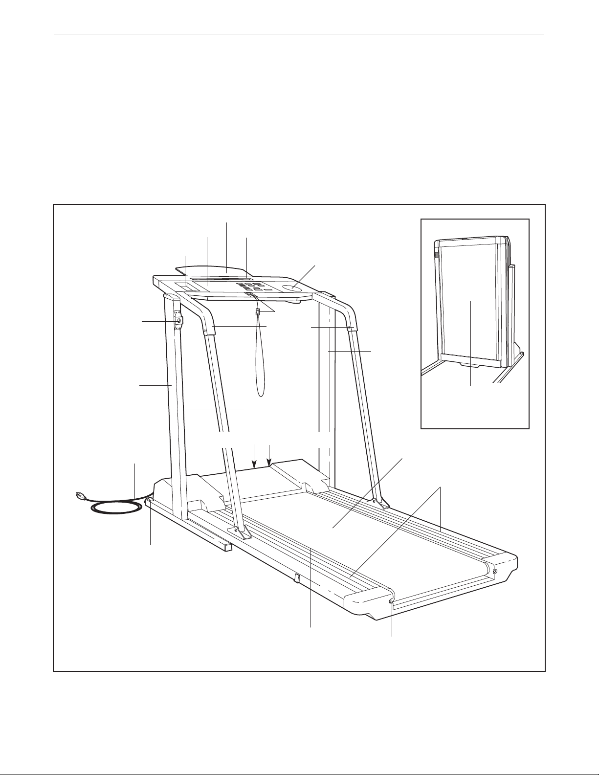
Book Rack
Console
Accessory Tray
Storage Latch
®
25 TL tread-
7
Towel Rack
Key/Clip
Handrails
ime (excluding holidays). To help us assist you,
T
lease note the product model number and serial num-
p
ber before calling. The model number of the treadmill
is 831.297763. The serial number can be found on a
decal attached to the treadmill (see the front cover of
this manual for the location).
Before reading further, please review the drawing
below and familiarize yourself with the parts that are
labeled.
Water Bottle Holder
(Water Bottle is
not included)
RIGHT
SIDE
LEFT SIDE
Power Cord
Front Wheel
Uprights
On/Off Switch
Cushioned Walking Platform
Circuit Breaker
Woodgrain-Finish
Cover Panel
(See page 18)
Walking Belt
Foot Rails
BACK
Rear Roller
Adjustment Bolt
5
Page 6
ASSEMBLY
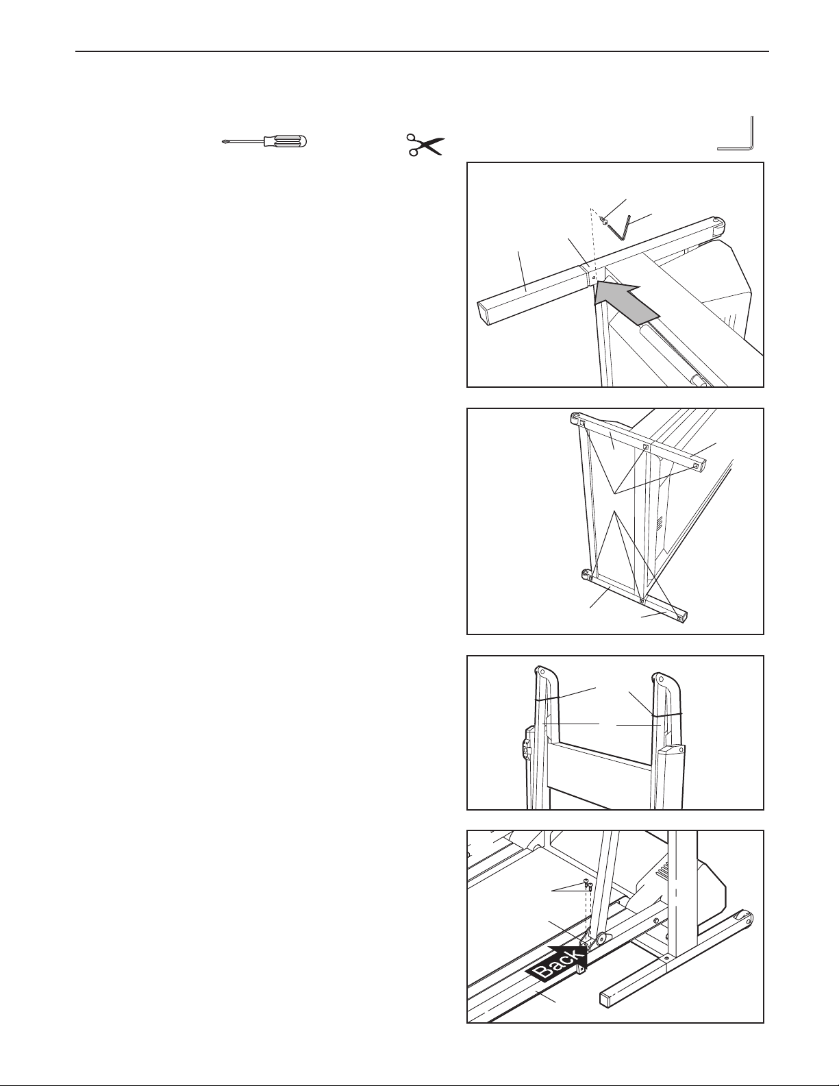
ssembly requires two people. Set the treadmill in a cleared area and remove the packing materials. Do not
A
dispose of the packing materials until assembly is completed. Assembly requires the included allen wrench ,
a phillips screwdriver and scissors (not included) .
1. Refer to the drawing on page 4 and identify the right
side of the treadmill. With the help of a second person,
carefully lay the treadmill on its right side; do not lay the
treadmill on its left side or the storage latch may be
damaged.
Firmly slide a Base Extension (76) into one side of the
Base (86). Using the Allen Wrench (89), tighten an
Extension Bolt (13) into the Base Extension and the Base.
While the treadmill is on its side, attach the other Base
Extension (not shown) in the same manner.
2. Attach six Base Pads (43) to the Base (86) and the Base
Extensions (76) in the indicated locations. Note: One
extra Base Pad may be included.
With the help of a second person, carefully raise the
treadmill to the upright position so the Base (86) and the
Base Extensions (76) are resting on the floor.
Refer to HOW TO LOWER THE TREADMILL FOR USE.
Follow the instructions to lower the treadmill.
1
13
89
86
76
2
76
86
43
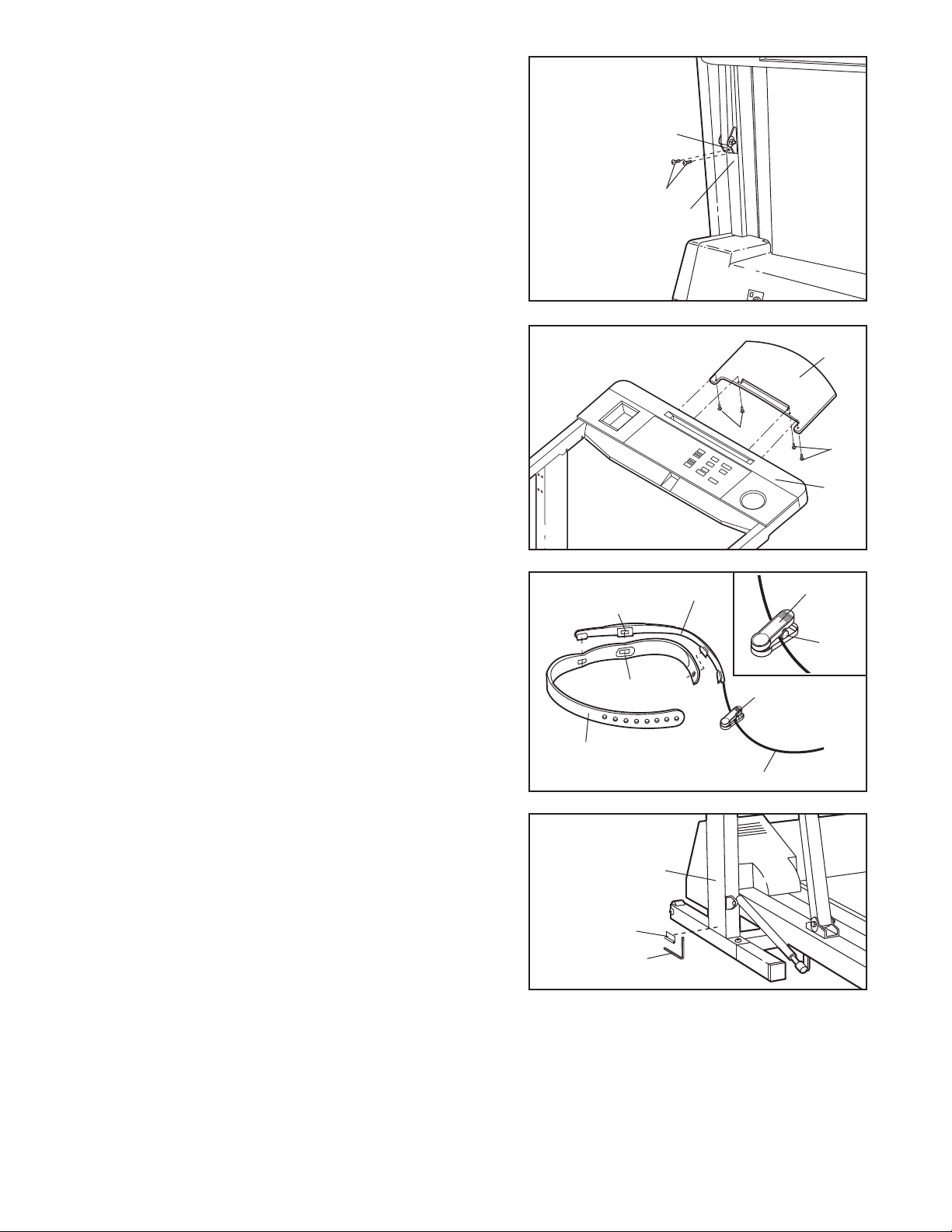
3. Cut the two Shipping Ties from the Handrails (61).
4. Remove the four Handrail Bracket Screws (15) from the
right side of the Frame (83). Position the
Bracket (42) over the four screw holes in the Frame.
Loosely thread two of the Screws into the back holes of
the Bracket and into the Frame as shown.
Repeat this step on the left side of the Frame (83).
right Handrail
6
86
3
4
15
42
83
76
Shipping
Ties
61
Page 7
5. Locate the section HOW TO FOLD THE TREADMILL
FOR STORAGE on page 18. Follow the instructions to
old the treadmill.
f
5
Thread two more Handrail Bracket Screws (15) into the
right Handrail Bracket (42) and Frame (83). Firmly
tighten all four Screws in the Bracket. Thread two more
Screws into the left Handrail Bracket and Frame (not
shown). Firmly tighten all four Screws in the Bracket.
6. Refer to HOW TO LOWER THE TREADMILL FOR USE
on page 19. Follow the instructions to lower the treadmill.
Align the holes in the Book Rack (101) with the holes in
the Console Base (85). Attach the Book Rack with the
four Console Screws (6) as shown.
7. Attach the Pulse Sensor (114) to the Headband (115).
Make sure that the sensor window is pressed through
the indicated hole in the Headband.
42
5
1
83
6
6
7
Sensor
Window
114
101
6
85
Clothes
Clip
Press open the clothes clip, and insert the pulse sensor
wire into the clothes clip.
sensor wire is resting against the hinge of the
clothes clip (see the inset drawing). The use of the
pulse sensor is explained on page 8.
8. Remove the backing from the Adhesive Clip (90). Press
the Clip onto the Upright Base (86) in the indicated location. Press the Allen Wrench (89) into the Clip.
9. Make sure that all parts are tightened before you use the treadmill.
place a mat under the treadmill. For information on ordering a mat, see REPLACEMENT
back cover.
Make sure that the pulse
Hole
115
Pulse Sensor Wire
8
86
90
89
Note: To protect the floor or carpet,
Hinge
Clothes Clip
PARTS on the
7
Page 8
HOW TO USE THE PULSE SENSOR
he unique headband-style pulse sensor is specially
T
designed for greater accuracy, comfort, and durability.
o get the best performance from the pulse sen-
T
sor, please read the following instructions.
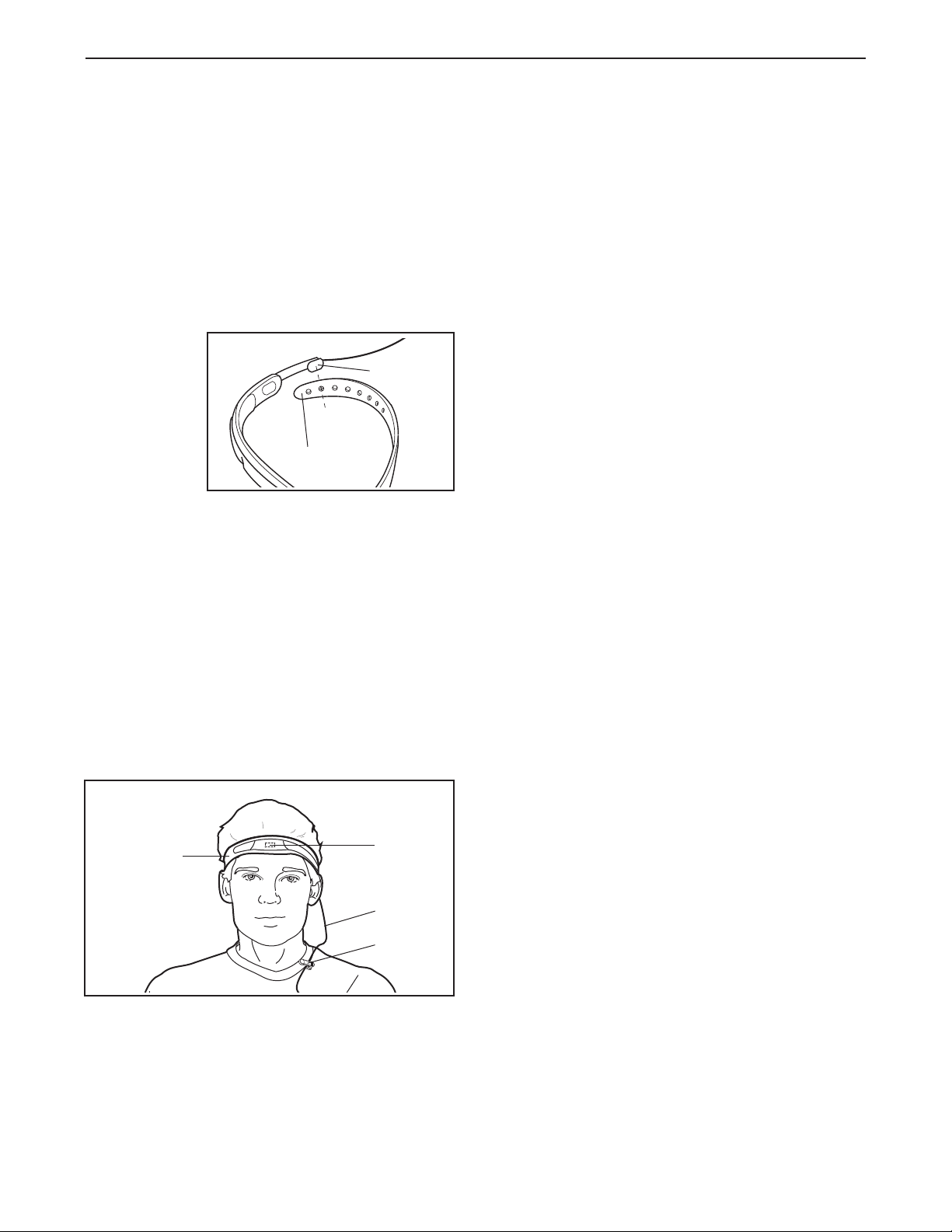
HOW TO ADJUST THE HEADBAND
For the pulse sensor to function properly, the headband should fit snugly around your head, without being
uncomfortable.
To adjust the
headband, insert the adjustment tab
through one
of the holes
in the headband.
Note:
Each time
you exercise, the headband may expand slightly during the
first few minutes of use. It may be necessary to
readjust the headband periodically.
HOW TO PUT ON THE PULSE SENSOR
Rub your forehead briefly to stimulate circulation. Put
on the headband as shown below, with the sensor window centered on your forehead. Make sure that there
is no hair between the sensor window and your forehead. Attach the clothes clip to your collar. The clothes
clip will reduce the movement of the pulse sensor wire,
helping to ensure accurate pulse readings.
Headband
Adjustment
Tab
ISPLAY). For the best results, remember the follow-
D
ing important guidelines:
1. Before putting on the headband, rub your forehead
briefly to stimulate circulation.
2. Make sure that the headband fits snugly, without
being uncomfortable. If the headband is too loose or
too tight, your pulse may not be detected.
3. The headband must be worn with the sensor window centered on your forehead. Make sure that
there is no hair between the sensor window and
your forehead. Make-up applied to the forehead
may interfere with pulse readings. Note: If the pulse
sensor does not detect your pulse when the sensor
window is centered on your forehead, try positioning
the sensor window above your right or left eyebrow.
Depending on the shape of your forehead, it may be
easier to detect your pulse from a different position.
4. Make sure that the pulse sensor wire is fully
plugged into the jack on the console.
5. Because your pulse constantly changes, the pulse
sensor will sample your pulse every few seconds.
When you first put on the pulse sensor, it may take
up to ten seconds for an accurate pulse to be shown.
6. Avoid excessive head movement during exercise.
7. The sensor window should be cleaned weekly when
the treadmill is used regularly. Moisten a cotton swab
with water, and carefully wipe the sensor window.
Headband
IMPORTANT: To avoid static build-up that may
damage the console, wear the pulse sensor only
while you are on the treadmill.
GUIDELINES FOR ACCURATE PULSE READINGS
The instructions on page 12 explain how the pulse
8
sensor is used with the console (see PULSE
Sensor
Window
Wire
Clothes
Clip
HOW TO SOLVE COMMON PULSE PROBLEMS
1. If you are wearing the pulse sensor and the NO
PULSE DETECTED indicator lights, refer to guidelines 2, 3, 4, 5, 6, and 7 above.
If the pulse shown in the PULSE display seems ex
2.
cessively high or low, refer to guideline 5.
If error code “E5” appears in the PULSE display,
3.
refer to guidelines 2, 3, 4, 5, 6, and 7.
4. If the letters “PLS” appear in the PULSE display,
refer to guidelines 2, 3, 4, 5, 6, and 7.
CLEANING THE PULSE SENSOR AND HEADBAND
Remove the headband from the pulse sensor. Wipe
the pulse sensor with a damp cloth; never immerse
the pulse sensor in water. Hand wash the headband
in mild detergent, gently wring it out, and let it air dry.
-
Page 9

OPERATION AND ADJUSTMENT
HE PERFORMANT LUBE
T
Your treadmill features a walking belt coated with
PERFORMANT LUBETM, a high-performance lubricant.
MPORTANT: Never apply silicone spray or other
I
ubstances to the walking belt or the walking plat-
s
form. They will deteriorate the walking belt and
cause excessive wear.
HOW TO PLUG IN THE POWER CORD
TM
ALKING BELT
W
DANGER: Improper connection
of the equipment-grounding conductor can
result in an increased risk of electric shock.
Check with a qualified electrician or serviceman if you are in doubt as to whether the
product is properly grounded. Do not modify
the plug provided with the product—if it will
not fit the outlet, have a proper outlet installed by a qualified electrician.
Your treadmill, like any other type of sophisticated
electronic equipment, can be seriously damaged by
sudden voltage changes in your home’s power.
Voltage surges, spikes, and noise interference can result from weather conditions or from other appliances
being turned on or off.
To decrease the possibility of your treadmill being damaged,
always use a surge
protector (not included) with your
treadmill.
1
Grounded Outlet Box
Grounding Pin
f electric shock. This product is equipped with a cord
o
having an equipment-grounding conductor and a
grounding plug.
protector, and plug the surge protector into an ap-
ropriate outlet that is properly installed and
p
rounded in accordance with all local codes and
g
ordinances.
This product is for use on a nominal 120-volt circuit,
and has a grounding plug that looks like the plug illustrated in drawing 1 below. A temporary adapter that
looks like the adapter illustrated in drawing 2 may be
used to connect the surge protector to a 2-pole receptacle as shown in drawing 2 if a properly grounded outlet is not available.
The temporary adapter should be used only until a
properly grounded outlet (drawing 1) can be installed
by a qualified electrician.
The green-colored rigid ear, lug, or the like extending
from the adapter must be connected to a permanent
ground such as a properly grounded outlet box cover.
Whenever the adapter is used it must be held in place
by a metal screw.
covers are not grounded. Contact a qualified electrician to determine if the outlet box cover is
grounded before using an adapter.
Grounding Plug
Plug the power cord into a surge
Some 2-pole receptacle outlet box
Treadmill Power Cord
Grounding Plug
Surge protectors are
sold at most hardware
stores and department
stores. Use only a ULlisted surge protector,
rated at 15 amps, with a
14-gauge cord of five
feet or less in length.
This product must be
grounded. If it should
malfunction or break
down, grounding provides a path of least resistance for electric current to reduce the risk
2
Metal Screw
Grounded Outlet
Grounded Outlet Box
Adapter
Lug
Grounding Pin
Grounding Plug
Grounding Pin
Surge Protector
9
Page 10

OFF
ON
DIAGRAM OF THE CONSOLE
Clip
Pulse Sensor Jack
Key
Note: If there is a thin sheet of clear plastic on the face of the console, remove it.
10
CAUTION: Before operating the
console, read the following precautions.
• Do not stand on the walking belt when turning on the power or starting the walking belt.
• Always wear the clip (see the drawing
above) while operating the treadmill. If the
key is pulled from the console, the walking
belt will stop.
• The treadmill is capable of high speeds.
Adjust the speed in small increments.
• The pulse sensor is not a medical device.
Various factors, including the user's movement, may affect the accuracy of pulse readings. The pulse sensor is intended only as
an exercise aid in determining pulse trends
in general.
• If you have heart problems, or if you are over
60 years of age and have been inactive,
not use the FAT BURN program or the AEROBIC program
. If you are taking medication
regularly, consult your physician to find
whether the medication will affect your exercise heart rate.
• To reduce the risk of electric shock, keep
the console dry, avoid spilling liquids on the
console, and use only a sealed water bottle.
do
FEATURES OF THE CONSOLE
The treadmill console offers an impressive array of features designed to make your workouts more effective
and enjoyable. When the console is in the manual mode,
the speed and incline of the treadmill can be changed
with a touch of a button. As you exercise, five displays
will provide continuous exercise feedback. Seven preset
programs are also offered: two WEIGHT LOSS programs
and two INTERVAL programs automatically control the
speed of the treadmill as they guide you through effective
workouts; the special FAT BURN program provides intensive fat-burning workouts; the AEROBIC program
helps you to achieve maximum cardiovascular benefits;
and the unique
FITNESS TEST program measures your
relative fitness level.
To use the manual mode, follow the steps on pages 11
through 13. To use the WEIGHT LOSS or INTERVAL
programs, see pages 13 and 14. To use the FAT BURN
or AEROBIC program, see pages 15 and 16. To use the
FITNESS TEST program, see pages 16 and 17.
Note:
The console can display speed and distance in either
miles or kilometers (see SPEED DISPLAY on page 12).
For simplicity, all instructions in this manual refer to miles.
Before beginning, make sure
that the on/off switch located
near the power cord is in the
“on” position. Plug in the power
“On”
Position
cord (see page 9). Note: If the
key is in the console when the
power cord is plugged in, the letters "PO" will flash in the
SPEED display. If this occurs, remove the key.
Page 11

HOW TO USE THE MANUAL MODE
Insert the key fully into the console.
1
Stand on the foot rails
and insert the key.
arious displays and in-
V
dicators will light. Find
the clip attached to the
key and slide it onto the
waistband of your clothing.
Select the MANUAL mode.
2
When the key is inserted, the manual
mode will automatically
be selected. The MAN
UAL CONTROL indica
tor will light. Note: If a
preset program has
been selected, press the MODE button repeatedly
to select the manual mode again.
Enter your weight, if desired.
-
-
3
Although it is not necessary to enter your weight and
age to use the manual mode, the CALORIES display will be more accurate if your weight and age
are entered. To enter your weight:
• Press the
WEIGHT increase or decrease button.
The letters
“LbS” will
flash in the
CALORIES display. Press one of the WEIGHT
buttons again. The current weight setting will then
be shown. Press the WEIGHT buttons again to
enter your weight. Each time one of the buttons is
pressed, the weight setting will change by 1
pound. If one of the buttons is held down, the
weight setting will change in increments of 5
pounds. After you have entered your weight, your
weight will be shown in the CALORIES display for
three seconds.
Enter your age, if desired.
4
To enter your age:
buttons again to enter your age. Each time one of
the buttons is pressed, the age setting will change
y 1 year. If one of the buttons is held down, the
b
age setting will change in increments of 5 years.
fter you have entered your age, your age will be
A
shown in the PULSE display for three seconds.
ote: Once you have entered your weight and age,
N
the numbers will be saved in the console’s memory,
even if the power cord is unplugged.
Put on the pulse sensor, if desired.
5
For the PULSE display to show your
pulse, the pulse sensor must be worn. To
put on the pulse sensor, see HOW TO
USE THE PULSE SENSOR on page 8. Plug the
pulse sensor fully into the jack on the front of the
console.
Press the SPEED increase button to start the
6
walking belt.
The speed of
the walking
belt is controlled with
the SPEED
increase and
decrease buttons. Each time one of the buttons is pressed, the
speed will change by 0.1 mile per hour (mph). The
buttons can be held down to change the speed
quickly. The speed range is 0.5 mph to 10 mph.
Press the SPEED increase button until the walking
belt begins to move at slow speed. Hold the
handrails and carefully begin walking. Change the
speed of the walking belt as desired by pressing the
SPEED buttons. Note: The walking belt can also be
started by pressing the START/PAUSE button. The
walking belt will begin to move at 0.5 mph. The
speed can then be adjusted with the SPEED buttons.
To stop the walking belt, press the START/PAUSE
button. All displays will pause and the TIME display
will begin to flash. To restart the walking belt, press
the SPEED buttons or the START/PAUSE button as
described above. Note: The walking belt can also be
stopped by pressing the STOP button. To restart the
walking belt, press the SPEED buttons or the
START/PAUSE button as described above.
• Press the AGE increase or decrease button. The
letters “AGE” will flash in the PULSE display.
Press one of the AGE buttons again. The current
age setting will then be shown. Press the AGE
Note: When the SPEED buttons are pressed, the
SPEED display will show the selected speed setting
for seven seconds. The display will then show the
actual speed of the walking belt.
11
Page 12

Change the incline of the treadmill, if desired.
TIME
Fitness Level
DIST. / INCLINE
7
he incline of the tread-
T
mill is controlled with the
NCLINE increase and
I
decrease buttons. Each
time one of the buttons
is pressed, the incline
will change by 0.5%.
The buttons can be held down to change the incline
quickly. The incline setting is shown in the DISTANCE/INCLINE display. The incline range is 1.5%
to 10%. Note: After the INCLINE buttons are
pressed, it may take a few seconds for the treadmill
to reach the selected incline setting.
Follow your progress with the five displays and
8
the TRAINING ZONE monitor.
• CALORIES display
This display shows
both the
and the number of
calories
burned. (See BURNING FAT on page 22
for an explanation of fat calories). Every seven
seconds, the display will change from one number
to the other. The FAT indicator beside the display
will light when the number of fat calories is shown.
Note: This display also shows the current weight
setting when the walking belt is stopped and the
WEIGHT buttons are pressed.
• PULSE display
For this display to operate, the pulse sensor must be worn (see
HOW TO USE THE
PULSE SENSOR on
page 8). After a few
seconds, the heart-shaped indicator beside the
PULSE display will flash each time your heart
beats, the NOT DETECTED indicator will darken,
and your pulse will be shown. Note: Because your
pulse constantly changes, the pulse sensor will
sample your pulse every few seconds.
up to ten seconds before an accurate pulse is
shown.
LINES FOR ACCURATE PULSE READINGS on
page 8.
total calories
fat
that you have
It may take
If your pulse is not shown, see GUIDE
•
SPEED display
This display shows
he current speed of
t
the walking belt.
hen the SPEED
W
buttons are pressed,
the display will show
the selected speed setting for seven seconds. The
display will then show the actual speed of the
walking belt.
Note: The speed can be displayed in either miles
per hour (mph) or kilometers per hour (kph). The
indicators beside the SPEED display will light to
show which unit of measurement is selected. To
change the unit of measurement, first hold down
the STOP button while inserting the key into the
console. An “E” (for English system [miles]) or “M”
(for Metric system [kilometers]) will appear in the
SPEED display. Press the SPEED increase button
to change the unit of measurement. Remove and
then reinsert the key.
TIME display
•
This display shows
the total time that
the walking belt has
been moving.
Note: When any program except the FITNESS TEST program is selected, the TIME display will show the time remaining in the program.
• DISTANCE/IN-
CLINE display
This display shows
both the distance
that the walking belt
has moved and the
current incline of the
treadmill. Every seven seconds, the display will
change from one number to the other. When the
INCLINE buttons are pressed, the display will
change to show the selected incline setting.
Note: If the MPH indicator beside the SPEED dis
play is lit, the distance will be displayed in miles. If
the KPH indicator is lit, the distance will be dis-
-
played in kilometers.
-
12
Note: This display also shows the current age set
ting when the walking belt is stopped and the AGE
buttons are pressed.
-
Page 13

• Training Zone Monitor
The training zone monitor
easures the approximate
m
intensity of your exercise.
he monitor’s five indicators
T
are described below:
• WARM UP & COOL
DOWN—Each workout
should begin with a warmup period and end with a
cool-down period. (See WORKOUT GUIDELINES on pages 22 and 23.) The WARM-UP &
COOL-DOWN indicator will light when your
workout intensity is ideal for warming up or cooling down.
• FAT BURN and MAXIMUM FAT BURN—To
burn fat effectively, you must exercise at a relatively low intensity level for a sustained period of
time. (See BURNING FAT on page 22.) If you
are exercising at the proper intensity level for
burning fat, the FAT BURN or MAXIMUM FAT
BURN indicator will light.
OW TO USE THE WEIGHT LOSS PROGRAMS
H
AND THE INTERVAL PROGRAMS
The WEIGHT LOSS programs and the INTERVAL
rograms automatically control the speed of the walking
p
belt as they guide you through effective workouts. The
WEIGHT LOSS programs focus on helping you to lose
unwanted pounds; the INTERVAL programs are
designed to build stamina. The WEIGHT LOSS programs
and the INTERVAL 1 program are 20-minute programs;
the INTERVAL 2 program is a 30-minute program. The
graphs on the left side of the console show how the
speed will change during each program. During the
WEIGHT LOSS 1 program, for example, the speed will
gradually increase during the first 10 minutes, and then
gradually decrease during the last 10 minutes. Each
program begins with a 2-minute warm-up period, and
ends with a 2-minute cool-down period.
Follow the steps below to use one of these programs.
Make sure that the key is fully inserted into the
1
console.
• AEROBIC—If your goal is to strengthen your
cardiovascular system, your exercise must be
“aerobic.” (See AEROBIC EXERCISE on page
22.) If you are exercising at the proper intensity
level for aerobic exercise, the AEROBIC indicator will light.
• PERFORMANCE—If your goal is high perfor-
mance athletic conditioning, you will need to exercise at a high intensity level. If you are exercising at the proper intensity level, the PERFORMANCE indicator will light.
When you are finished exercising, stop the walk-
9
ing belt and remove the key.
Step onto the foot rails and stop the walking belt.
Lower the treadmill to the lowest incline level.
Remove the key from the console and store the key
in a secure place. In addition, move the on/off switch
to the “off” position. (See the drawing near the bottom of page 10.)
Stand on the foot rails
and insert the key.
Various displays and
indicators will light.
Find the clip attached
to the key, and slide it
onto your waistband.
Select the WEIGHT LOSS 1, WEIGHT LOSS 2,
2
INTERVAL 1, or INTERVAL 2 program.
When the key is inserted,
the MANUAL CONTROL
indicator will light. To select
the WEIGHT LOSS 1 program, press the MODE
button. The WEIGHT
LOSS 1 indicator will light.
To select one of the other
programs, press the MODE
button repeatedly until the WEIGHT LOSS 2, INTERVAL 1, or INTERVAL 2 indicator lights. Note: If
the walking belt is moving, it will slow to a stop.
Enter your weight, if desired.
3
When a WEIGHT LOSS or INTERVAL program is
selected, the letters “LbS” will flash in the CALO
RIES display for seven seconds; the current weight
setting will then be shown. Although it is not neces
sary to enter your weight and age to use one of
these programs, the CALORIES display will be more
accurate if your weight and age are entered. If you
want to enter your weight, see step 3 on page 11.
-
-
13
Page 14

Enter your age, if desired.
4
fter you have completed step 3, the letters “AGE”
A
will flash in the PULSE display for seven seconds;
he current age setting will then be shown. If you
t
want to enter your age, see step 4 on page 11.
Put on the pulse sensor, if desired.
5
For the PULSE display
to show your pulse, the
pulse sensor must be
worn. To put on the
pulse sensor, see HOW
TO USE THE PULSE
SENSOR on page 8.
Plug the pulse sensor fully into the jack on the front
of the console.
Set a maximum speed for the program.
6
After you have
completed step
4, a number will
appear in the
SPEED display
and flash for
seven seconds.
This number shows the
walking belt will move during the program. The maximum speed setting can be from 3.0 mph to 8.5
mph. If you want to change the maximum speed setting, press the MAX. SPD. increase or decrease button. Note: The maximum speed setting will change
by 0.3 mph each time one of the MAX. SPD. buttons
is pressed, until it reaches 4.5 mph; the maximum
speed setting will then change by 0.5 mph each time
one of the buttons is pressed until it reaches 8.5 mph.
If the maximum speed setting is between 3.0 mph
and 5.0 mph, the walking belt will move at 1.5 mph
during the first 2 minutes and the last 2 minutes of
the program (the warm-up and cool-down periods).
speed range
The
be 1.5 mph. For example, if the maximum speed
setting is 5.0 mph, the
to 5.0 mph (a difference of 1.5 mph).
If the maximum speed setting is between 5.5 mph
and 8.5 mph, the walking belt will move at 3.0 mph
during the first 2 minutes and the last 2 minutes of
the program. The
program will be 2.0 mph.
maximum speed
during the rest of the program will
speed range
speed range
during the rest of the
that the
will be 3.5 mph
Press the START/PAUSE button to start the pro-
7
gram.
When the
TART/PAUSE
S
button is
pressed, the
TIME display
will begin
counting down
from 20 minutes (or 30 minutes if the INTERVAL 2
program is selected). After a moment, the walking
belt will begin to move. Hold the handrails and carefully begin walking.
As the program progresses, the speed of the walking belt will change periodically as shown by the
graphs on the left side of the console. The program
will continue until the time shown in the TIME display reaches zero. The walking belt will then slow to
a stop and the program will be completed.
During the last ten seconds of the program, the
treadmill will automatically adjust to the lowest
incline level. Keep your feet and objects from beneath the treadmill.
Note: The SPEED buttons will not respond while a
WEIGHT LOSS or INTERVAL program is selected. If
the program is too easy or too challenging, press the
MAX. SPD. buttons to set a new maximum speed.
The new maximum speed setting will be shown in the
SPEED display for 3 seconds. To stop the program
temporarily, press the START/PAUSE button. The
TIME display will begin to flash. To restart the program, press the START/PAUSE button again. The
program will resume and the walking belt will return to
the latest speed setting. To terminate the program before the program is completed, press the STOP button.
Change the incline of the treadmill, if desired.
8
When a WEIGHT LOSS or INTERVAL program is
selected, the incline of the treadmill can be changed
with the INCLINE buttons. See step 7 on page 12.
Follow your progress with the five displays and
9
the TRAINING ZONE monitor.
See TRAINING ZONE MONITOR on page 13.
When you are finished exercising, stop the
10
walking belt and remove the key.
Note:
14
Step onto the foot rails, stop the walking belt, and remove the key from the console.Store the key in a secure place.
“off” position. (See the drawing near the bottom of
page 10.)
In addition,
move the
on/off switch to the
Page 15

OW TO USE THE FAT BURN AND AEROBIC
H
PROGRAMS
he FAT BURN and AEROBIC programs automatically
T
ontrol the speed and incline of the treadmill to keep
c
your pulse within a predetermined range during your
workouts. Both programs are 30-minute programs. The
graphs on the left side of the console show how your
pulse will change during each program. Each program
begins with a warm-up period, and ends with a cooldown period.
To use one of these programs, follow the steps below.
Make sure that the key is fully inserted into the
1
console.
Stand on the foot rails
and insert the key.
Various displays and indicators will light. Find
the clip attached to the
key, and slide it onto the
waistband of your clothing.
Select the FAT BURN or AEROBIC program.
2
Press the MODE button
repeatedly until the FAT
BURN or AEROBIC indicator lights. Note: If the
walking belt is moving, it
will slow to a stop.
Enter your weight.
3
When the FAT BURN or AEROBIC program is selected, the letters “LbS” will flash in the CALORIES
display. You must enter your weight and age before
either of these programs can be started. To enter
your weight, see step 3 on page 11. If you have already entered your weight, you must press one of
the WEIGHT buttons to verify the weight setting.
Enter your age.
4
After you have completed step 3, the letters “AGE”
will flash in the PULSE display. To enter your age,
see step 4 on page 11. If you have already entered
your age, you must press one of the AGE buttons to
verify the age setting.
Put on the pulse sensor.
5
he pulse sensor must
T
be worn when the FAT
URN or AEROBIC
B
program is used. To put
on the pulse sensor,
see HOW TO USE
THE PULSE SENSOR on page 8. Plug the pulse
sensor fully into the jack on the front of the console.
Note: The FAT BURN and AEROBIC programs can
be started without your pulse being detected; however, the programs will automatically stop if your
pulse is not detected 2 minutes after the programs
are started.
Press the START/PAUSE button to start the pro-
6
gram.
When the START/
PAUSE button is
pressed, the TIME display will begin counting down from 30 minutes. After a moment,
the walking belt will
begin to move. Hold the handrails and carefully
begin walking.
As the program progresses, the speed and incline of
the treadmill will change periodically to keep your
pulse within a predetermined range, shown by the
graphs on the left side of the console. When the
time shown in the TIME display reaches zero, the
walking belt will slow to a stop and the program will
be completed.
of the program, the treadmill will automatically
adjust to the lowest incline level. Keep your feet
and objects from beneath the treadmill.
Note: If your pulse is
not detected during
the program, the NOT
DETECTED indicator
will light and the letters
“PLS” will flash in the
PULSE display. (See
GUIDELINES FOR ACCURATE PULSE READINGS on page 8.) If your pulse is not detected at the
end of any 2-minute period during the program (after
2 minutes, after 4 minutes, after 6 minutes, etc.), the
program will automatically stop.
Minor adjustments can be made to t
Note:
or incline of the treadmill during the program by
pressing the SPEED or INCLINE buttons. However
if you increase the speed, the incline will automati
cally decrease; if you decrease the speed, the incline will automatically increase. If you increase the
Note: During the last ten seconds
he speed
,
-
15
Page 16

incline, the speed will automatically decrease; if you
decrease the incline, the speed will automatically
ncrease.
i
your pulse near a predetermined setting.
ncline reaches the highest setting, the speed can-
i
not be decreased any further. When the incline
reaches the lowest setting, the speed cannot be
increased any further.
Note: To stop the program temporarily, press the
START/PAUSE button. The TIME display will begin
to flash. To restart the program, press the
START/PAUSE button again. The program will
resume and the walking belt will return to the latest
speed setting. To terminate the program before the
program is completed, press the STOP button.
Follow your progress with the five displays and
7
the TRAINING ZONE monitor.
See TRAINING ZONE MONITOR on pages 12 and
13.
When you are finished exercising, stop the walk-
8
ing belt and remove the key.
he console will always attempt to keep
T
When the
To use the FITNESS TEST program, follow the steps
below.
Make sure that the key is fully inserted into the
1
onsole.
c
Stand on the foot rails
and insert the key.
Various displays and
indicators will light.
Find the clip attached
to the key, and slide it
onto the waistband of
your clothing.
Select the FITNESS TEST program.
2
To select the FITNESS TEST program, press the
MODE button repeatedly until the FITNESS TEST indicator
lights. Note: If the
walking belt is moving, it will slow to a stop.
Step onto the foot rails, stop the walking belt, and remove the key from the console. Store the key in a
secure place. In addition, move the on/off switch to
the “off” position. (See the drawing near the bottom
of page 10.)
HOW TO USE THE FITNESS TEST PROGRAM
The FITNESS TEST program is designed to measure
your relative fitness level. For the best results, the
FITNESS TEST should be taken at a time when your
energy level is high. The FITNESS TEST should not be
taken if you have already exercised during the day.
The FITNESS TEST program consists of seven 4minute periods, and is followed by a 2-minute cooldown period. The speed and/or incline of the treadmill
will automatically increase at the beginning of each 4minute period.
16
Enter your weight.
3
When the FITNESS TEST program is selected, the
letters “LbS” will flash in the CALORIES display.
You must enter your weight and age before this program can be started. To enter your weight, see step
3 on page 11. If you have already entered your
weight, you must press one of the WEIGHT buttons
to verify the weight setting.
Enter your age.
4
After you have completed step 3, the letters “AGE”
will flash in the PULSE display. To enter your age,
see step 4 on page 11. If you have already entered
your age, you must press one of the AGE buttons to
verify the age setting.
Put on the pulse sensor.
5
The pulse sensor
must be worn when
the FITNESS TEST
program is used. To
put on the pulse sensor, see HOW TO
USE THE PULSE
SENSOR on page 8. Plug the pulse sensor fully into
the jack on the front of the console. Note: The FITNESS TEST program can be started without your
pulse being detected; however, the program will au
tomatically stop if your pulse is not detected 4 minutes after the program is started.
-
Page 17

Press the START/PAUSE button to start the pro-
6
gram.
When the START/
AUSE button is
P
pressed, the TIME display will begin counting
up. The CALORIES display will show “L 1”
(level 1), indicating that
the first 4-minute period of the FITNESS TEST program has begun. The incline of the treadmill will automatically adjust to 3.0%, and the walking belt will
begin to move at 1.5 mph. Hold the handrails and
carefully begin walking.
When the TIME display reaches 4 minutes, the
CALORIES display will show “L 2,” indicating that
the second 4-minute period has begun. The incline
will increase to 4%, and the speed will increase to
2.5 mph. At the beginning of each 4-minute period,
the speed and/or incline of the treadmill will automatically increase. The FITNESS TEST will continue
in this manner
until your pulse reaches 70% of your
maximum heart rate, and the current 4-minute period
is completed. The FITNESS TEST will then be completed, regardless of how many periods remain.
When the FITNESS TEST is completed, the letter
“C” will be shown in the CALORIES display, indicating that the cool-down period has begun. The TIME
display will count down from 2 minutes. When the
cool-down period is completed, the walking belt will
slow to a stop. Note: During the last ten seconds
of the cool-down period, the treadmill will automatically adjust to the lowest incline level. Keep
your feet and objects from beneath the treadmill.
After the program is completed, your fitness level
will be shown in the TIME display. There are ten fitness levels—fitness
level 10 (FL:10) is the
highest. Remember,
the FITNESS TEST is
intended only to indi
cate your relative fitness level.
-
after 8 minutes, etc.), the walking belt will slow to a
stop, the FITNESS TEST will end, and the TIME dis-
lay will show a fitness level of 0 (FL:00). (See
p
GUIDELINES FOR ACCURATE PULSE READ-
NGS on page 8.) The FITNESS TEST program
I
cannot be stopped temporarily and then restarted.
However, the program can be stopped at any time
by pressing the STOP button. The TIME display will
then show an estimated fitness level. If the STOP
button is pressed a second time, the MANUAL
mode will be selected.
When you are finished exercising, stop the walk-
7
ing belt and remove the key.
Step onto the foot rails, stop the walking belt, and remove the key from the console. Store the key in a
secure place. In addition, move the on/off switch to
the “off” position. (See the drawing near the bottom
of page 10.)
HOW TO SELECT THE INFORMATION MODE
The console features an information mode that keeps
track of the total time and distance accumulated on the
treadmill.
To access the information mode, hold down the STOP
button while inserting the key into the console. The
TIME display will show the total time accumulated on
the treadmill, in hours. The DISTANCE/INCLINE display
will show the total distance, in miles (if the total distance
exceeds 999 miles, the thousands and ten thousands
digits will be shown in the PULSE display). Note: The
SPEED display will show an “E” (for English system
[miles]) or “M” (for Metric system [kilometers]) (see
SPEED DISPLAY on page 12).
To exit the information mode, remove the key.
Note: The SPEED and INCLINE buttons will not respond while the FITNESS TEST program is selected.
If your pulse is not de
tected during the program, the NOT DETECTED indicator will
light and the letters
“PLS” will flash in the
PULSE display. If your
pulse is not detected
during the last thirty
seconds of any 4-minute period (after 4 minutes,
-
17
Page 18

HOW TO FOLD AND MOVE THE TREADMILL
HOW TO FOLD THE TREADMILL FOR STORAGE
Do not hold here
Before folding the treadmill, adjust the incline to the lowest
position. If the incline is not at the lowest position, the
readmill will be permanently damaged. Next, unplug the
t
power cord. Caution: You must be able to safely lift 45
pounds (20 kg) in order to raise, lower, or move the
treadmill.
1. Hold the treadmill with your hands in the locations shown
at the right.
not hold the treadmill in the locations indicated by the
arrows. To decrease the possibility of injury, bend
your legs and keep your back straight. As you raise
the treadmill, make sure to lift with your legs rather
than your back.
vertical position.
2.
Move your right hand to the position shown and hold the
treadmill firmly. Raise the treadmill until the storage latch
closes over the frame guide.
latch closes fully over the frame guide.
Caution: To avoid pinching your hands, do
Raise the treadmill about halfway to the
Make sure that the storage
To protect the floor or carpet from damage, place a
mat under the treadmill. Keep the treadmill out of direct sunlight. Do not leave the treadmill in the storage
position in temperatures above 85° Fahrenheit.
THE WOODGRAIN-FINISH COVER PANEL
When the treadmill is in the storage position, the woodgrainfinish cover panel will accent the decor of your room. If
desired, you can remove the cover panel to display the
black-finish frame cover instead. To remove the cover panel,
simply insert your fingers between the lower end of the cover
panel and the frame cover (see the arrow at the right). Pull
the cover panel off the panel fasteners, working your way up
until the cover panel is removed.
After the cover panel is removed, the panel fasteners can be
removed for a cleaner appearance. Using a phillips head
screwdriver, remove one of the panel screws and panel
fasteners from the frame cover. Tighten the panel screw
back into the frame cover. Repeat this process, removing
one panel fastener at a time, until all six panel fasteners
are removed. Press the removed panel fasteners onto the
fasteners on the back of the cover panel. Store the cover
panel away from moisture and dust.
Frame Cover
Frame
Cover
Panel Screw
Cover Panel
Frame
Guide
Cover Panel
Panel
Fastener
Fastener
Storage
Latch
Panel
Fastener
Closed
18
Page 19

HOW TO MOVE THE TREADMILL
Before moving the treadmill, convert the treadmill to the storage position as described above. Make sure that the stor-
age latch is closed fully over the frame guide.
1. Hold the upper ends of the treadmill. Place one foot on
the base as shown.
2. Tilt the treadmill back until it rolls freely on the front wheels.
Carefully move the treadmill to the desired location. Never
move the treadmill without tipping it back, or the base
pads may come off. To reduce the risk of injury, use
extreme caution while moving the treadmill. Do not attempt to move the treadmill over an uneven surface.
3. Place one foot on the base, and carefully lower the tread-
mill until it is resting in the storage position.
HOW TO LOWER THE TREADMILL FOR USE
1. Hold the upper end of the treadmill with your right hand as
shown. Using your left thumb, slide open the storage latch
and hold it open. Pivot the treadmill until the frame is past
the storage latch.
Storage
Latch
Base
Front Wheels
Opened
2. Hold the treadmill firmly with both hands, and lower the
treadmill to the floor. Caution: To avoid pinching your
hands, do not hold the treadmill in the locations indicated by the arrows. To decrease the possibility of injury, bend your legs and keep your back straight.
Do not hold here
19
Page 20

TROUBLE-SHOOTING
Tripped
Reset
OFF
ON
Most treadmill problems can be solved by following the steps below. Find the symptom that applies, and
follow the steps listed.
If further assistance is needed, call our toll-free HELPLINE at 1-800-736-6879, Monday through Saturday, 7
a.m. until 7 p.m. Central Time (excluding holidays).
1. SYMPTOM: THE POWER DOES NOT TURN ON
a. Make sure that the power cord is plugged into a surge protector, and that the surge protector is plugged into
a properly grounded outlet. (See HOW TO PLUG IN THE POWER CORD on page 9.) Use only a UL-listed
surge protector, rated at 15 amps, with a 14-gauge cord of five feet or less in length.
b. After the power cord has been plugged in, make sure that the key is fully inserted into the console. (See step
1 on page 11.)
c. Check the circuit breaker located on the treadmill near the
power cord. If the switch protrudes as shown, the circuit
breaker has tripped. To reset the circuit breaker, wait for five
c
Tripped
Reset
minutes and then press the switch back in.
d. Check the on/off switch located at the front of the treadmill
near the power cord. The switch must be in the “on” position.
d
“On”
Position
2. SYMPTOM: THE POWER TURNS OFF DURING USE
a. Check the circuit breaker located on the treadmill frame near the power cord (see 1. c. above). If the circuit
breaker has tripped, wait for five minutes and then press the switch back in.
b. Make sure that the power cord is plugged in.
c. Remove the key from the console. Reinsert the key fully into the console. (See step 1 on page 11.)
d. Check to make sure that the on/off switch is in the “on” position. (See 1. d. above.)
e. If the treadmill still will not run, please call our toll-free HELPLINE.
3. SYMPTOM: THE WALKING BELT SLOWS WHEN WALKED ON
a. Use only a UL-listed surge protector, rated at 15 amps, with a 14-gauge cord of five feet or less in length.
b. If the walking belt still slows when walked on, please call our toll-free HELPLINE.
4. SYMPTOM: AN ERROR CODE (“E2,” “E3,” “E4,” OR “E5”) APPEARS ON THE CONSOLE
a. Error code “E2” may appear in the SPEED display if the SPEED increase or START/PAUSE button is
pressed and no movement of the walking belt is detected within seven seconds. Remove the key, wait for
ten seconds, and then reinsert it. Make sure that you stand on the foot rails of the treadmill each time you
start the walking belt. If the error code appears again, call our toll-free Customer Service Department. Do not
operate the treadmill until the problem is corrected.
b. Error code
“E3” may appear in the SPEED display if the speed of the walking belt surges above the se
lected speed setting. Remove the key, wait for ten seconds, and then reinsert it. If the error code appears
again, call our toll-free Customer Service Department. Do not operate the treadmill until the problem is cor-
20
rected.
-
Page 21

c. Error code “E4” may appear in the SPEED display if the walking belt is moving at a slow speed, and there is
excessive stress on the motor. Remove the key, wait for ten seconds, and then reinsert it. If you weigh over
00 pounds, it may be helpful to increase the incline of the treadmill. If the error code appears again, call our
2
toll-free Customer Service Department. Do not operate the treadmill until the problem is corrected.
d. Error code
SENSOR on page 8, and PULSE DISPLAY on page 12.
5. SYMPTOM: THE PULSE SENSOR DOES NOT FUNCTION PROPERLY
a. See HOW TO USE THE PULSE SENSOR on page 8, and PULSE DISPLAY on page 12.
6. SYMPTOM: THE WALKING BELT IS OFF-CENTER WHEN WALKED ON
a. If the walking belt has shifted to the left, first remove the key and
UNPLUG THE POWER CORD. Using the allen wrench, turn the
left rear roller adjustment bolt clockwise 1/4 of a turn. Plug in the
power cord, insert the key and run the treadmill for a few minutes. Repeat until the walking belt is centered.
b. If the walking belt has shifted to the right, first remove the key
and
turn the left rear roller adjustment bolt counterclockwise 1/4 of a
turn. Plug in the power cord, insert the key and run the treadmill
for a few minutes. Repeat until the walking belt is centered.
“E5” may appear in the PULSE display if a pulse error occurs. See HOW TO USE THE PULSE
a
UNPLUG THE POWER CORD. Using the allen wrench,
b
7. SYMPTOM: THE TREADMILL SITS UNEVENLY ON THE FLOOR
a. Make sure that the six base pads are attached to the treadmill. See assembly step 2 on page 6.
21
Page 22

CONDITIONING GUIDELINES
WARNING: Before beginning
this or any exercise program, consult your
physician. This is especially important for individuals over the age of 35 or individuals
ith pre-existing health problems.
w
Training Zone (Beats/Min.)
Age
20 138-167 133-162
5 136-166 132-160
2
Unconditioned Conditioned
The pulse sensor is not a medical device.
Various factors, including your movement,
may affect the accuracy of heart rate readings.
The sensor is intended only as an exercise aid
in determining heart rate trends in general.
The following guidelines will help you to plan your exercise program. Remember—these are general guide
lines. For more detailed information about exercise,
obtain a reputable book or consult your physician.
EXERCISE INTENSITY
Whether you want to burn fat, strengthen your cardiovascular system, or increase your athletic performance, you can tailor your exercise to your specific
goals. The key to achieving the desired results is to exercise with the proper intensity.
Burning Fat
To burn fat effectively, you must exercise at a relatively
low intensity level for a sustained period of time.
During the first few minutes of exercise, your body
uses easily accessible
ergy. Only after the first few minutes of exercise does
your body begin to use stored
If your goal is to burn fat, adjust the speed and incline
of the treadmill until the FAT BURN indicator is lit. (See
TRAINING ZONE MONITOR on page 13.)
Aerobic Exercise
If your goal is to strengthen your cardiovascular sys
tem, your exercise must be “aerobic.” Aerobic exercise
is activity that requires large amounts of oxygen for
prolonged periods of time. This increases the demand
on the heart to pump blood to the muscles, and on the
lungs to oxygenate the blood. The proper intensity
level for aerobic exercise can be found by using your
pulse as a guide. As you exercise, your pulse should
be kept at a level between 70% and 85% of your maximum possible heart rate. This is known as your train
ing zone. You can find your training zone in the table
at the top of this page. Training zones are listed according to age and physical condition.
During the first few months of your exercise program,
22
carbohydrate calories
fat calories
for en-
for energy.
30 135-164 130-158
35 134-162 129-156
40 132-161 127-155
45 131-159 125-153
50 129-156 124-150
55 127-155 122-149
-
-
-
60 126-153 121-147
65 125-151 119-145
70 123-150 118-144
75 122-147 117-142
80 120-146 115-140
85 118-144 114-139
keep your pulse near the low end of your training zone
as you exercise. After a few months of regular exercise, your pulse can be gradually increased until it is
near the middle of your training zone as you exercise.
You can measure your pulse using the pulse sensor.
Exercise for about four minutes, and then measure
your pulse immediately. If your pulse is too high or too
low, adjust the intensity of your exercise. It may also
be helpful to adjust the speed and incline of the treadmill until the AEROBIC indicator is lit. (See TRAINING
ZONE MONITOR on page 13.)
Performance Training
If your goal is high performance athletic conditioning,
adjust the speed and incline of the treadmill until the
PERFORMANCE indicator is lit. (See TRAINING
ZONE MONITOR on page 13.)
WORKOUT GUIDELINES
Each workout should include three parts: (1) a warmup, (2) training zone exercise, and (3) a cool-down.
Warm-up
Warming up prepares the body for exercise by increas
ing circulation, delivering more oxygen to the muscles
and raising the body temperature. Begin each workout
with 5 to 10 minutes of stretching and light exercise to
warm up (see SUGGESTED STRETCHES on page 23).
-
Page 23

Training Zone Exercise
fter warming up, increase the intensity of your exer-
A
cise until your pulse is in your training zone for 20 to
0 minutes. (During the first few weeks of your exer-
6
cise program, do not keep your pulse in your training
zone for longer than 20 minutes.) Breathe regularly
and deeply as you exercise—never hold your breath.
Cool-down
Finish each workout with 5 to 10 minutes of stretching
SUGGESTED STRETCHES
to cool down. This will increase the flexibility of your
muscles and will help to prevent post-exercise problems.
Exercise Frequency
To maintain or improve your condition, complete three
workouts each week, with at least one day of rest between workouts. After a few months, you may complete up to five workouts each week if desired.
The key to success is to make exercise a regular and
enjoyable part of your everyday life.
The correct form for several basic stretches is shown in the
drawings below. Move slowly as you stretch—never bounce.
1. Toe Touch Stretch
Stand with your knees bent slightly and slowly bend forward
from your hips. Allow your back and shoulders to relax as you
reach down toward your toes as far as possible. Hold for 15
counts, then relax. Repeat 3 times. Stretches: Hamstrings,
back of knees and back.
2. Hamstring Stretch
Sit with one leg extended. Bring the sole of the opposite foot
toward you and rest it against the inner thigh of your extended
leg. Reach toward your toes as far as possible. Hold for 15
counts, then relax. Repeat 3 times for both legs. Stretches:
Hamstrings, lower back and groin.
3. Calf/Achilles Stretch
With one leg in front of the other, reach forward and place your
hands against a wall. Keep your back leg straight and your
back foot flat on the floor. Bend your front leg, lean forward
and move your hips toward the wall. Hold for 15 counts, then
relax. Repeat 3 times for both legs. To cause further stretching
of the achilles tendons, bend your back leg as well. Stretches:
Calves, achilles tendons and ankles.
1
2
3
4
4. Quadriceps Stretch
With one hand against a wall for balance, reach back and
grasp one foot with your other hand. Bring your heel as close
to your buttocks as possible. Hold for 15 counts, then relax.
Repeat 3 times for both legs. Stretches: Quadriceps and hip
muscles.
5. Inner Thigh Stretch
Sit with the soles of your feet together and your knees outward. Pull your feet toward your groin area as far as possible.
Hold for 15 counts, then relax. Repeat 3 times. Stretches:
Quadriceps and hip muscles.
5
23
Page 24

PART LIST—Model No. 831.297763 R0597A
ey No. Part No. Qty. Description
K
104725 2 Upright Endcap Bolt
1
2 129600 1 Rear Roller Guard
3 100427 10 Nut
4 121421 3 Upright Bracket Bolt
013322 10 Screw
5
6 126996 10 Console Screw
132549 1 Ground Wire
7
8 112669 1 Clevis Pin
9 106334 1 Cotter Pin
10 132449 2 Hex-Head bolt
11 014088 1 Small Star Washer
12 117806 2 Base Wheel Bolt
13 013484 2 Extension Bolt
14 013300 20 Screw
15 013540 8 Handrail Bracket Screw
16 133072 5 Belly Pan Fastener
17 013456 4 Endcap Bolt
18 105444 2 Adjustment Bolt (Short)
19 014127 4 Adjustment Washer
20 013456 4 Frame Isolator Screw
21 013576 4 Latch Frame Guide Screw
22 134300 2 Isolator
23 134302 8 Spring Cushion
24 128272 8 Platform Screw
25 054023 3 Wire Clip
26 128986 1 Tension Spring
27 123470 1 Spring Sleeve
28 121576 3 Roller Tension Nut
29 132456 2 Spacer
30 135665 1 Right Endcap Foot
31 127597 6 Endcap Fastener
32 114270 2 Incline Motor Spacer
33 120630 18 Small Screw
34 120354 2 Upright Pivot Bolt
35 013547 1 Motor Tension Bolt
36 014117 1 Star Washer
37 122812 1 Motor Tension Washer
38 120867 1 Motor Tension Nut
39 107503 1 Motor Pivot Bolt
40 132434 4 Spring
41 132440 1 Upright Endcap (left)
42 132422 2 Handrail Bracket
43 129740 7 Base Pad
44 125677 5 Hood Anchor
45 052012 2 Front Wheel
46 103833 2 Base Extension Endcap
47 132394 5 Hood Bracket
48 125819 4 Plastic Stand-off
49 130251 2 Frame Guide
50 130993 1 Choke
51 134347
138863 8
52
109382 1 Circuit Breaker
53
54 131753 1 Storage Latch Bracket
55 131738 1 Storage Latch
56 132466 1 Electronics Bracket
57 109265
134303
58
134305 1 Front Roller/Pulley
59
60 134570 2 Foot Rail
61 132426 2 Handrail
62 132565 1 Left Handrail Arm
63 134571 1 Hood
64 134346 2 Handrail Arm Spacer
65 134388 2 Frame Spacer
66 134572 1 Console
67 137356
68 135866
69 139085
70 124669 1 Power Cord
71 124695 1 Grommet
Bracket
1
Upright Plug
Belt Guide
2
1 Rear Roller
Motor
1
Motor Belt
1
Incline Motor
1
ey No. Part No. Qty. Description
K
2 134574 1 Wire Harness
7
73 137676 6 Cover Fastener
74 129004 2 Wire Harness Grommet
75 134331 1 Shock
6 132435 2 Base Extension
7
77 134576 1 Power Supply w/Clips
8 137858 1 Controller
7
79 138058 1 Incline Leg
80 132453 1 Belly Pan
81 136203 1 Endcap Plug
82 136880 1 Rear Roller Cover
83 NSP 1 Frame
84 134578 1 Walking Platform
85 137465 1 Console Base
86 136073 1 Upright/Base
87 132455 1 Left Endcap Foot
88 100498 1 Magnet
89 126040 1 Allen Wrench
90 016028 2 Adhesive Clip
91 118153 1 Reed Switch Wire
92 134577 1 Walking Belt
93 136869 1 Frame Cover
94 137409 1 Adjustment Bolt (Long)
95 109370 1 Incline Disk
96* 137357 1 Motor/Pulley/Flywheel/Fan
97 126747 1 Pulley/Flywheel/Fan
98 134649 1 Frame Cover Panel
99 136377 2 Latch Spring
100 132424 1 Right Handrail Arm
101 135025 1 Book Rack
102 132441 1 Right Upright Endcap
103 016057 5 8” Wire Tie
104 131605 1 Latch Warning Decal
105 119038 1 Key/Clip
106 129232 2 Storage Warning Decal
107 135004 1 Choke Plate
108 129168 5 Cover Screw
109 134338 1 Incline Cover Shield
110 134337 1 Incline Cover
111 134594 6 Cover Screw/Panel Screw
112 125871 1 Motor/Controller Wire
113 129639 1 Battery Cover
114 127731 1 Pulse Sensor/Clothes Clip
115 126481 1 Headband
116 119163 1 On/Off Switch
117 119070 1 Speed Disk
118 138691 1 Optic Switch Bracket
119 012152 2 Small Nut
120 122125 1 Optic Switch Nut
121 102955 2 Optic Switch
122 102959
123
124
125 116892 1 Incline Bracket
126 013375 1 Incline Bolt
127 119425 3 Incline Nut
128 131562
129
130
131 014073 6 Handrail Washer
132 135922 2 Handrail Cover
*
# These parts are not illustrated
126911 2
014063 2 Roller Cover Washer
013529
133333 6 Clip
# 127860 12 Fastener
# 107771 1 8” White Wire, Male/Female
# 109407 1 4” Black Wire, 2 Female
# 102643 1 8” Green Ground Wire
# 112083 1 8” Blue Wire, 2 Female
102246
#
139004
#
Includes all parts shown in the box
Small Bolt
2
Optic Switch Wire Harness
Latch Pad
2
5 Anchor Screw
8” White Wire, 2 Female
1
User’s Manual
1
Page 25

55
66
85
6
6
6
100
3
10
102
1
5
127
126
69
15
10
15
10
8
9
13
45
3
12
61
86
76
46
75
75
76
13
46
5
54
39
67
38
36
37
35
68
14
44
47
14
44
47
29
48
77
56
78
14
29
79
47
14
51
14
50
14
14
44
47
3
14
44
47
16
16
80
16
31
31
31
31
31
81
17
94
124
82
17
18
61
10
3
62
3
41
1
3
4
42
60
59
58
24
24
84
60
19
26
27
28
21
49
34
57
33
33
111
111
111
111
40
23
23
40
23
22
22
20
20
93
83
43
43
43
43
53
129
5
5
72
72
14
44
124
23
74
3
3
88
89
90
90
14
91
71
70
92
99
96*
97
28
103
14
7
104
106
EXPLODED DRAWING—Model No. 831.297763 R0597A
106
30
87
28
21
49
108
109
110
108
108
3
118
119
117
122
121
120
123
122
11
121
95
119
123
114
115
64
107
64
65
74
112
19
19
129
129
129
128
73
73
73
98
73
131
131
32
32
132
132
52
15
15
130
2
4
3
42
101
6
6
5
5
5
63
105
113
116
125
131
131
131
130
15
127
18
127
52
52
52
52
Page 26

Model No. 831.297763
The model number and serial number of your PROFORM®725 TL
treadmill are listed on a decal attached to the frame. See the front
cover of this manual to find the location of the decal.
QUESTIONS?
If you find that:
• you need help assembling or
operating the PROFORM
TL treadmill
• a part is missing
• or you need to schedule repair
service
call our toll-free HELPLINE
®
725
1-800-736-6879
Monday–Saturday, 7 am–7 pm
Central Time (excluding holidays)
REPLACEMENT
PARTS
If parts become worn and need
to be replaced, call the following
toll-free number
All replacement parts are available for immediate purchase or
special order when you visit your nearest SEARS Service Center.
To request service or to order parts by telephone, call the toll-free
numbers listed at the left.
When requesting help or service, or ordering parts, please be prepared to provide the following information:
• The NAME OF THE PRODUCT (PROFORM®725 TL treadmill)
• The MODEL NUMBER OF THE PRODUCT (831.297763)
• The PART NUMBER OF THE PART (see the EXPLODED
DRAWING and PART LIST included in this manual)
• The DESCRIPTION OF THE PART (see the EXPLODED DRAWING and PART LIST included in this manual).
1-800-FON-PART
(1-800-366-7278)
Part No. 139004 G01973AC R0597A Printed in USA © 1997 Sears, Roebuck and Co.
 Loading...