


Proform 831297482 Owner’s Manual
PRO.FORM
cRas " WA
SW/ARS
Model No. 831.297482
Serial No.
Theserialnumberisfoundinthe location
shownbelow.Wdtetheserialnumberin
thespaceaboveforfuturereference.
Sedal Number
/Decal
L
_ fii_il _L _.ii ............
K_
EQUIPMENT
"onll=n_.l i| II [e] l_il:
HELPLINE!
1-800-73d-6879
USER'S MANUAL
SEARS, ROEBUCK AND CO., HOFFMAN ESTATES, IL 60179

TABLE OF CONTENTS
IMPORTANT PRECAUTIONS .......
BEFORE YOU BEGIN ......... . ...................................................... "...
ASSEMBLY ....................................... _..................................
°=*_•°°°°,°°t,°°.=t=°°°,°.•°°•°°°°°°°o°G°°•°°°,°°,°°_*•°°2
_°°°°4
°o°°_5
OPERATION AND ADJUSTMENT ........................................................
HOW TO FOLD AND MOVE THE TREADMILL ..............................................
TROUBLE-SHOOTING .................................................................
CONDITIONING GUIDELINES ...........................................................
.... 11
.... 12
.... 14
ORDERING REPLACEMENT PARTS .................................................. Back Cover
FULL 90 DAY WARRANTY ........ Back Cover
• ,,°,*0* ° = e• °° = ° = o° °° o• °° o_ °° o,* ,el ., o,, = • =°_ • °.t,o
Note: A HARDWARE IDENTIFICATION CHART, an EXPLODED DRAWING, and a PART LIST are attached to
the center of this manual. Please save them for future reference.
IMPORTANT PRECAUTIONS
.2
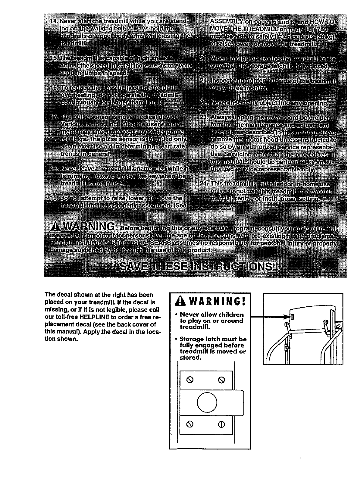
The decal shown at the right has been
placed on your treadmill. If the decal is
missing, or if it is not legible, please call
our toll-free HELPLINE to order a free re-
placement decal (see the back cover of
this manual). Apply the decal In the Ioca-
tion shown.
AWARNIHG!
• Never allow children
to play on or around
treadmdh
• Storage latch must be
fully en.qa.ged before
treadmill is moved or
stored.
ool
© ]
o o]
/F
BEFORE YOU BEGIN
Thank you for sele_ng the PROFORM* CROSSWALK
PLUS treadmill, The CROSSWALK PLUS treadmill
blends advanced lechnology with Innovat_vedesign to
letyou enjoy an excellent form of cardiovascular exer-
cise inthe convenience and privacy of your home.
For your benefit, read this manual carefully before
using the treadmill. If you have additional questions,
please call our toll-free HELPLINE at 1-800-736-6879,
Monday through Saturday, 7 a.m, until 7 p.m. Central
AccessoryTray
Storage
Handrails
Time (excluding holidays). To help us assist you,
please note the product model number and serial num-
ber before calling. The model number of the treadmill
is 8,31.2.97482.The sedal number can be found on a
decal attached to the treadm_ (see the frontcover of
this manual forthe locatiOn).
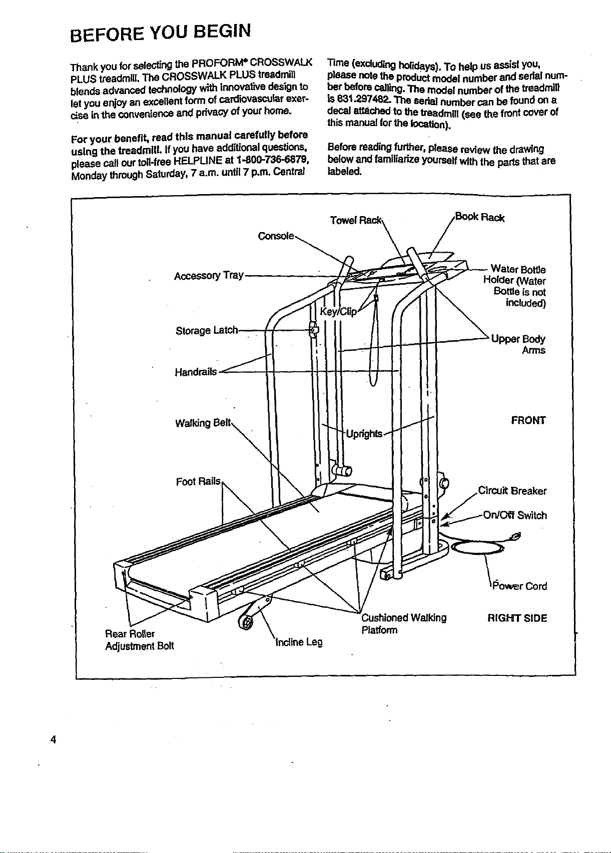
Before reading further, please review the drawing
below and familiarize yourselfWith the parts that are
labeled.
r Bottle
Holder (Water
Bottle is not
included)
Upper Body
Arms
Rear Roller
Adjustment Bolt
FRONT
Walking Belt_X
Foot Rails
Cord
WatkJng RIGHT SiDE
Platform
4
ASSEMBLY
CAUTION: Read and follow step I below before removing the restraining tie (see drawing 1). If the restrain-
Ing tie is removed prematurely, sedous bodily injury m=iy result. Assembly requires two people. Set the tread-
millin a cleared area and remove the packing matedals except for the restraining tie. Do not dispose of the
packing matedals until assembly is completed. Use the HARDWARE IDENT[RCATION CHART in the center ofthis
manual to identify the parts used in assembly. Assembly requires the Included allen wrench L==_, a phillips
screwdriver _z_), and two adjustable wrenches _.
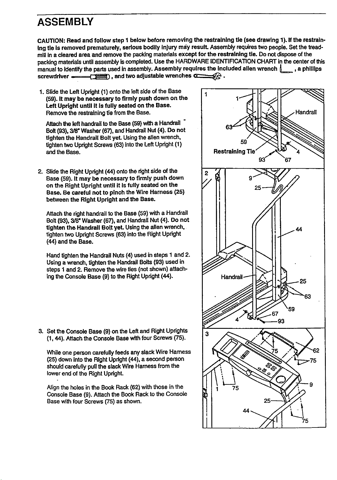
1. Slide the Left Updght (1) onto the left side of the Base
(59). It may be necessary to firmly push down on the
Left Upright until It Is fully seated on the Base.
Remove the restraining tie from the Base.
Attach the left handrail to the Base (59) witha Handrail "
Bolt(93), 3/8" Washer (67), and Handrail Nut (4). Do not
tighten the Handrail Bolt yet. Usingthe ellen wrench,
tighten two Upright Screws (63) intothe Left Upright (1)
and the Base.
2. Slide the Right Upright (44) ontothe dght side of the
Base (59). It may be necessary to firmly push down
on the Right Upright until it Is fully seated on the
Base, Be careful not to pinch the Wire Harness (25)
between the Right Upright and the Base.
Restraining
59
Attach the right handrail to the Base (59) with a Handrail
Bolt(93), 3/8" Washer (67), and Handrail Nut (4). Do not
tighten the Handrail Bolt yeL Using the allen wrench,
tighten two Upright Screws (63) into the Right Updght
(44) and the Base.
Hand tighten the Handrail Nuts (4) used insteps I and 2.
Using a wrench, tighten the Handrail Bolts (93) used in
steps I and 2. Remove the wire ties (not shown) attach-
ingthe Console Base (9) to the RightUpright (44).
3. Set the Console Base (9) on the Left and Right Uprights
(1, 44). Attach the Console Base with four Screws (75).
While one person carefullyfeeds any slack Wire Harness
(25) down intothe Right Updght (44), a second person
should carefully pull the slack Wire Harness from the
lower end ofthe Right Updght.
Align the holes in the Book Rack (62) with those in the
Console Base (9). Attach the Book Rack to the Console
Base with four Screws (75) as shown.
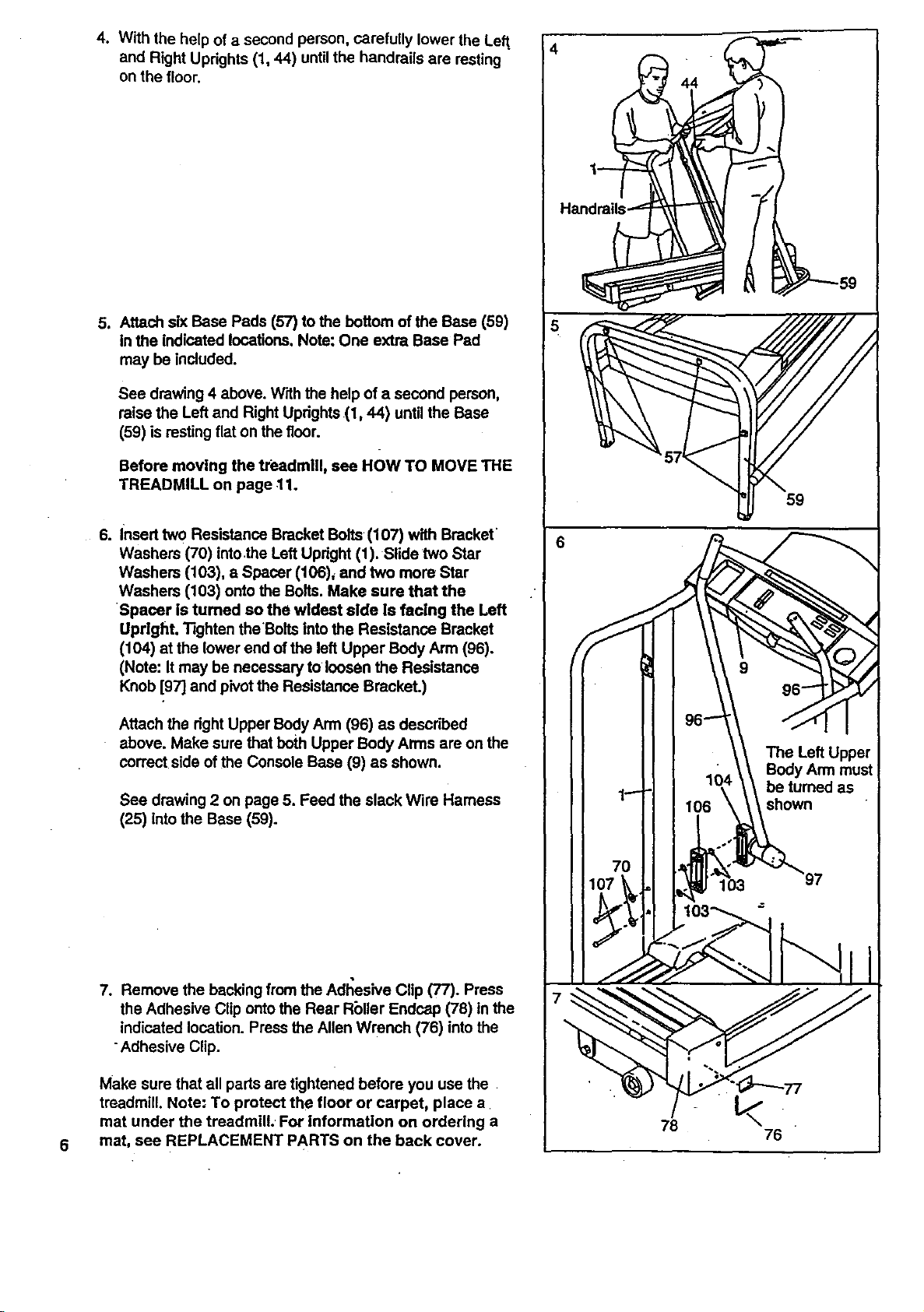
4. With the help of a second person, carefully lower the Left,
and Right Updghts (1, 44) until the handrails are resting
on the floor.
J Attach siXBase Pads (57) to the bottom of the Base (59)
in the indicated locations. Note: One extra Base Pad
may be included.
See drawing 4 above. With the help of a second person,
raise the Left and Right Uprights (1,44) until the Base
(59) is resting flat on the floor.
Before moving the treadmill, see HOW TO MOVE THE
TREADMILL on page 11.
59
6. Insert two Resistance Bracket Bolts (107) with Bracket
Washers (70) intothe Left Updght (1). Slide two Star
Washers (103), a Spacer (106)_ and two more Star
Washers (103) onto the Bolts. Make sure that the
Spacer is turned so the wideet aide is facing the Left
Upright. Tighten theBolts into the Resistance Bracket
(104) at the lower end of the left Upper Body Arm (96).
(Note: It may be necessary to loosen the Resistance
Knob [97] and pivot the Resistance Bracket.)
Attach the dght Upper Body Arm (96) as descdbed
above. Make sure that both Upper Body Arms are onthe
correct side of the Console Base (9) as shown.
See drawing 2 on page 5. Feed the slack Wire Harness
(25) intothe Base (59).
7. Remove the backing from the Adl';esive Clip (77). Press
the Adhesive Clip onto the Rear Rbller Endcap (78) in the
indicated location. Press the Allen Wrench (76) into the
Adhesive Clip.
Make sure that all pads are tightened before you use the
treadmill. Note: To protect the floor or carpet, place a
mat under the treadmill. For information on ordering a
mat, see REPLACEMENT PARTS on the back cover.
6
78
76