

Page 1
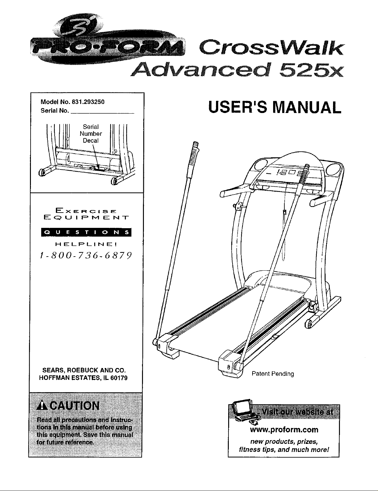
Model No. 831.293250
Serial No.
Serial
Number
Decal
Ex E: R C I S E:
EQUIPMENT
CrossWalk
Advanced 525x
USER'S MANUAL
HELPLINE!
1-800-736-d879
SEARS, ROEBUCK AND CO.
HOFFMAN ESTATES, IL 60179
Patent Pending
www.proform.com
new products, prizes,
fitness tips, and much more!
Page 2

CrossWalk
Advanced 525x
TABLE OF CONTENTS
IMPORTANT PRECAUTIONS ................................................................. 3
BEFORE YOU BEGIN ....................................................................... 5
ASSEMBLY ............................................................................... 6
OPERATION AND ADJUSTMENT ............................................................. 8
HOW TO FOLD AND MOVE THE TREADMILL .................................................. 22
TROUBLESHOOTING ...................................................................... 24
CONDITIONING GUIDELINES ............................................................... 26
ORDERING REPLACEMENT PARTS .................................................. Back Cover
FULL 90 DAY WARRANTY ........................................................... Back Cover
Note: An EXPLODED DRAWING and a PART LIST are attached in the center of this manual.
Page 3

IMPORTANT PRECAUTIONS
Page 4
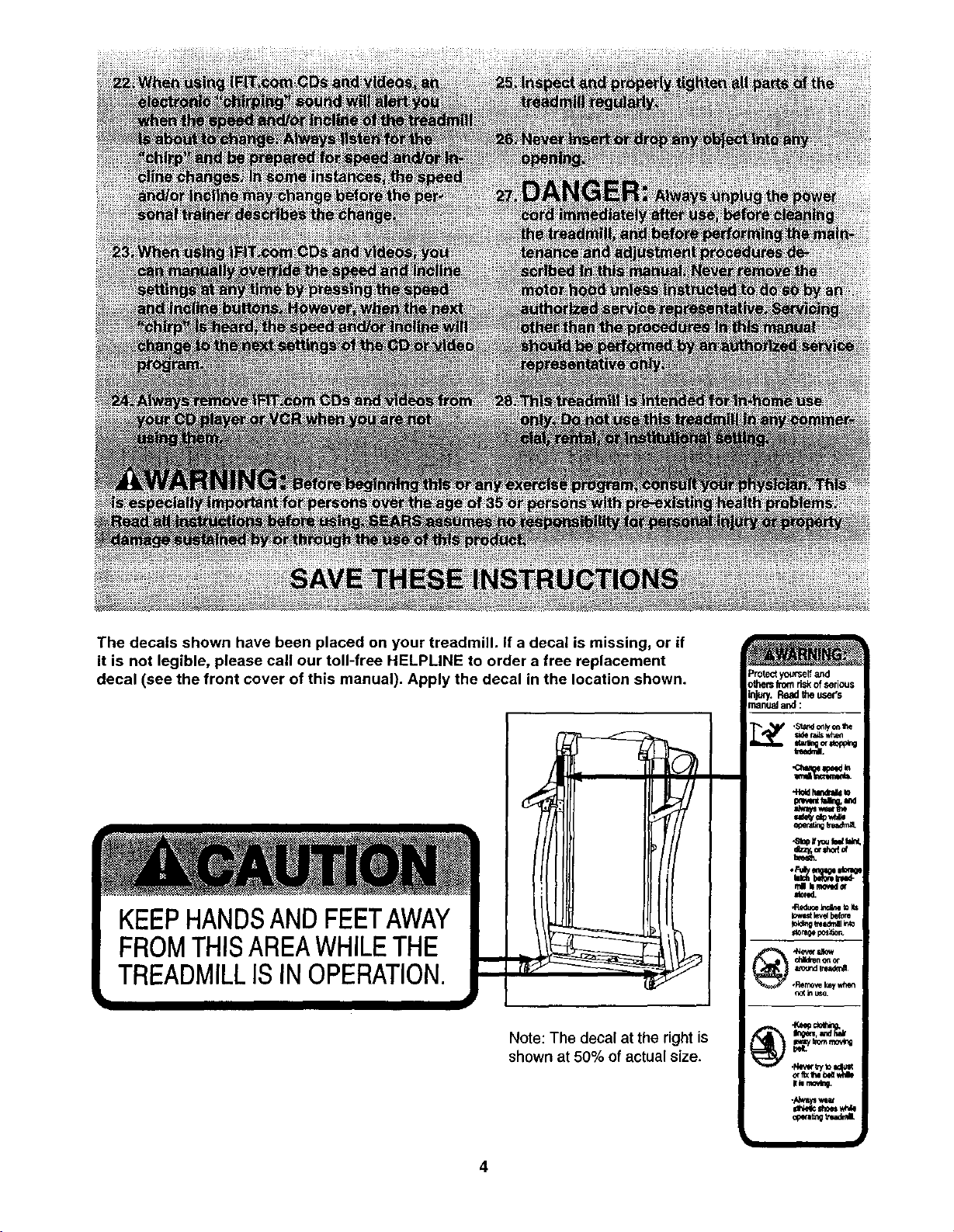
The decals shown have been placed on your treadmill. If a decal is missing, or if
it is not legible, please call our toll-free HELPLINE to order a free replacement
decal (see the front cover of this manual). Apply the decal inthe location shown.
KEEPHANDSANDFEETAWAY
FROMTHISAREAWHILETHE
TREADMILLISINOPERATION.
Note: The decal at the right is
shown at 50% of actual size.
Page 5
BEFORE YOU BEGIN
Thank you for selecting the new PROFORM ®CROSS-
WALK ADVANCED 525x treadmill. The CROSSWALK
ADVANCED 525x treadmill combines advanced tech-
nology with innovative design to help you get the most
from your exercise program in the convenience of your
home. And when you're not exercising, the unique
CROSSWALK ADVANCED 525x can be folded up, re-
quiring less than half the floor space of other treadmills.
For your benefit, read this manual carefully before
using the treadmill. If you have additional questions,
please call our toll-free HELPLINE at 1-800-736-6879,
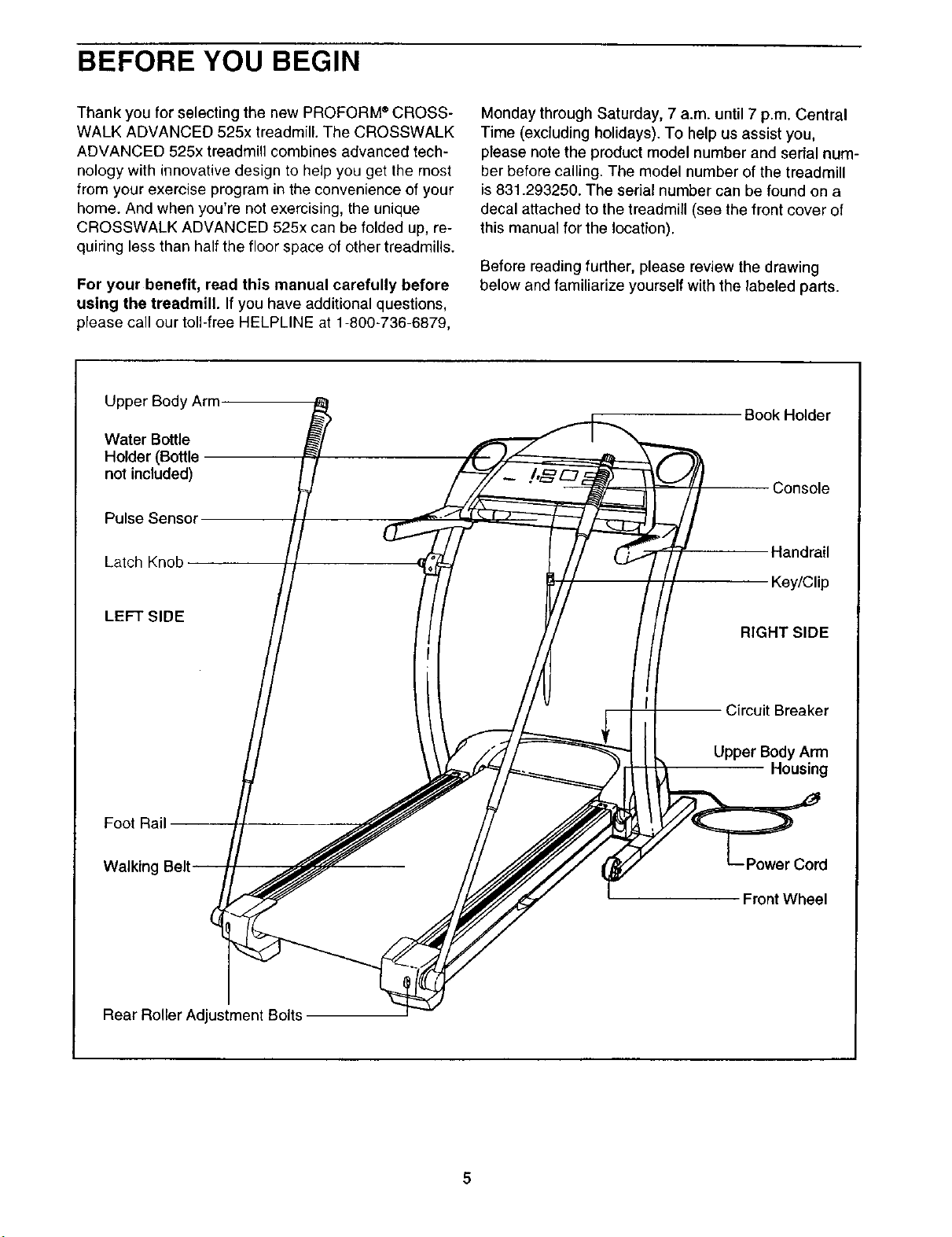
Upper Body Arm
Water Bottle
Holder (Bottle
not included)
Pulse Sensor
Latch Knob
Monday through Saturday, 7 a.m. until 7 p.m. Central
Time (excluding holidays). To help us assist you,
please note the product model number and serial num-
ber before calling. The model number of the treadmill
is 831.293250. The serial number can be found on a
decal attached to the treadmill (see the front cover of
this manual for the location).
Before reading further, please review the drawing
below and familiarize yourself with the labeled parts.
Book Holder
Console
Handrail
Key/Clip
LEFT SIDE
Foot Rail
Walking
Rear Roller Adjustment Bolts
RIGHT SIDE
Circuit Breaker
Upper Body Arm
Housing
r Cord
Front Wheel
Page 6
ASSEMBLY
Assembly requires two persons. Set the treadmill in a cleared area, and remove all packing materials except
for the plastic ties around the upper body arms. Do not dispose of the packing materials untilassembly is com-
pleted. Assembly requires your own Phillips screwdriver (_ and rubber mallet _.
Note: The underside of the treadmill walking belt iscoated with high-performance lubricant. During shipping, a
small amount of lubricant may be transferred to the top of the walking belt or the shipping carton. This is a normal
condition and does not affect treadmill performance. If there is lubricant on top of the walking belt, simply wipe off
the lubricant with a soft cloth and a mild, non-abrasive cleaner.
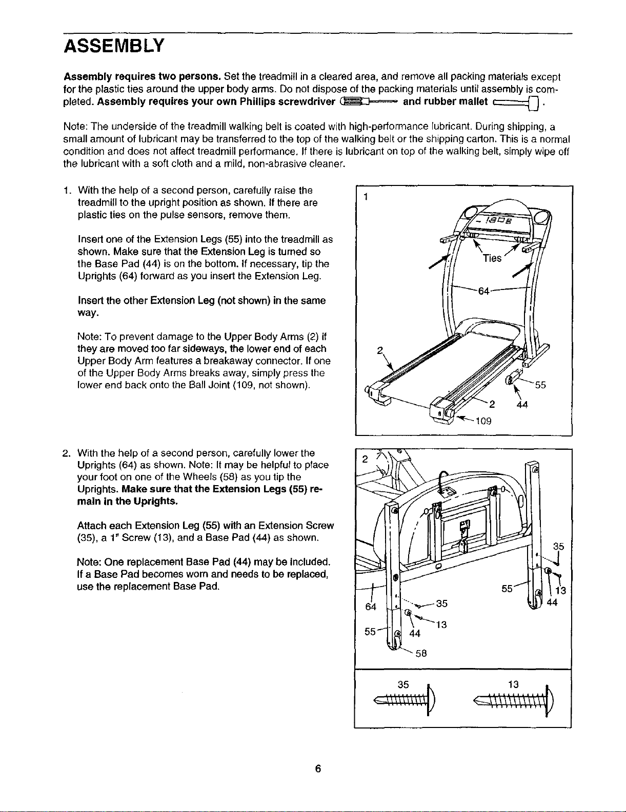
1. With the help of a second person, carefully raise the
treadmiU to the upright position as shown. If there are
plastic ties on the pulse sensors, remove them.
Insert one of the Extension Legs (55) into the treadmill as
shown. Make sure that the Extension Leg is turned so
the Base Pad (44) is on the bottom. If necessary, tip the
Uprights (64) forward as you insert the Extension Leg.
Insert the other Extension Leg (not shown) inthe same
way.
Note: To prevent damage to the Upper Body Arms (2) if
they are moved too far sideways, the lower end of each
Upper Body Arm features a breakaway connector. If one
of the Upper Body Arms breaks away, simply press the
lower end back onto the Ball Joint (109, not shown).
2
2. With the help of a second person, carefully lower the
Uprights (64) as shown. Note: It may be helpful to place
your foot on one of the Wheels (58) as you tip the
Uprights. Make sure that the Extension Legs (55) re-
main in the Uprights.
Attach each Extension Leg (55) with an Extension Screw
(35), a 1" Screw (13), and a Base Pad (44) as shown.
Note: One replacement Base Pad (44) may be included.
If a Base Pad becomes wom and needs to be replaced,
use the replacement Base Pad.
35
113
44
44
58
6
Page 7
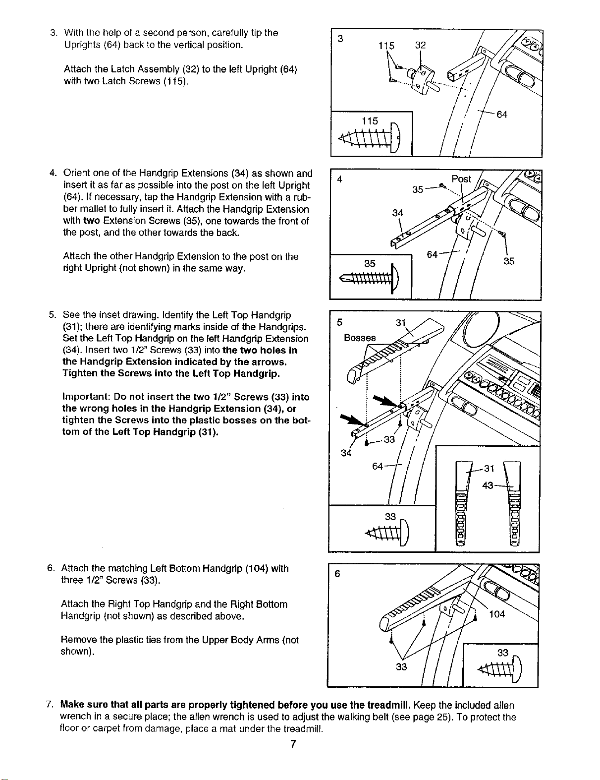
3. With the help of a second person, carefully tip the 3
Uprights (64) back to the vertical position. 115 32
Attach the Latch Assembly (32) to the left Upright (64)
with two Latch Screws (115).
4. Orient one of the Handgrip Extensions (34) as shown and
insert it as far as possible into the post on the left Upright
(64). If necessary, tap the Handgrip Extension with a rub-
ber mallet to fully insert it. Attach the Handgrip Extension
with two Extension Screws (35), one towards the front of
the post, and the other towards the back.
Attach the other Handgrip Extension to the post on the
right Upright (not shown) in the same way.
5. See the inset drawing. Identify the Left Top Handgrip
(31); there are identifying marks inside of the Handgdps.
Set the Left Top Handgdp on the left Handgdp Extension
(34). Insert two 1/2" Screws (33) into the two holes in
the Handgrip Extension indicated by the arrows.
Tighten the Screws into the Left Top Handgrip.
Important: Do not insert the two 1/2" Screws (33) into
the wrong holes in the Handgrip Extension (34), or
tighten the Screws into the plastic bosses on the bot-
tom of the Left Top Handgrip (31).
4 Post
35 ---_ ....
34 ..
35
6. Attach the matching Left Bottom Handgdp (104) with
three 1/2" Screws (33).
Attach the Right Top Handgrip and the Right Bottom
Handgrip (not shown) as described above.
Remove the plastic ties from the Upper Body Arms (not
shown).
7. Make sure that all parts are properly tightened before you use the treadmill. Keep the included allen
wrench ina secure place; the amenwrench is used to adjust the walking belt (see page 25), To protect the
floor or carpet from damage, place a mat under the treadmill.
7
k
33
104
Page 8
OPERATION AND ADJUSTMENT
THE PERFORMANT LUBE TM WALKING BELT
Your treadmill features a walking belt coated with
PERFORMANT LUBE TM, a high-performance lubricant.
IMPORTANT: Never apply silicone spray or other
substances to the walking belt or the walking plat-
form. Such substances will deteriorate the walking
belt and cause excessive wear.
HOW TO PLUG IN THE POWER CORD
Your treadmill, like any other type of sophisticated
electronic equipment, can be seriously damaged by
sudden voltage changes in your home's power.
Voltage surges, spikes, and noise interference can
result from weather conditions or from other appli-
ances being turned on or off. To decrease the pos-
sibility of your treadmill being damaged, always
use a surge suppresser with your treadmill (see
drawing 1 at the right). To purchase a surge sup-
pressor, see your local SEARS dealer or call 1-800-
366-7278 and order part number 146148.
an equipment-grounding conductor and a grounding
plug. Plug the power cord into a surge suppressor,
and plug the surge suppressor into an appropriate
outlet that is properly installed and grounded in
accordance with all local codes and ordinances.
Important: The treadmill is not compatible with
GFCI-equipped outlets.
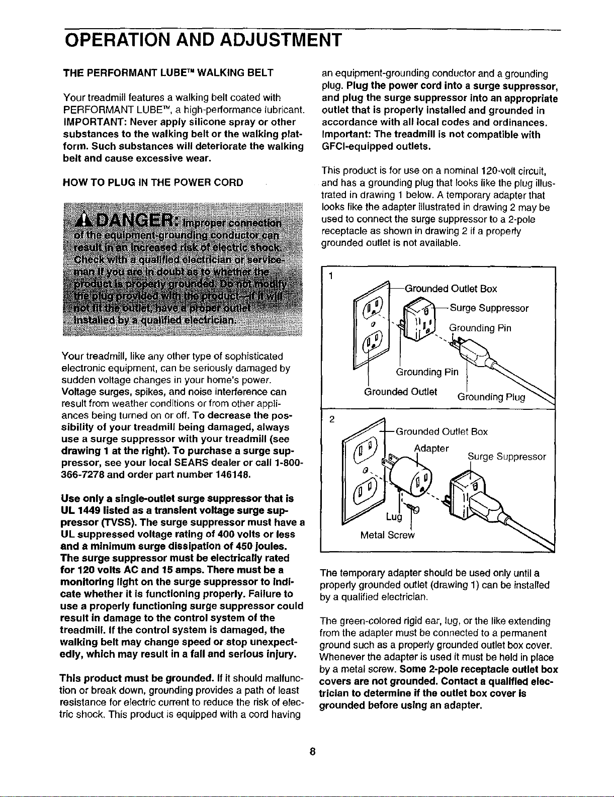
This product is for use on a nominal 120-volt circuit,
and has a grounding plug that looks like the plug illus-
trated in drawing 1 below. A temporary adapter that
looks like the adapter illustrated in drawing 2 may be
used to connect the surge suppressor to a 2-pole
receptacle as shown in drawing 2 if a properly
grounded outlet is not available.
_Grounded Outlet Box
_€_. I _SurgeSuppressor
_ !Zii_rn____II _. I"_ i',_J Grounding Pin
Grounded Outlet Grounding Plug"_
2
Grounded Outlet Box
,_,d(._, ,_'%_-_1 apter Surge Suppressor
Use only a single-outlet surge suppressor that is
UL 1449 listed as a transient voltage surge sup-
pressor (TVSS). The surge suppressor must have a
UL suppressed voltage rating of 400 volts or less
and a minimum surge dissipation of 450 Joules.
The surge suppressor must be electrically rated
for 120 volts AC and 15 amps. There must be a
monitoring light on the surge suppressor to indi-
cate whether it is functioning properly. Failure to
use a properly functioning surge suppressor could
result in damage to the control system of the
treadmill. If the control system is damaged, the
walking belt may change speed or stop unexpect-
edly, which may result in a fall and serious injury.
This product must be grounded. If itshould malfunc-
tion or break down, groundingprovides a path of least
resistance for electric current to reduce the riskof elec-
tric shock. This product is equipped with a cord having
Metal Screw _'_
The temporary adapter should be used only until a
propedy grounded outlet (drawing 1) can be installed
by a qualified electrician.
The green-colored rigid ear, lug, or the like extending
from the adapter must be connected to a permanent
ground such as a properly grounded outlet box cover.
Whenever the adapter is used itmust be held in place
by a metal screw. Some 2-pole receptacle outlet box
covers are not grounded. Contact a qualified elec-
trician to determine if the outlet box cover is
grounded before using an adapter.
Page 9
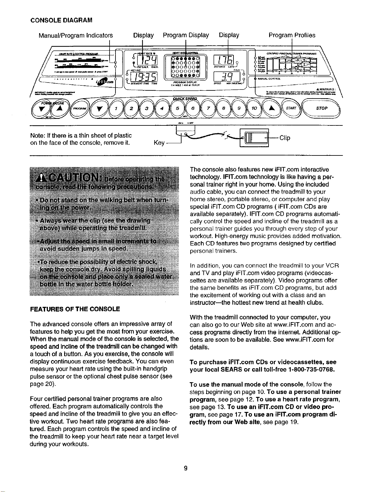
CONSOLEDIAGRAM
Manual/Program Indicators Display Program Display Display
Note: If there is a thin sheet of plastic
on the face of the console, remove it.
The console also features new iFIT.com interactive
technology. IFIT.com technology is like having a per-
sonal trainer right in your home. Using the included
audio cable, you can connect the treadmill to your
home stereo, portable stereo, or computer and play
special iFIT.com CD programs ( iFIT.com CDs are
available separately). IFIT.com CD programs automati-
cally control the speed and incline of the treadmill as a
personal trainer guides you through every step of your
workout. High-energy music provides added motivation.
Each CD features two programs designed by certified
personal trainers.
Program Profiles
STOP
FEATURES OF THE CONSOLE
The advanced console offers an impressive array of
features to help you get the most from your exercise.
When the manual mode of the console is selected, the
speed and incline of the treadmill can be changed with
a touc h of a button. As you exercise, the console will
display continuous exercise feedback. You can even
measure your heart rate using the built-in handgrip
pulse sensor or the optional chest pulse sensor (see
page 20).
Four certified personal trainer programs are also
offered. Each program automaticallycontrols the
speed and incline of the treadmill to give you an effec-
tive workout. Two heart rate programs are also fea-
tured. Each program controls the speed and incline of
the treadmill to keep your heart rate near a target level
during your workouts.
In addition, you can connect the treadmill to your VCR
and TV and play iFIT.com video programs (videocas-
settes are available separately). Video programs offer
the same benefits as iFIT.com CD programs, but add
the excitement of working out with a class and an
instructor--the hottest new trend at health clubs.
With the treadmill connected to your computer, you
can also go to our Web site at www.iFIT.com and ac-
cess programs directly from the internet. Additional op-
tions are soon to be available. See www.iFIT.com for
details.
To purchase iFIT.com CDs or videocassettes, see
your local SEARS or call toll-free 1-800-735-0768.
To use the manual mode of the console, follow the
steps beginning on page 10. To use a personal trainer
program, see page 12. To use a heart rate program,
see page 13. To use an iFIT.com CD or video pro-
gram, see page 17. To use an iFIT.com program di-
rectly from our Web site, see page 19.
Page 10
HOWTOTURN ON THE POWER
B Plug in the power cord (see page 8). Make sure
that the circuit breaker isin the reset position (see
page 24).
B .Stand on the foot rails of the treadmill. Find the clip
attached to the key (see the drawing on page 9)
and slide the clip onto the waistband of your
clothes. Next, insert the key into the console. After
a moment, the displays and various indicators will
light. Test the clip by carefully taking a few
steps backward until the key is pulled from the
console. If the key is not pulled from the con-
sole, adjust the position of the clip.
D Insert the key fully into the console.
See HOW TO TURN ON THE POWER above.
B Select the manual mode.
When the key is in- $ _
serted, the manual ! i'--I " " = I
mode will be selected I I1_-_,,,,,_o,,_o_ I
and the Manual Control
indicator will light. If a
program has been
selected, press the Program button repeatedly to
reselect the manual mode.
the Quick Speed buttons. Note: The console can
display speed and distance in either miles or
kilometers. For simplicity, all instructions in
this section refer to miles.
To stop the walking belt, press the Stop button.
The Time/Incline/Segment Time display will begin
to flash. To restart the walking belt, press the Start
button or the Speed A button.
Note: During the first few minutes that the treadmill
is used, inspect the alignment of the walking belt,
and align it ifnecessary (see page 25).
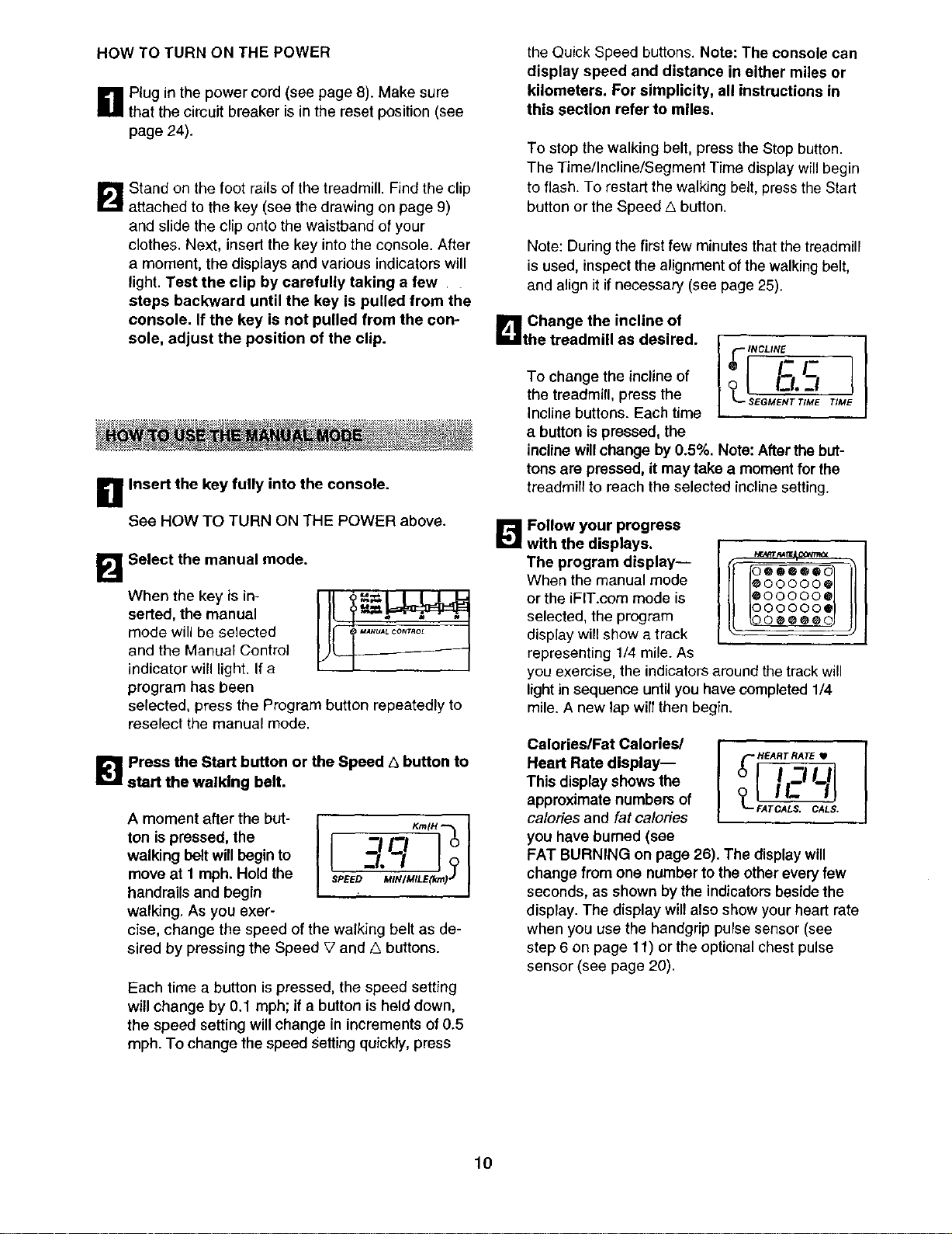
L_ Change the incline of
the treadmill as desired.
To change the incline of
the treadmill, press the
Incline buttons. Each time
a button is pressed, the
incline willchange by 0.5%. Note: After the but-
tons are pressed, it may take a moment for the
treadmill to reach the selected incline setting.
_ Follow your progress
with the displays.
The program display--
When the manual mode
or the iFIT.com mode is
selected, the program
@00000_
@00000_
O00000S
display will show a track
representing 1/4 mile. As
you exercise, the indicators around the track will
light in sequence until you have completed 1/4
mile. A new lap will then begin.
_"_ Press the Start button or the Speed A button to
start the walking belt.
A moment after the but-
ton is pressed, the
walking belt will begin to
move at 1 mph. Hold the
$PE_D MIN/MILE(km)"
?
handrails and begin
walking, As you exer-
cise, change the speed of the walking belt as de-
sired by pressing the Speed V and G buttons.
Each time a button is pressed, the speed setting
will change by 0.1 mph; if a button is held down,
the speed setting will change in increments of 0.5
mph. To change the speed Setting quickly, press
Heart Rate display--
This display shows the
approximate numbers of _L_
calories and fat calories _TCA_S.CA_S.
yOUhave burned (see
FAT BURNING on page 26). The display will
change from one number to the other every few
seconds, as shown by the indicators beside the
display. The display will also show your heart rate
when you use the handgrip pulse sensor (see
step 6 on page 11) orthe optional chest pulse
sensor (see page 20).
lO
Page 11

TimellnclinelSegment
Time display--When
the manual mode or the
iFIT.com mode is se-
lected, this display will
show the elapsed time
and the inclinelevel of the treadmill. The display
will change from one number to the other every
few seconds, as shown by the indicators beside
the display. When a personal trainer program or a
heart rate program is selected, the display will
show the time remaining in the program, the time
remaining in the current segment of the program,
and the incline level. Note: Each time the incline
changes, the display will show the current incline
setting for several seconds.
Distance/Laps
display--This display
shows the distance that
you have walked or run
and the number of 1/4-
mile laps you have com-
pleted. The display will change from one number
to the other every few seconds, as shown by the
indicator beside the display.
Speed/Min-Mile
display--This display
shows the speed of the
walking belt and your
current pace (pace is
measured in minutes per
mile). The display will change from one number to
the other every few seconds, as shown by the in-
dicators beside the display. Note: Each time the
speed changes, the display will show the current
speed setting for several seconds.
o t I-i'_1
_'-- SEGMENT TIME
I -I -I
L iCjJo,
ols_ LAPS--'
KmlH -_
-!121 °
/ J. I/?
SPEED MINIMILE(krn)*"
To reset the displays, press the Stop button, re-
move the key, and then reinsert the key.
r_ Measure your heart rate, if desired.
Note: Before using the handgrip pulse sensor,
make sure that your hands are clean.
To measure your
heart rate, stand
on the foot rails
and place your
hands on the
metal contacts on
the handrail. Your
palms must be
resting on the con-
tacts--avoid moving your hands. When your
pulse is detected, the Heart Rate indicatorbeside
the Calories/Fat Calories/Heart Rate display will
light, two dashes (--) will appear, and then your
heart rate will be shown. For the most accurate
heart rate reading, continue to hold the con-
tacts for about 15 seconds.
B When you are finished exercising, remove the
key.
Step onto the foot rails, press the Stop button, and
adjust the incline of the treadmill to the lowest
setting. The incline must be at the lowest setting
when the treadmill is folded to the storage posi-
tion or the treadmill will be damaged. Next, re-
move the keyfrom the console and put it in a se-
cure place. Note: If the displays and various indi-
cators on the console remain lit after the key is
removed, the console is in the "demo" mode.
See page 20 and turn oft the demo mode.
Note: When the Km/H in-
dicator is lit,the console
willdisplay speed and
distance in kilometers;
when the Km/H indicator
is not lit, the console will
display speed and distance in miles To change
the unit of measurement, first hold down the Stop
button while inserting the key into the console. An
"E" for English miles or an "M" for metric kilometers
will appear in the display. Press the Speed A but-
ton to change the unit of measurement. When the
desired unit of measurement is selected, remove
the key and then reinsert it.
SPEED _IMILE(lWn)J
C__[o
When you are finished using the treadmill, unplug
the power cord.
11
Page 12

B Insert the key fully into the console.
See HOW TO TURN ON THE POWER on page
10.
B Select one of the personal trainer programs.
When the key
is inserted, the
manual mode
will be se-
lected. To se-
_U_LCON_OL
lect a personal
trainer pro-
gram, press the Program button repeatedly until
one of the four personal trainer program indicators
lights. When a personal trainer program is se-
lected, the Time/Incline/Segment Time display will
flash the maximum incline setting for the program
for six seconds, and the Speed/Min-mile display
will flash the maximum speed setting.
The four profiles on the right side of the console
show how the speed and incline of the treadmill
will change during the programs. The numbers
beside the profiles show the maximum speed and
incline settings for the programs.
The program display
will show the first four
speed settings for the
program. The Time/
Incline/Segment Time
_T_ACONTR_
DOOOOO_
DOOOO@_
DOOOQ@a
DOOOOOC I
oooeoee
display will show how
long the program will
last.
be programmed for con-
secutive segments.) The
Current Segment
speed setting for the
first segment will be
shown in the flashing
Current Segment col-
umn of the program dis-
play. (The incline set-
tings are not shown in the program display.) The
speed settings for the next four segments will be
shown in the four columns to the right.
When only three seconds remain in the first seg-
ment of the program, both the Current Segment
column and the column to the right will flash and a
tone will sound. In addition, if the speed and/or
incline of the treadmill is about to change, the
Speed/Min-mile display and/or the Time/Incline/
Segment Time display will flash to alert you, and
three tones will sound. When the first segment is
completed, aft speed settings will move one col-
umn to the left. The speed setting for the second
segment will then be shown in the flashing
Current Segment column and the treadmill will au-
tomatically adjust to the speed and incline settings
for the second segment. Note: If all ofthe indica-
tors in the Current Segment column are lit after the
speed settings have moved to the left, the speed
settings will move downward so that only the high-
est indicators appear in the LED matrix. If some of
the indicators in the Current Segment column are
not lit when the speed settings move to the left
again, the speed settings will move back up.
The program willcontinue in this way until the
speed setting for the last segment is shown in the
Current Segment column and no time remains in
the Time/Incline/Segment Time display. The walk-
ing belt will then slow to a stop.
[]Press the Start button or the Speed A button to
start the program.
A moment after the button is pressed, the tread-
mill will automatically adjust to the firstspeed and
incline settings for the program. Hold the handrails
and begin walking.
Each program is divided into several time seg-
ments of different lengths. (The Time/Incline/
Segment Time display will show both the time re-
maining in the program and the time remaining in
the current segment.) One speed setting and one
incline setting are programmed for each segment.
(The same speed setting and/or incline setting may
If the speed or incline setting for the current
segment is too high or too low, you can manually
override the setting by pressing the Speed or
Incline buttons. Every few times one of the Speed
buttons is pressed, an additional indicator will light
or darken in the Current Segment column. If any of
the columns to the right of the Current Segment
column have the same number of lit indicatorsas
the Current Segment column, an additional indica-
tor may light or darken in those columns as well
Important: When the current segment of the
program ends, the treadmill will automatically
adjust to the speed and incline settings for the
next segment.
12
Page 13

To stop the program temporarily, press the Stop
button. The Time/Incline/Segment Time display
will begin to flash. To restart the program, press
the Start button or the Speed A button. To end the
program, press the Stop button, remove the key,
and then reinsert the key.
B Follow your progress with the displays.
See step 5 on page 10.
_._ Measure your heart rate, if desired.
See step 6 on page 11.
r_ When the program is completed, remove the
key from the console.
When the program has ended, make sure that
the incline of the treadmill is at the lowest set-
ting. Next, remove the key from the console and
put it in a safe place. Note: If the displays end
various Indicators on the console remain lit
after the key is removed, the console is inthe
"demo" mode. See page 20 end turn off the
demo mode.
Follow the steps below to use a heart rate program.
Note: You must wear the optional chest pulse sen-
sor (see page 20) to use a heart rate program.
D Put on the chest pulse sensor.
See the instructionsincludedwith the optional
chest pulse sensor.
Insert the key fully into the console.
See HOW TO TURN ON THE POWER on page
10.
When you are finished using the treadmill, unplug
the power cord.
I_1 Select e heart rate program.
When the key is
inserted, the
manual mode
will be selected.
To select a
heart rate pro-
gram, press the
Program button repeatedly untilone of the two
heart rate program indicators lights.
The two profiles on the left side of the console
show how the target heart rate will change during
the programs. The numbers above the profiles
represent percentages ofyour estimated maxi-
mum heart rate. Note: Your estimated maximum
heart rate is determined by subtracting your age
from 220. For example, ifyou are 30 years old,
your estimated maximum heart rate is 190 beats
per minute (220 - 30 = 190). If you are 30 years
old, a target heart rate setting of 50% is equal to
95 beats per minute (50% of 190 is 95).
13
Page 14

During heart rate pro-
grams, the program
display will show a
graphic that represents
your heart rate. Each
time a heartbeat is de-
tected, an additional
peak will appear.
D Enter your age.
When a heart rate pro-
gram is selected, the let-
ters AGE and the current
age setting will begin to
flash in the Calories/
Fat Calories/Heart Rate
display. You must enter your age to use a heart
rate program. If you have already entered your
age, go to step 5. If you have not entered your
age, press the Incline (Age Set) buttons until your
age is shown. Your age will then be saved in mem-
ory.
Iooeoooo
[ooooooo
Loeoooee
During the program, the console will regularly
compare your heart rate to the current target heart
rate setting. If your heart rate is too far below or
above the target heart rate setting, the speed of
the treadmill will automatically increase or de-
crease to bring your heart rate closer to the target
heart rate setting. If the speed reaches the maxi-
mum speed limit for the program (see step 5 at
the left) and your heart rate is still too far below
the current target heart rate setting, the incline of
the treadmill will also increase to bring your head
rate closer to the target heart rate setting.
The program will continue until no time remains in
the program. The walking belt will then slow to a
stop.
If the speed or incline setting is too high or too
low, you can adjust the setting with the speed or
incline buttons. However, each time the console
compares your heart rate to the currenttarget
heart rate setting, the speed and/or inclineof the
treadmill may automatically change to bdng your
heart rate closer to the target heart rate setting.
_'_ Adjust the maximum speed limit for the
program.
When a heart rate pro- I K'_H'-'I
gram is selected, the let-
-I1 l-l l o
ters SPd (speed) and the I /_ ./,_l _11 o
maximum speed limit for SPEEO MINIMILE(km_j
the program will flash in
the Speed/Min°Mile dis-
play. If desired, change the maximum speed limit
by pressing the Quick Speed buttons.
r_ Press the Start button or the Speed _ button to
start the program.
A moment after the button is pressed, the tread-
millwill automatically adjust to the first speed and
incline settingsfor the program. Hold the handrails
and begin walking.
Each heart rate program is dividedinto one-minute
segments. (The Timellncline/Segment Time dis-
play will show both the time remaining in the pro-
gram and the time remaining in the current seg-
ment of the program.) One target heart rate set-
ting is programmed for each segment. (The same
target heart rate setting may be programmed for
consecutive segments.)
If your pulse is not detected during the program,
the letters PLS willflash inthe Calories/Fat
Calories/Heart Rate display and the speed and in-
cline of the treadmill may automatically decrease
until your pulse is detected. If this occurs, see the
instructions included with the chest pulse sensor.
To stop the program at any time, press the Stop
button. Heart rate programs should not be stopped
temporarily and then restarted. To use a heart rate
program again, reselect the program and start it at
the beginning.
B Follow your progress with the displays.
See step 5on page 10.
_] When the program is completed, remove the
key from the console.
See step 6 on page 13.
14
Page 15

To use iFIT.com CDs, the treadmill must be connected
to your portable CD player, portable stereo, home
stereo, or computer with CD player. See pages 15 and
16 for connecting instructions. To use iFIT.com video-
cassettes, the treadmill must be connected to your
VCR. See page 17 for connecting instructions. To use
iFIT.com programs directly from our internet site,
the treadmill must be connected to your home com-
puter. See page 16 for connecting instructions.
HOW TO CONNECT YOUR PORTABLE CD PLAYER
HOW TO CONNECT YOUR PORTABLE STEREO
Note: If your stereo has an RCA-type AUDIO OUT
jack, see Instruction A below. If your stereo has a
3.5mm LINE OUT jack, see instruction B. If your
stereo has only a PHONES jack, see instruction C.
A. Plug one end of the audio cable into the jack on the
front of the treadmill near the power cord. Plug the
other end of the cable into the included adapter. Plug
the adapter into an AUDIO OUT jack on your stereo.
A
Note: If your CD player has separate LINE OUT and
PHONES jacks, see instruction A below• If your CD
player has only one jack, see instruction B.
A. Plug one end of the audio cable into the jack on the
front of the treadmill near the power cord. Plug the
other end of the cable into the LINE OUT jack on
your CD player. Plug your headphones into the
PHONES jack.
A
i ==
B. Plug one end of the audio cable into the jack on the
front of the treadmill near the power cord• Plug the
other end of the cable into a 3.5ram Y-adapter (avail-
able at electronics stores). Plug the Y-adapter into
the PHONES jack on your CD player. Plug your
headphones into the other side of the Y-adapter.
B
II v
"_" ('_'! Audio Adapter --_
"-J i Cable "="
B. Plug one end of the audio cable into the jack on the
front of the treadmill near the power cord. Plug the
other end of the cable into the LINE OUT jack on
your stereo.
B
h v
_ _ i Cable W
C. Plug one end of the audio cable into the jack on the
front of the treadmill near the power cord. Plug the
other end of the cable into a 3.5mm Y-adapter
(available at electronics stores). Plug the Y-adapter
into the PHONES jack on your stereo. Plug your
headphones into the other side of the Y-adapter.
i
bl v
;................; 3.5ram
i r_ (_i Audio Y-adapter
i "'--Ii Cable /
_.-1:--.2.2.2.2.:.i._
Headphones -->-oc>J
c
,................: 3.5mm___
(_ i Audio Y-adapter |
Oeb,e
/
Headphones ----_ _
15
Page 16

HOW TO CONNECT YOUR HOME STEREO
HOW TO CONNECT YOUR COMPUTER
Note: If your stereo has an unused LINE OUT jack,
see instruction A below. If the LINE OUT jack is
being used, see instruction B.
A. Plug one end of the audio cable into the jack on the
front of the treadmill near the power cord. Plug the
other end of the cable into the included adapter.
Plug the adapter into the LINE OUT jack on your
stereo.
A
• .............. I
h
"F_J]_i Audio Adapter--_
{'--" _ i Cable
B. Plug one end of the audio cable into the jack on the
front of the treadmill near the power cord. Plug the
other end of the cable into the included adapter.
Plug the adapter into an RCA Y-adapter (available
at electronics stores). Next, remove the wire that is
currently plugged into the LINE OUT jack on your
stereo and plug the wire into the unused side of the
Y-adapter. Plug the Y-adapter intothe LINE OUT
jack on your stereo.
Note: If your computer has a 3.5mm LINE OUT jack,
see instruction A. If your computer has only a
PHONES jack, see instruction B.
A. Plug one end of the audio cable into the jack on the
front of the treadmill near the power cord. Plug the
other end of the cable into the LINE OUT jack on
your computer.
A
" Aud,o
=_ _' _ Cable
B. Plug one end of the audio cable into the jack on the
front of the treadmill near the power cord. Plug the
other end of the cable into a 3.5ram Y-adapter
(available at electronics stores). Plug the Y-adapter
into the PHONES jack on your computer. Plug your
headphones or speakers into the other side of the
Y-adapter.
B
B
II v
r_@i Audio Y-adapte_-
_ ; Cable Adapter
Wire removed from
LINE OUT jack
h v
ir ®] o
• _ = ',,"_'," = Y-aoapmr
f;:_:-_
._,
RCA
16
Page 17

HOW TO CONNECT YOUR VCR
Note: If your VCR has an unused AUDIO OUT jack,
see instruction A below. If the AUDIO OUT jack is
being used, see instruction B. If you have a TV
with a built-in VCR, see instruction B. If your VCR
is connected to your home stereo, see HOW TO
CONNECT YOUR HOME STEREO on page 16,
A Plug one end of the audio cable into the jack on the
front of the treadmill near the power cord. Plug the
other end of the cable into the included adapter.
Plug the adapter into the AUDIO OUT jack on your
VCR.
A
To use iFIT.com CDs or videocasseftes, the treadmill
must be connected to your portable CD player, portable
stereo, home stereo, computer with CD player, or
VCR. See HOW TO CONNECT THE TREADMILL TO
YOUR CD PLAYER, VCR, OR COMPUTER on page
15 and 16. Note: To purchase iFIT.com CDs or
videocassettes, call toll-free 1-800735-0768.
Follow the steps below to use an iFIT.com CD or video
program.
B Insert the key into the console.
See HOW TO TURN ON THE POWER on page 10.
If v
irL-__o']i Audio Adapter--_
i_'[_] ! Cable T
B. Plug one end of the audio cable into the jack on the
front of the treadmill near the power cord. Plug the
other end of the cable into the included adapter.
Plug the adapter into an RCA Y-adapter (available
at electronics stores). Next, remove the wire that is
currently plugged into the AUDIO OUT jack on your
VCR and plug the wire into the unused side of the
Y-adapter. Plug the Y-adapter intothe AUDIO OUT
jack on your VCR.
B
h
t ................ •
RCA Y-adapter-
Aod,o
_ _ Cable Adapter
Wire removed from-_>-[:_J= _
AUDIO OUT jack
Select the iFIT.com mode.
B
When the key isin-
serted, the manual
mode will be selected.
To use iFIT.com CDs or
videocassettes, press
the Program button re-
peatedly until the iFIT.com indicator lights.
Insert the iFIT.com CD or videocassette.
If you are using an iFIT.com CD, insertthe CD
into your CD player. If you are using an iFIT.com
videocassette, insert the videocassette into your
VCR.
B Press the PLAY button on your CD player or
VCR.
A moment after the button is pressed, your per-
sonal trainerwillbegin guiding you through your
workout. Simply follow your personal trainer's
instructions. Note: Ifthe Time/Incline/Segment
Time display is flashing, press the Start button or
the Speed _ button on the console. The treadmill
will not respond to a CD or video program when
the Time/Incline/Segment Time display is flashing.
During the CD or video program, an electronic
"chirping" sound will alert you when the speed
and/or incline of the treadmill is about to change.
CAUTION: Always listen for the "chirp" and be
prepared for speed and/or incline changes. In
some instances, the speed and/or incline may
change before the personal trainer describes
the change.
17
Page 18

If the speed or incline settings are too high or too
low, you can manually override the settings at any
time by pressing the Speed or Incline buttons on
the console. However, when the next "chirp" is
heard, the speed and/or incline will change to
the next settings of the CD or video program.
To stop the walking belt at any time, press the
Stop button on the console. The Time/Incline/
Segment Time display will begin to flash. To
restart the program, press the Start button or the
Speed/k button. After a moment, the walking belt
will begin to move. When the next "chirp" is
heard, the speed and incline will change to the
next settings of the CD or video program.
• Make sure that the audio cable is properly
connected, that it is fully plugged in, and that
it is not wrapped around a power cord.
• If you are using your portable CD player and
the CD skips, set the CD player on the floor or
another flat surface instead of on the console.
• See the instructions near the bottom of page
25.
[]Follow your progress with the displays.
See step 5 on page 10.
When the CD or video program is completed, the
walking belt willstop and the Time/Incline/Segment
Time display will begin to flash. Note: To use an-
other CD or video program, press the Stop button
or remove the key and go to step 1 on page 17.
Note: If the speed or Incline of the treadmill
does not change when a "chirp" is heard:
• Make sure that the iFIT.com indicator is lit and
that the Time/Incline/Segment Time display Is
not flashing. If the Time/Incline/Segment Time
display is flashing, press the Start button or
the Speed A button on the console.
• Adjust the volume of your CD player or VCR.
If the volume is too high or too low, the con-
sole may not detect the program signals.
r_ Measure your heart rate, if desired.
See step 6 on page 11.
B When the program is completed, remove the
key.
See step 6 on page 13.
CAUTION: Always remove iFIT.com CDs and
videocassettes from your CD player or VCR
when you are finished using them.
18
Page 19

B Return to the treadmill and stand on the foot
rails. Find the clip attached to the key and slide
the clip onto the waistband of your clothes.
Our Web site at www.iFIT.com allows you to access
basic programs, audio programs, and video programs
directly from the internet. Additional options are soon to
be available. See www.iFIT.com for details.
To use programs from our Web site, the treadmill must
be connected to your home computer. See HOW TO
CONNECT YOUR COMPUTER on page 16. In
addition, you must have an internet connection and
an internet service provider. A list of specific system re-
quirements will be found on our Web site.
Follow the steps below to use a program from our
Web site.
B Insert the key into the console.
See HOW TO TURN ON THE POWER on page 10.
B Select the iFIT.com mode.
When the key is in-
serted, the manual
mode will be selected.
To use a program from
our Web site, press the
Program button repeat-
edly until the iFIT.com indicator lights.
When the on-screen countdown ends, the program
will begin and the walking belt will begin to move.
Hold the handrails, step onto the walking belt, and
begin walking. During the program, an electronic
"chirping" sound will alert you when the speed
and/or incline of the treadmill is about to change.
CAUTION: Always listen for the "chirp" and be
prepared for speed and/or incline changes.
If the speed or incline settings are too high or too
low, you can manually override the settings at any
time by pressing the Speed or Incline buttons on
the console. However, when the next "chirp" is
heard, the speed and/or incline will change to
the next settings for the program.
To stop the walking belt at any time, press the
Stop button on the console. The Time/Incline/
Segment Time display will begin to flash. To
restart the program, press the Start button or the
Speed ,5 button. After a moment, the walking belt
will begin to move. When the next "chirp" is
heard, the speed and incline will change to the
next settings of the program.
When the program is completed, the walking belt
will stop and the Time/Incline/Segment Time dis-
play will begin to flash. Note: To use another pro-
gram, press the Stop button and go to step 5.
kl,Go to your computer and start an internet
connection.
B Start your web browser, if necessary, and go to
our Web site at www.iFIT.com.
g Follow the desired links on our Web site to se-
lect a program.
Read and follow the on-line instructionsfor using a
program.
r_ Follow the on-line instructions to start the
program.
When you start the program, an on-screen count-
down will begin.
Note: If the speed or incline of the treadmill
does not change when a "chirp" is heard, make
sure that the iFIT.com indicator is lit and that
the Time/Incline/Segment Time display is not
flashing, in addition, make sure that the audio
cable is properly connected, that It is fully
plugged in, and that it is not wrapped around a
power cord.
1_3 Follow your progress with the displays.
See step 5 on page 10.
!_1 When the program has ended, remove the key.
See step 6 on page 13.
19
Page 20

THE INFORMATION MODE/DEMO MODE
THE OPTIONAL CHEST PULSE SENSOR
The console features an information mode that keeps
track of the total number of hours that the treadmill has
been operated and the total number of miles that the
walking belt has moved. The information mode also al-
lows you to switch the console from miles per hour to
kilometers per hour. in addition, the information mode
allows you to turn on and turn off the demo mode.
To select the information mode, hold down the Stop
button while inserting the key into the console. When
the information mode is selected, the following informa-
tion will be shown:
The Time/Incline/Segment
Time display will show the
total number of hours the
treadmill has been used.
will show the total number of I r-
miles (or kilometers) that the I --'1 o
"h°O's n OPs°'sP'aY1'
walking belt has moved. DIST_CELAPS--'
E 1,7.-i,_:,
ol I -i" --'i
INCLINE I
An optional chest pulse sensor adds even more fea-
tures to the console. The chest pulse sensor offers
hands-free operation, and enables you to use the con-
sole's two heart rate programs. To purchase the
chest pulse sensor, call toll-free 1-800-734-2377.
An "E" for english miles or an
"M" for metdc kilometers will
appear in the Speed/Min-Mile
display. Press the Speed
button to change the unit of
measurement.
IMPORTANT: The Calories/
Fat Calories/Heart Rate dis-
play should be blank. If a "d"
appears in the display, the
console is in the =demo"
mode. This mode is intended
to be used only when a treadmill is displayed in a store.
When the console is in the demo mode, the power cord
can be plugged in, the key can be removed from the
console, and the displays and indicators on the console
will automatically lightin a preset sequence, although
the buttons onthe console will notoperate. If a "d" ap-
pears in the Calories/Fat Calories/Heart Rate display
when the information mode is selected, press the
Speed _7button so the display is blank.
To exit the information mode, remove the key from the
console.
[ I
SPEED _MILE(km) "_
2O
Page 21

HOW TO USE THE UPPER BODY ARMS
As you walk on the treadmill, you can either hold the
handrails or use the upper body arms. When you are
not using the arms, always set them in the arm
housings at the base of the uprights (see the draw-
ing below). Be careful not to step on the arms.
Upper
Bod
Arm
Housings
If you are using the upper body arms and you need
to set them aside for a moment, step onto the foot
rails and set the ends of the arms on the ends of
the crossbar as shown below. Allowing the arms to
come in contact with the console may affect the
operation of the treadmill. Never leave the arms on
the crossbar or the console when the arms are not
in use.
/
UPPER BODY ARM TROUBLESHOOTING
if the upper body arms do not slide easily, or if they
make a squeaking noise, apply the included lubricant
to the arms in the locations shown below. Slide the
arms up and down several timesto spread the lubricant.
To add upper-body exercise to your workouts, hold the
upper body arms and move them forward and back as
you walk. Do not move the arms too far to the side. To
vary the intensity of your upper-body exercise, adjust
the resistance of the arms by turning the resistance
knobs.
.Lubricate
Ball Joint
To prevent damage to the upper body arms if they are
moved too far sideways, the lower end of each arm
features a breakaway connector. If one of the arms
breaks away, simply press the lower end back onto the
ball joint (not shown).
21
Page 22

HOW TO FOLD AND MOVE THE TREADMILL
HOW TO FOLD THE TREADMILL FOR STORAGE
Before folding the treadmill, adjust the incline to the
lowest position and set the upper body arms in the arm
housings. If this is not done, the treadmill may be per-
manently damaged. Next, unplug the power cord. CAU-
TION: You must be able to safely lift 45 pounds (20 kg) in
order to raise, lower, or move the treadmill.
1. Hold the treadmill with your hands in the locations shown
at the right. CAUTION: To decrease the possibility of
injury, bend your legs and keep your back straight, As
you raise the treadmill, make sure to lift with your legs
rather than your back. Raise the treadmill about halfway
to the vertical position.
2. Move your right hand to the position shown and hold the
treadmill firmly. Using your left hand, pull the latch knob
to the left and hold it. Raise the treadmill until the catch is
past the latch pin. Slowly release the latch knob. Make
sure that the catch is securely held by the latch pin.
To protect the floor or carpet from damage, place a
mat under the treadmill. Keep the treadmill out of
direct sunlight. Do not leave the treadmill in the stor-
age position in temperatures above 85° Fahrenheit.
HOW TO MOVE THE TREADMILL
Before moving the treadmill, conver[ the treadmill to the stor-
age position as described above. Make sure that the arms
are in the arm housings and the catch is securely held
by the latch pin.
1. Hold the handrails as shown and place one foot against a
wheel.
2. Tilt the treadmill back until it rolls freely on the wheels.
Carefully move the treadmill to the desired location.
Never move the treadmill without tipping it back. To
reduce the risk of injury, use extreme caution while
moving the treadmill. Do not attempt to move the
treadmill over an uneven surface.
Open
Closed
i •
3. Place one foot on a wheel, and carefully lower the tread-
mill until it is resting in the storage position.
22
Page 23

HOW TO LOWER THE TREADMILL FOR USE
1. Hold the upper end of the treadmill with your right hand
as shown. Using your left hand, pull the latch knob to the
left and hold it. Pivot the treadmill down until the frame is
past the pin. Slowly release the latch knob.
2. Hold the treadmill firmly with both hands, and lower the
treadmill to the floor. De not drop the treadmill frame
to the floor, CAUTION: To decrease the possibility of
injury, bend your legs and keep your back straight.
23
Page 24

TROUBLESHOOTING
Most treadmill problems can be solved by following the simple steps below. Find the symptom that
applies, and follow the steps listed. If further assistance is needed, call our toll-free HELPLINE at
1-800-736-6879, Monday through Saturday, 7 a.m. until 7 p.m. Central Time (excluding holidays).
PROBLEM: The power does not turn on
SOLUTION: a. Make sure that the power cord is plugged into a surge suppressor, and that the surge suppressor
is plugged into a properly grounded outlet (see page 8). Use only a single-outlet surge suppressor
that meets all of the specifications descdbed on page 8. Important: The treadmill is not compatible
with GFCI-equipped outlets.
b. After the power cord has been plugged in, make sure that the key is fully inserted into the console.
c. Check the circuit breaker located on the treadmill
near the power cord. If the switch protrudes as
shown, the circuit breaker has tripped. To reset the
circuit breaker, wait for five minutes and then press
the switch back in.
PROBLEM: The power turns off during use
Reset_
SOLUTION: a. Check the circuit breaker located on the treadmill frame near the power cord (see c. above). Ifthe
circuit breaker has tripped, wait for five minutes and then press the switch back in.
b. Make sure that the power cord is plugged in. Ifthe power cord is plugged in, unplug it, wait for
five minutes, and then plug it back in.
c. Remove the key from the console. Reinsert the key fully into the console.
d. If the treadmill still will not run, please call our toll-free HELPLINE.
PROBLEM: The speed display on the console does not function properly
SOLUTION: a. Remove the key and UNPLUG THE POWER CORD.
Carefully lower the Updghts (64) to the floor. Remove
the three indicated Small Screws (37).
Raise the Uprights (64) to the vertical position. Pivot
the Hood (1) off.
PROBLEM: The upper body arms come off, do not slide easily, or make a squeaking noise
SOLUTION: a. See UPPER BODY ARM TROUBLESHOOTING on page 21.
24
Page 25

Locate the Reed Switch (18) and the Magnet (101) on
the left side of the Pulley (78). Turn the Pulley until the
Magnet is aligned with the Reed Switch. Make sure
that the gap between the Magnet and the Reed
Switch is about 1/8". If necessary, loosen the 3/4"
Screw (24) and move the Reed Switch slightly.
Retighten the Screw. Re-atlach the hood, and run the
treadmill for a few minutes to check for a correct
speed reading.
[
I
1/8"-
Top
View
i+11
PROBLEM: The walking belt slows when walked on
SOLUTION: a. Use only asingle-outlet surge suppressor that meets all of the specifications described on page 8.
b. If the walking belt is overtightened, treadmill perfor-
mance may decrease and the walking belt may be-
come damaged. Remove the key and UNPLUG THE
POWER CORD. Using the allen wrench, turn both
rear roller adjustment bolts counterclockwise, 1/4 of a
tum. When the walking belt is properly tightened, you
should be able to lift each side of the walking belt 3 to
4 inches off the walking platform. Be careful to keep
the walking belt centered. Plug in the power cord, in-
sert the key and run the treadmill for a few minutes.
Repeat until the walking belt is propedy tightened.
c. If the walking belt still slows when walked on, please call our toll-free HELPLINE.
PROBLEM: The walking belt is off-center or slips when walked on
SOLUTION: a. If the walking belt is off-center, first remove the key
belt has shifted to the left, use the allen wrench to
turnthe left rear rollerboltclockwise 1/2 of a turn; if
the walking belt has shifted to the right, turnthe
bolt counterclockwise 1/2 of a turn. Be careful not to
and UNPLUG THE POWER CORD. If the walking a _lk .._j_
overtighten the walking belt. Plugin the power cord,
insertthe key, and runthe treadmillfor a few minutes.
Repeat untilthe walking beltis centered.
b
Rear Roller Adjustment Bolts
b. If the walking belt slips when walked on, first remove
the key and UNPLUG THE POWER CORD. Using
the allen wrench, turn both rear roller bolts clockwise,
1/4 of a turn. When the walking belt is correctlytight-
ened, youshould be able to lifteach side of the walk-
ing belt 3 to 4 inches offthe walkingplatform. Be
careful to keep the walking belt centered. Plug in the
power cord, insert the key and carefully walk on the
treadmill for a few minutes. Repeat untilthe walking
belt is properly tightened.
PROBLEM: The incline of the treadmill does not change correctly or does not change when iFITocom
CDs and videos are played
SOLUTION: a. With the key inserted in the console, press one of the Incline buttons. While the Incline is
changing, remove the key. After a few seconds, re-inserf the key. The treadmill will automati-
cally riseto the maximum incline level and then return to the minimum level. This will recalibrate
the incline.
25
Page 26

CONDITIONING GUIDELINES
The following guidelines will help you to plan your ex-
ercise program. For more detailed exercise informa-
tion, obtain a reputable book or consult your physician.
EXERCISE INTENSITY
Whether your goal is to burn fat or to strengthen your
cardiovascular system, the key to achieving the
desired results is to exercise with the proper intensity.
The proper intensity level can be found by using your
heart rate as a guide. The chart below shows recom-
mended heart rates for fat burning and aerobic exercise.
HEART RATE TRAINING ZONES
ergy. Only after the first few minutes does your body
begin to use stored fat calories for energy. If your goal
is to bum fat, adjust the speed and incline of the tread-
mill until your heart rate is near the lowest number in
your training zone.
For maximum fat burning, adjust the speed and incline
of the treadmill until your heart rate is near the middle
number in your training zone.
Aerobic Exercise
Ifyour goat is to strengthen your cardiovascular sys-
tem, your exercise must be "aerobic." Aerobic exercise
is activity that requires large amounts of oxygen for
prolonged periods of time. This increases the demand
on the heart to pump blood to the muscles, and on the
lungs to oxygenate the blood. For aerobic exercise,
adjust the speed and incline of the treadmill until your
heart rate is near the highest number in your training
zone.
WORKOUT GUIDELINES
Each workout should include the following three parts:
A Warm-up--Start each workout with 5 to 10 minutes
of stretching and light exercise. A proper warm-up in-
creases your body temperature, heart rate and circula-
tion in preparation for exercise.
Age 20 30 40 50 60 70 80
To find the proper heart rate for you, first find your age
near the bottom of the chart (ages are rounded off to
the nearest ten years). Next, find the three numbers
above your age. The three numbers define your =train-
ing zone." The lower two numbers are recommended
heart rates for fat burning; the higher number isthe
recommended heart rate for aerobic exercise.
To measure your heart rate during exercise, use the
pulse sensor.
Fat Burning
To burn fat effectively, you must exercise at a relatively
low intensity level for a sustained period of time.
During the first few minutes of exercise, your body
uses easily accessible carbohydrate calories for en-
Training Zone Exercise--After warming up, increase
the intensity of your exercise until your pulse is in your
training zone for 20 to 60 minutes. (During the first few
weeks of your exercise program, do not keep your
pulse in your training zone for longer than 20 minutes.)
Breathe regulady and deeply as you exercise---never
hold your breath.
A Cool-down---Finish each workout with 5 to 10 min-
utes of stretching tocool down. This will increase the
flexibility of your muscles and will help prevent post-ex-
ercise problems.
EXERCISE FREQUENCY
To maintain or improve your condition, complete three
workouts each week, with at least one day of rest be-
tween workouts. After a few months, you may com-
plete up to five workouts each week if desired. The key
to success is to make exercise a regular and enjoyable
part of your everyday life.
26
Page 27

SUGGESTED STRETCHES
The correct form for several basic stretches is shown at the right. Move slowly as you stretch--never bounce.
1. Toe Touch Stretch
Stand with your knees bent slightly and slowly bend forward from
your Hps. Allow your back and shoulders to relax as you reach
down toward your toes as far as possible. Hold for 15 counts,
then relax. Repeat 3 times. Stretches: Hamstrings, back of knees
and back.
2. Hamstring Stretch
Sit with one leg extended. Bring the sole of the opposite foot to-
ward you and rest it against the inner thigh of your extended leg.
Reach toward your toes as far as possible. Hold for 15 counts,
then relax. Repeat 3 times for each leg. Stretches: Hamstrings,
lower back and groin.
3. Calf/Achilles Stretch
With one leg in front of the other, reach forward and place your
hands against a wall. Keep your back leg straight and your back
foot flat on the floor. Bend your front leg, lean forward and move
yourhips toward the wall. Hold for 15 counts, then relax. Repeat
3 times for each leg. To cause further stretching of the achilles
tendons, bend your back leg as well. Stretches: Calves, achilles
tendons and ankles.
4. Quadriceps Stretch
With one hand against a wall for balance, reach back and grasp
one foot with your other hand. Bring your heel as close to your
buttocks as possible. Hold for 15 counts, then relax. Repeat 3
times for each leg. Stretches: Quadriceps and hip muscles.
5. Inner Thigh Stretch
2
3
Sit with the soles of your feet together and your knees outward.
Pull your feet toward your groin area as far as possible. Hold for
15 counts, then relax. Repeat 3 times. Stretches: Quadriceps
and hip muscles.
27
Page 28

REMOVE THIS EXPLODED DRAWING AND PART
LIST FROM THE MANUAL
Save this EXPLODED DRAWING and PART LIST for future reference.
Note: Specifications are subject to change without notice.For information about
ordering replacement parts, see the back cover of the User's Manual.
Page 29

EXPLODED DRAWING--Model No. 831.293250
RIOO2A
36
37
37
63
114
24
41
42
50 o
o
18 !
9O
J
54
33
2
33
43
94
109
92 33
76
24
76
8O
53
35
6O
Page 30

PART LIST--Model No. 831.293250 RIOO2A
Key Key Key
No. Qty. Description No. Qty. Description No. Qty. Description
1 1 Motor Hood 49 1 Upright Wire
2 2 Upper Body Arm 50 1 Right Cup Holder
3 8 Nut 51 1 Frame
4 1 Motor Belt 52 1 Incline Motor Bolt
5* 1 Motor Assembly 53 2 Caution Decal
6 1 Flywheel 54 1 Pulse Sensor
7 1 Motor 55 2 Ball Joint Nut
8 2 Frame Spacer 56 2 Wheel Bolt
9 1 Hole Plug 57 2 Roller Star Washer
10 1 Front Roller Adj. Bolt 58 2 Wheel
11 1 Motor Pivot Bolt 59 1 Incline Motor
12 2 Lift Frame Pivot Bolt 60 1 Console Wire Harness
13 6 1"Tek Screw 61 1 Power Cord
14 1 Motor Tension Nut 62 1 Grommet
15 1 Motor Washer 63 2 Static Decal
16 1 Motor Pivot Nut 64 1 Base
17 1 Motor Tension Bolt 65 1 Circuit Breaker
18 1 Reed Switch 66 1 Audio Wire Nut
19 1 2" Incline Motor Bolt 67 4 Housing Screw
20 1 Reed Switch Clip 68 1 Belly Pan
21 1 Lift Frame 69 1 Audio Wire
22 1 Motor Star Washer 70 2 Frame Pivot Bolt
23 1 Controller Bracket 71 2 Base Endcap
24 4 Small Screw 72 4 Isolator
25 1 Controller 73 2 Belt Guide
26 1 Choke 74 1 Left Upper Body Arm
27 1 Power Board Housing
28 4 Plastic Stand-Off 75 4 Platform Screw
29 1 Power Board Bracket 76 2 Foot Rail
30 1 Key/Clip 77 1 Walking Belt
31 1 Left Foam Grip 78 1 Front RolledPulley
32 1 Latch Assembly 79 1 Console Ground Wire
33 25 1/2" Screw 80 1 Walking Platform
34 2 Handrail Extension 81 9 8" Cable Tie
35 21 3/4" Tek Screw 82 1 Left Bottom Handgrip
36 1 iFIT.com Wire 83 3 Tie Holder Clamp
37 29 3/4" Screw 84 2 Releasable Tie
38 1 Console Base 85 1 Pulse Wire
39 1 Left Cup Holder 86 2 Staple Cover
40 1 Console Back 87 1 Rear Roller
41 1 Book Holder 88 1 Rear Foot (Right)
42 1 Console 89 1 Motor Controller Wire
43 1 Right Foam Grip 90 1 iFIT.com Jack
44 6 Base Pad 91 2 Rear Roller Adj. Bolt
45 2 Platform Screw (Rear) 92 2 Roller Adj. Washer
46 1 Crossbar 93 1 Rear Endcap (Right)
47 1 Ground Screw 94 1 Allen Wrench
48 1 Ground Washer 95 1 Rear Foot (Left)
96 1 Rear Endcap (Left)
97 1 Warning Decal
98 2 Latch Plate Screw
99 2 Latch Catch
100" 2 Extension Leg
Assembly
101 1 Magnet
102 1 Belly Pan Clip
103 1 Front Endcap (Right)
104 1 Right Bottom Handgrip
105 1 Right Upper Body
Arm Housing
106 1 Ground Wire
107 4 Endcap Screw
108 1 Front Endcap (Left)
109 2 Ball Joint
110 2 Small Clamp
111" 2 Extension Leg
Assembly
112 2 Extension Leg
113 2 1/2" Tek Screw
114 2 1/2" Silver Screw
115 2 Latch Screw
# 1 8" White Wire, 2F
# 1 8" White Wire, M/F
# 1 14" Blue Wire, 2F
# 2 4" Blue Wire, 2F
# 1 4" Blue Wire, M/F
# 1 14" Green Wire, F/R
# 1 4" Red Wire, M/F
# 1 User's Manual
#These parts are not illustrated
* Includes all parts shown inthe
box
Page 31

8£ARS
Model No. 831.293250
QUESTIONS?
The model number and serial number of your PROFORM ®
CROSSWALK ADVANCED 525x treadmill are listed on a decal at-
tached to the frame. See the front cover of this manual to find the
location of the decal.
If you find that:
• you need help assembling or
operating the PROFORM
CROSSWALK ADVANCED 525x
treadmill
• a part is missing
• or you need to schedule repair
service
call our toll-free HELPLINE
1-800-736-6879
Monday-Saturday, 7 am-7 pm
Central Time (excluding holidays)
REPLACEMENT
PARTS
If parts become worn and need
to be replaced, call the following
toll-free number
All replacement parts are available for immediate purchase or
special order when you visit your nearest SEARS Service Center.
To request service or to order parts by telephone, call the toll-free
numbers listed at the left.
When requesting help or service, or ordering parts, please be
prepared to provide the following information:
• The NAME OF THE PRODUCT (PROFORM ®CROSSWALK
ADVANCED 525x treadmill)
• The MODEL NUMBER OF THE PRODUCT (831.293250)
• The KEY NUMBER AND DESCRIPTION OF THE PART (see the
EXPLODED DRAWING and PART LIST in the center of this
manual)
1-800-FON-PART
(1-800-366-7278)
FULL 90 DAY WARRANTY
For 90 days from the date of purchase, if failure occurs due to defect in material or workmanship in this
SEARS TREADMILL EXERCISER, contact the nearest SEARS Service Center throughout the United
States and SEARS will repair or replace the TREADMILL EXERCISER, free of charge.
This warranty does not apply when the TREADMILL EXERCISER is used commercially or for rental pur-
poses.
This warranty gives you specific legal rights, and you may also have other rights which vary from state
to state.
SEARS, ROEBUCK AND CO., DEPT. 817WA, HOFFMAN ESTATES, IL 60179
Part No. 188372 R1002A Printed in USA © 2002 Sears, Roebuck and Co.
 Loading...