

Page 1
Patent Pending
ii
8E/ARS
Model No. 831.290840
Serial No.
Writethe cerial numberinthe space
above forfuturereference.
IL"X i__ RC i S ==--
EQUIPMENT
HF'LPLIN E!
1-800-736-6879
MANUAL
SEARS, ROEBUCK AND CO., HOFFMAN ESTATES, IL 60179
Page 2

TABLE OF CONTENTS
IMPORTANT PRECAUTIONS ............................................................ ,2
BEFORE YOU BEGIN ................................................................... 3
ASSEMBLY ........................................................................... 4
HOW TO USE THE AIR WALKER ......................................................... .6
STORAGE AND TROUBLE-SHOOTING ..................................................... 8
CONDITIONING GUIDELINES ............................................................. 9
............ 10
PART LIST ................................................................
EXPLODED DRAWING ................................................................. 11
ORDERING REPLACEMENT PARTS ................................................ Back Cover
FULL 90 DAY WARRANTY ....................................................... Back Cover
2
Page 3
r
BEFORE YOU BEGIN
Thank you for selecting the innovative PROFORIvP
AIR WALKER. The AIR WALKER blends advanced
englneedng with contemporary styling to provideyou
with a no-impact, total body workout In the conve-
nience and pdvacy of your own home.
For your benefit, read this manual carefully before
using the AIR WALKER. If you have additional
questions, please call ou_toll-fme HELPLINE at
1-800-736-6879, Monday,through Saturday, 7 a.m.
until7 p.m. Central "13me(excluding holidays). To help
us assist you, please note the product model number
and sedal number before calling. The model number is
831.290840. The sedal number can be found on a
decal attached to the AIR WALKER(see the front
cover of this manual for the location of the decal).
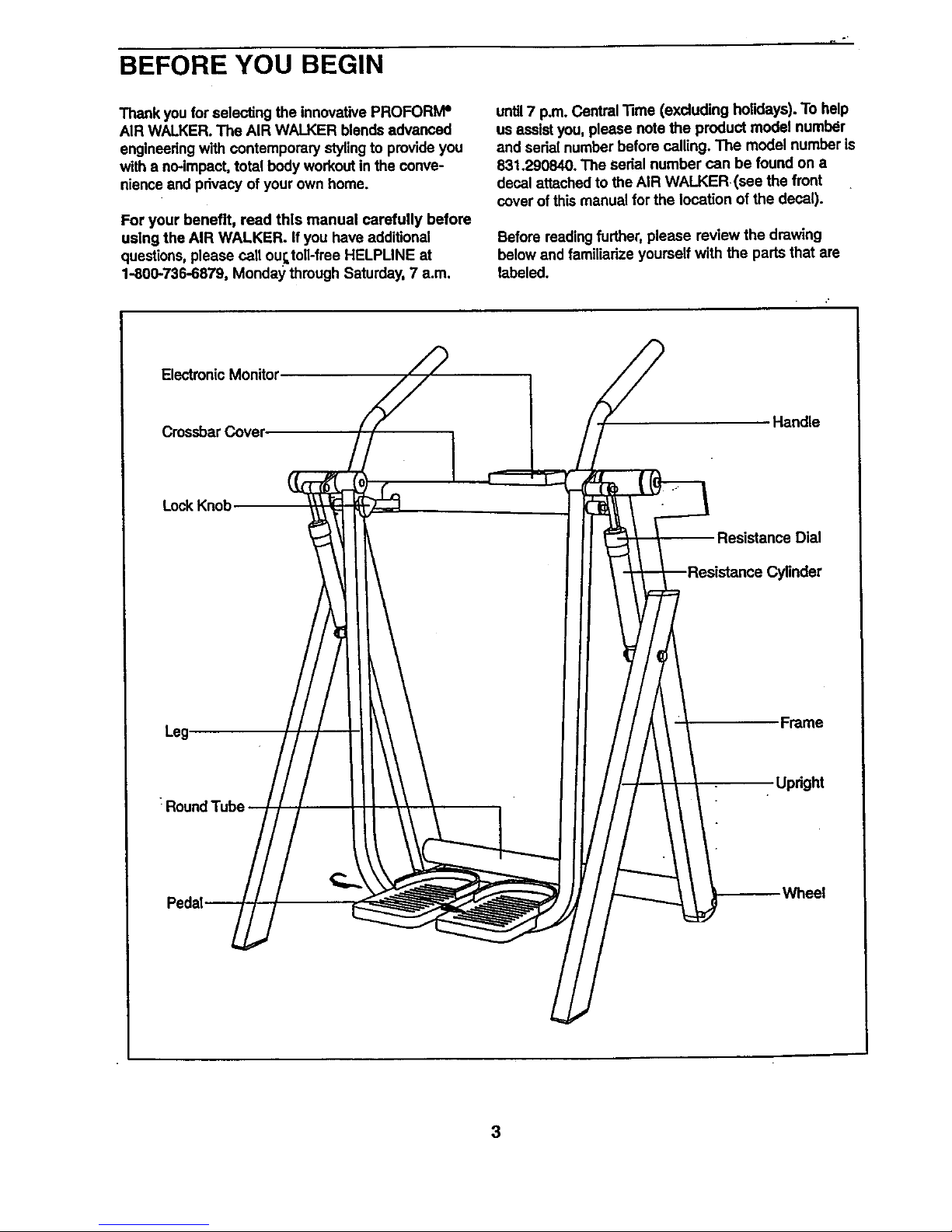
Before reading further, please review the drawing
below and familiarize yourself with the parts that are
labeled.
Electronic Monitor
Crossbar Cover
Handle
Lock Knob
Leg-
Dial
Frame
Updght
Wheel
3
Page 4
ASSEMBLY
Place all parts of the AIR WALKER in a cleared area and remove the packing materials. Do not dispose of the
pacldng materials until assembly Is completed. Read through all assembly steps before you begin.
Assembly requires the Included allen wrench L_ and your own phillips screwdriver (_
and adjustable wrench _.
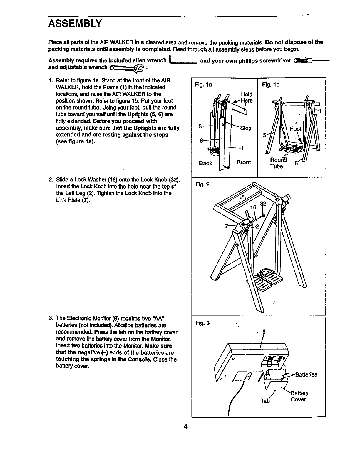
1. Refer to figure la. Stand at the front of the AIR
WALKER, hold the Frame (1) in the Indicated
locations,and raise theAIR WALKER to the
position shown. Refer to figure lb. Put your foot
on the roundtube. Using your foot, pull the round
tube toward yourself untilthe Updghts (5, 6) are
fully extended. Before you proceed with
assembly, make sure that the Uprights are fully
extended and are resting against the stops
(see figure la).
2. Slide a Lock Washer (16) onto the Lock Knob (32).
Insert the Lock Knob intothe hole near the top of
the Left Leg (2). Tighten the Lock Knob into the
LinkPlate (7).
3, The Electmnlc Monitor (9) requires two "AA"
batteries (not Included). Alkaline batteries are
recommended, Press the tab onthe battery cover
and remove the battery cover from the Monitor.
Insert two battedas intothe Monitor. Make sure
that the negative (-) ends of the batteries are
touching the springs in the Console. Close the
battery cover.
Fig. la
5 -- " "_""_"Stop
Back Front
Fig. lb
Roun_d ,/
Tube P
!
Fig. 2
j
Rg. 3
• 9
Ti_b@-b_'Battery
Cover
4
Page 5

4. Connect the Reed Switch _N'ire (12) to the wire on
the Electronic Monitor (9). Feed any excess wire
intothe Crossbar Cover (19), press the Monitor
onto the Crossbar Cover so the Fasteners (48) on
the Monitor snap into the holes in the Crossbar
Cover.
5. Slide one of the Handles (8) onto the Left Leg (2).
Attach the Handle with (_voButton Head Screws
(50) and two 114"Locknuts (23)° Tighten the
Locknuts until the Handle cannot move. The
Handle will be deformed slightly when the
Locknuts are properly tightened.
Attach the other Handle (8) to the Right Leg (3) in
the same manner.
6. The decal shown at the dght is found in the
Indicated location on the AIR WALKER. If the
decal |a m|ss|ng, or if It ts not legible, call our
Customer Service Department, toll-free, to
order a free replacement decal (see
ORDERING REPLACEMENT PARTS on the back
of thLsmanual), Apply the decal in the location
shown.
Make sure that all parts are property tightened before
you use the AIR WALKER.
Fig. 5
5
8
Page 6

HOW TO USE THE AIR WALKER
EXERCISING ON THE AIR WALKER
Make sure that the lock knob is tightened intothe leR
leg and linkplate (see assembly step 2 on page 4).
Adjust the resistance to a high setting, hold the
handles, and step onto the pedals. The proper form
for exercising on the AIR WALKER is similar to the
motion of walking---move one leg forward as you
move the other leg back.
For a full body workout, hold the handles as you walk
and move your arms and legs in motion with the
handles and pedals. To vary the effect of the exercise
on your muscles, bend your legs slightlyinstead of
keeping them straight.
For a lower body workout, rest your hands on the
crossbar cover for balance as you move the pedals.
RESISTANCE ADJUSTMENT
•ELECTRONIC MONITOR MODES
The stmple-to-operste electronic monitor offers
five different modes to provide Instant exercise
feedback. The five modes are described below:
Speed-Displays the number of repetitions you are
performingper minute.
Time--Displays the length of time you have exer-
cised. Note: If you stop exercisingfor ten seconds or
longer, the time mode will pause until you resume.
Distonce--Displays the total number of repetitions
you have completed, up to "999.=The display wiU then
reset to "(7 and continue counting.
Cstorles--Displays the approximate_Dbmber of
Calodes you have bumed. Note: If the resistance is
near the highest or lowest setting, the actual number
of Calodes you have burned will be slightly higher or
lower than the number displayed.
Scen--Displays the speed, time, distance, and calo-
ries modes, for approximately 5 seconds each,
in a repeatingcyde.
DIAGRAM OF THE ELECTRONIC MONITOR
To vary the intensity of your workout,the resistance of
the AIR WALKER can be adjusted. Tochange the
resistance, turn the resistance dials on the resistance
cylinders. There are twelve different resistance levels.
Arrows on the resistance cylinderswill show which
resistance level is selected. Select the same resis-
tance level on both cylinders.
CAUTION: The resistance cylinders become very
hot during use; Allow the resistance cylinders to
cool before touching them. When adjusting the
resistance, touch only the reststance dials.
NES
SPEED TIME
U
I
m
m
m
DIST. CAL. SCAN
Resistance-- 1. LCD display--Displays all modes.
Dial
MODE
i
I
I
ON/RESET i
AUTO OFF
2. Mode indicators---Showwhich mode is selected.
3. Mode button--Selects all modes.
4. On/Reset button--Turns the power on and resets
all modes.
6
Page 7

BA'I-I'ERY_INSTALLATIO N
Before the electronic monitor can be operated, two
"AA"battedee must be installed. If you have not
installed bsttedes, see assembly step 3 on page 4.
OpERATINGTHE ELECTRONIC MONITOR
1. To turn on the power, press the on/reset button or
simply begin exercising on the AIR WALKER. The
entire display will appear for two seconds. The
electmnis monitor willJJlen be ready for operation.
2. Select one of the five modes:
Sc.an mode--Wben the power is tumed on, the
scan mode will be selected automatically. The
scan mode
can also be
selected by
repeatedly
pressing the
mode but-
ton. One
mocle indi-
cator will
show that
the scan
SPEED TIME
DIST. CAL. SCAN
mode 11asbeen selected, and a second mode indi-
cetor will show which mode Is currently displayed.
Speed, time, distance, or calories mode---
These modes can be individually selected by
repeatedly
pressing
the mode
button. The
mode Indi-
cators will
show which
mode has
been
selected.
(Make sure
that the scan mode is not selected.) The modes
will be selected in the following order:,speed, time,
distance, calories, scan.
J SPEED TIME -J
fl ,_-,ooll
LI IJ
DIST. CAL. SCAN
. The monitor has an auto-off feature to turn off
the power. If the pedals are not moved and the
monitor buttons are not pressed for four minutes,
the power will tum off automatically in order to
conserve the batteries.
To reset the LCD display, press the on/reset button.
7
Page 8

STORAGE AND TROUBLE-SHOOTING
Inspect and tighten all parts of the AIR WALKER reg-
ularly. Replace any worn pads immediately.
The AIR WALKER can be cleaned with a soft, damp
cloth. Keep liquids away from the electronic monitor.
Keep the monitor out of direct sunlight or the display
may be damaged. Remove the bsttedes when stodng
the AIR WALKER.
REPLACING THE BATTERIES
If the display,of the electronic monitor becomes dim,
or if the monitor does not function pmpedy, the batter-
ies should be replaced. To replace the battedes, first
liftthe monitor from the crossbar cover (see assembly
step 4 on page 5). Make sure that the reed switch
wire is fully connected to the wire on the monitor. To
replace the batteries, refer to assembly step 3 on
page 4.
HOW TO FOLD THE AIR WALKER FOR STORAGE
When the AIR WALKER is not in use, it can be folded
for storage. To fold the AIR WALKER, first remove the
lock knobfrom the left leg. Next, move to the front of
the AIR WALKER and place one foot on the round
tube. Rrmly grasp the frame with your bands in the
locationsindicated below. While holding the round
tube stationary with your foot, pull the top of the AIR
WALKER toward you untilthe updghts fold against
the frame. Place the AIR WALKER In a Iocetlon
where it cannot fall.
Y
LOCK
\ Knob
ir] i
Back
Front
Hand
Fl'_31e
Round
8
Page 9

CONDITIONING GUIDELINES
The following guidelines will help you to plan your
exemise program. Remember that proper nutrition and
adequate rest are essential for successful results.
EXERCISE INTENSITY
Whether your goal is to burn fat or strengthen your
cardiovascular system, the key to achieving the
desired results is to exercise with the proper intensity.
The proper intensity level can be found by using your
heart rate as a guide. The chart below shows recom-
mended heart rates for fat burning, maximum fat bum-
ing, and cardiovascular (aerobic) exercise.
BPM
HEART RATE TRAINING ZONES
II l= Igl mm= =11
t llllllllllmlllEI
To find the proper hi_adrate for you, first.find your age
near the bottom of the chart (ages are rounded off to
the nearest ten years). Next, look above your age and
find the three numbers in light gray boxes. The three
numbers are your "training zone." The lowest number
is the recommended heart rate for fat bumlng; the
middle number isthe recommended heart rate for
maximum fat burning; the highest number is the rec-
ommended heart rate for aerobic exercise.
Fat Burning
To bum fat effectively, you must exercise at a relative-
ly low intensity level for a sustained period of time.
During the first few minutes of exercise, your body
uses easily accessible carbohydrate calodes for ener-
gy. Only after the first few minutes of exercise does
your body begin to use stored fatcalodes for energy.. If
your goal is to burn fat, adjust your pace until your
heart rate is near the lowest number in your training
zone e_ y:'."'_::erclse.It may also be helpful to set the
dialson the resistance cylinders at level 1, 2, 3, or 4.
For maximum fat burning, adjust your pace until your
heart rate is near the middle number in your training
zone as you exercise.
Aerobic Exercise
Ifyour goal is to strengthen your cardiovascular sys-
tem, your exercise must be =aerobic." Aerobic exercise
is activity that requires large amounts of oxygen for
prolonged periods of time. This increases the demand
on the heart to pump blood to the muscles, and on the
lungsto oxygenate the blood. For aerobic exercise,
adjust your pace untilyour heart rate is near the high-
est number in your trainingzone. It may also be help-
ful to set the dials on the resistance cylinders at level
5, 6,7, or 8.
Strength Training
To strengthenand tone your muscles, you must exer-
ciseyour muscles at a moderate to high peCcentageof
theircapacity. Set the dials on the resistance cylinders
at level 9, 10, 11, or 12.
HOW TO MEASURE YOUR HEART RATE
To measure your heart rate, first exemise for at least
four minutes.
Then, stop
exercising and
place two fin-
gers on your
wdst as
shown. Take a
six-second
heartbeat
count, and
multiply the
result by 10 to
find your heart
rate. For example, ifyour six-sesond heartbeat count
is 14, your heart rate is 140 beats per minute. (A six-
secorfdcount is used because your heart rate will
drop rapidly when you stop exercising.)
Adjust the intensity of your exemise until your heart
rate is at the desired level. You can adjust the intensity
of your exercise by adjusting the resistance or by
changing your pace.
9
Page 10

WORKOUT GUIDELINES
Each workout should include the following three pads:
A warm-up, lasting 5 to 10 minutes. Begin with slow,
controlled stretches, and progress to more rhythmic
stretches to increase the body tempsmture, heart rate,
and circulationin preparation for strenuous exercise.
Train|ng zone exercise, consisting of 20 to 30 min-
utes of exercising with your heart rate in your training
zone.
A cool-down, with 5 to 10 minutes of stretching.
Thorough stretching helps to offset problems caused
I*
when you stop exercising suddenly. Stretching for
increased flexibility is also most effective after exercis-
ing. A proper cool-down should leave you relaxed and
comfortablytired.
EXERCISE FREQUENCY
To maintain or improve your condition, plan three
workouts each week, with at least one day of rest
between workouts. After a few months of regular exer-
cise, you may complete up to five workouts each
week, if desired.
Remember,the keyto successis make exercisea
regularandenjoyablepartofyoureverydaylife.
PART LIST--Model No. 831.290840
a/ ljo
Key Part Key Part
"No; Qty. No. Description No. Oty. No. DescripUon
1 1 NSP Frame 27 1 136612 RightPedai Cover
2 1 136816 Left Leg 28 1 136600 Left Pedal Cover
3 1 136818 Right Leg 29 6 013300 #8 x 3/4" Screw
4 1 137686 Rocker Arm 30 2 130953 Resistance Cylinder
5 1 137827 Left Upright 31 2 133072 Tree Fastener
6 1 136822 Right Updght 32 1 136861 Lock Knob
7 1 136829 Link Plate 33 2 119994 Button Head Screw
6 2 136830 Handle 34"- 6 123116 Frame Endcap
9 1 130165 Electronic Monitor 35 1 127896 RockerArm Bolt
10 1 016028 Adhesive Tool Clip 36 2 103903 Small Axle Cap
11 1 107094 Magnet 37 2 013359 Hex Head Screw
12 1 131101 Reed Switch Wire ...._38 3 100553 1/2_Nylon Locknut
13 2 137683 UnkArm 39 2 014080 1/2" RatWesher
14 2 137685 UnkArrn Joint : 40 2 013601 Wheel Screw
15 4 136597 Small Bronze Bushing 41 2 012149 3/8" Nylon Locknut
16 1 110468 Look Washer 42 2 052014 Wheel
17 4 136598 Large Bronze Bushing 43 2 014132 3/8" Rat Washer
18 1 131833 "D" Bushing 44 1 100151 Large Axle Cap
19 1 136599 Crossbar Cover 45 2 126650 Rubber Foot
20 1 136601 Left Leg Cover 46 8 013162 #6 x 1/2" Screw
21 1 136602 Right Leg Cover 47 2 136837 Handle Grip
22 2 136603 Axle Cover 45 2 127597 Double Tree Fastener
23 4 012139 1/4" Locknut 49 1 136967 Star Washer
24 1 136605 Left Axle Spacer 50 4 122794 Button H_ad Screw
25 1 136606 Right Axle Spacer 51 2 105496 3/8" Push Nut
26 2 129110 RookerArrn Spacer # 1 137741 User's Manual
R0397B
Note: "_ refers to a non-illustrated part. Specifications are subject to change withoutnotice. See the back cover
of this manual for information about ordedng replacement parts.
10
Page 11

EXPLODED DRAWING--Model No. 831.290840
47
4\ 34
.v..
19..
8,
12.,
a
11o,
22
17
.°°.,,_50
3O
14 51
8
\
33
RO397B
37
39
4O
14
15
7
2O
21
31
• 28
15
15
44
11
Page 12

S ARS
Model No. 831.290840
QUESTIONS?
If you find that:
• you need help assembling or
operating the PROFORMeAIR
WALKER :_
• a part is _tlssing
• or you need to schedule repair
service
call our toll-free HELPLINE
1-800-736-6879
Monday-Saturday, 7 am-7 pm
Central Time (excluding holidays)
REPLACEMENT
PARTS
If parts become wom and need to
be replaced, call the following
toll-free number
1-800-FON-PART
(1-800-366-7278)
The model number and serial number of your PROFORMP AIR
WALKER are listed on a decal attached to the frame. See the front
cover of this manual to find the location of the decal.
All replacement parts are available for immediate purchase or
special order when you visit your nearest SEARS Sen/ice Center.
To request service or to order parts by telephone, call the toll-free
numbers listed at the left.
When requesting help or service, or ordedng pads, please be pre-
pared to provide the following information:
• The NAME OF THE PRODUCT (PROFORM" AIR WALKER)
• The MODEL NUMBER OF THE PRODUCT (831.290840)
• The PART NUMBER OF THE PART (see page l_of this manual)
_. The DESCRIPTION OFTHE PART (see page 10 of this manual)
I FULL 90 DAY WARRANTY I
For 90 days from the date of purchase, tf failure occurs due to defect in material or workmanship In this
AIR WALKER EXERCISER, contact the nearest SEARS Sewice Center throughoutthe United States
and SEARS will repair or replace the AIRWALKER EXERCISER, free of charge.
Thiswarrantydoesnot applywhentheAIR WALKEREXERCISERis usedcommerciallyor for rentalpur-
poses.
This warranty gives you specific legal dghts, and you may also have other dghtsWhichvary from state.
to state.
SEARS; ROEBUCK AND CO., DEPT. 817WA, HOFFMAN ESTATES, IL 60179
Part No. 137741 G00907AC R0397B Pdnted in USA© 1997 Sears, Roebuck and Co.
 Loading...