

Page 1
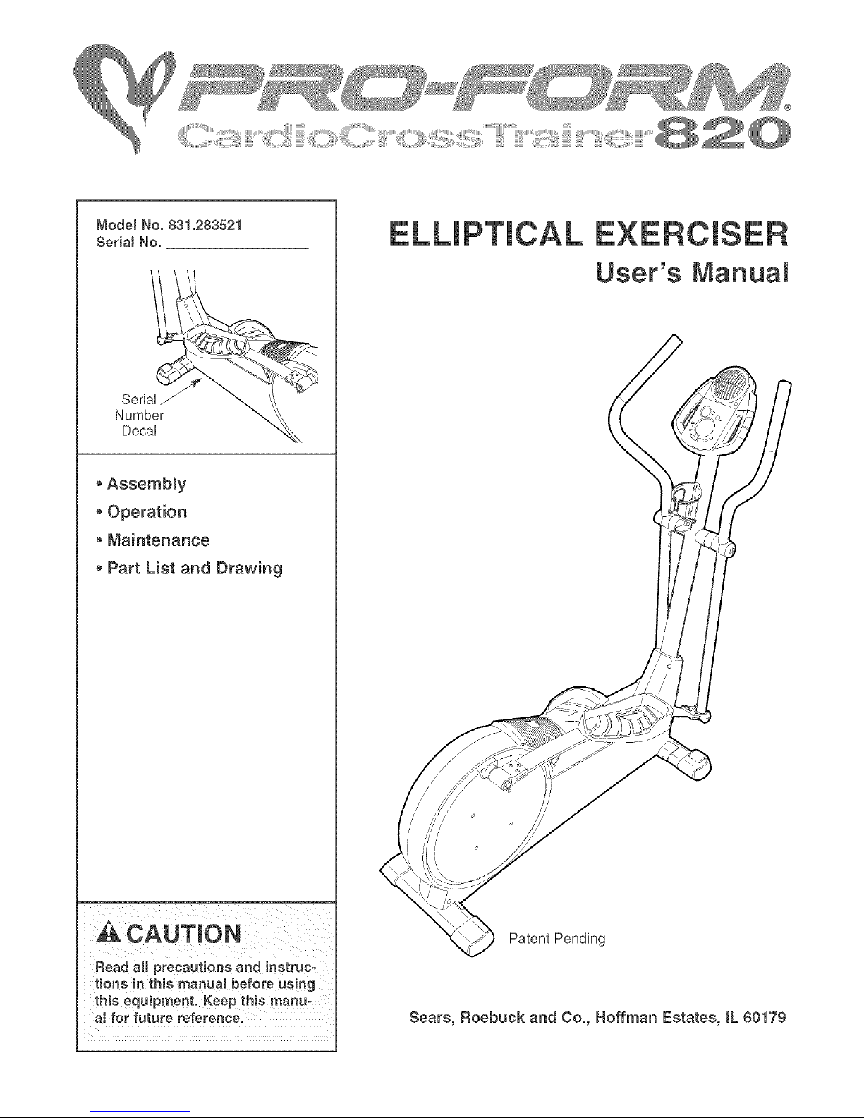
Mode! No. 831.283521
SedaJ No.
SeriaUJ
Number
DecaU
o Assembly
Operation
Maintenance
Part List and Drawing
User's Manual
Read aH precautions and instruc-
tions in this manual before using
this equipment. Keep this manu-
al for future reference.
Patent Pending
Sears, Roebuck and Co., Roffman Estates, IL 60179
Page 2
TABLE OF CONTENTS
iMPORTANT PRECAUTIONS ................................................................ 3
BEFORE YOU BEGIN ...................................................................... 4
ASSEMBLY ............................................................................... 5
HOW TO USE THE ELLiPTiCAL CROSSTRAINER ............................................... 9
MAINTENANCE AND TROUBLESHOOTING ................................................... 20
CONDiTiONiNG GUiDELiNES ............................................................... 21
PART LiST .............................................................................. 22
EXPLODED DRAWING .................................................................... 23
HOW TO ORDER REPLACEMENT PARTS ............................................. Back Cover
FULL 90 DAY WARRANTY .......................................................... Back Cover
2
Page 3
iMPORTANT PRECAUTIONS
A_ WARN ING: To reduce the riskofserious injury, read the followingimportantprecau-
tions before using the elliptical croeetrainer.
t. Read all instructions in this manual before
using the elliptical croeetrainer.
2. it is the responsibility of the owner to ensure
that all users of the elliptical crosstrainer are
adequateJy informed of aI[ precautions.
3. The elliptical crosstrainer is intended for
home use only. Do not use the elliptical
croeetrainer in a commercial rental, or insti-
tutional setting.
4. Place the elliptical croeetrainer on a level
surface, with a mat beneath it to protect the
floor or carpet. Keep the eiJiptica[ croeetrain-
er indoors, away from moisture and dust.
5. inspect and properly tighten eli parts regu-
larly. Replace any worn parts immed[ate[y.
6. Keep children under 12 and pets away from
the elliptical croeetrainer at a[[ times.
7. The elliptical crosstrainer should not be used
by persons weighing more than 250 pounds.
8. Wear appropriate exercise clothes when
using the elliptical crosetrainer. Always wear
athletic shoes for foot protection whiJe exer-
cising.
9. Hold the handgrip pulse sensor or the han-
dlebars when mounting, dismounting, or
using the elliptica[ croeetrainer.
10. The pulse sensor is not a medical device.
Various factors may affect the accuracy ot
heart rate readings. The pulse sensor is
intended onty as an exercise aid in determin-
ing heart rate trends in general.
11. Keep your back straight when using the ellipo
t[ca[ crosetra[ner; do not arch your back.
12. If you feel pain or dizziness at any time
while exercising, stop immediately and cool
down.
13. When you stop exercising, allow the pedals
to eJow[y come to a stop.
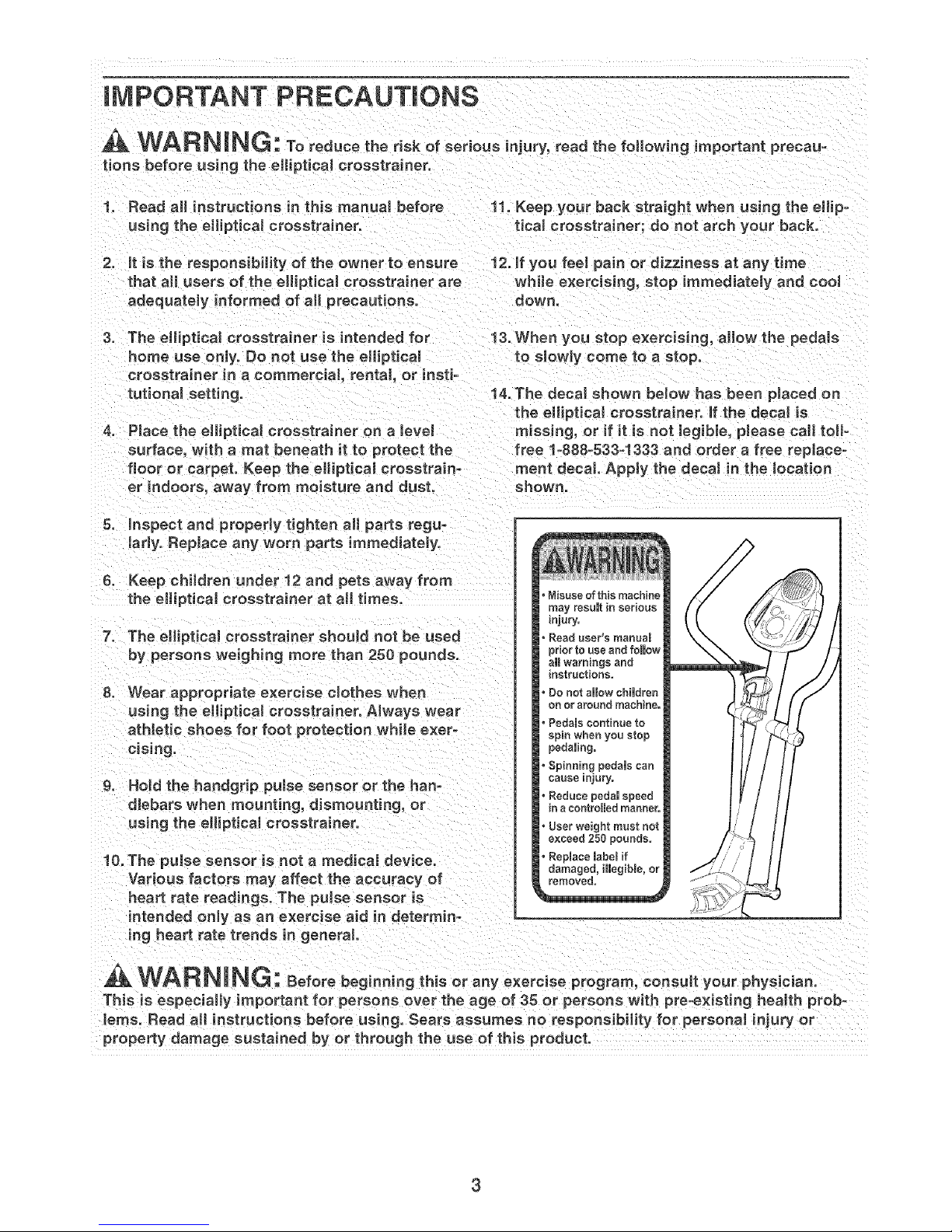
14. The decal shown be[ow has been pieced on
the e[[i ptica[ crosetrainer, if the decal is
missing, or if it is not legible, please ca[[ toil-
free 1-888-533-1333 and order a free repiaceo
ment decal Apply the decal in the location
shown.
Misuse of this machine
may resumtm serious
mjury,
Read user's manual
prior to useandfo[mow
ai[ warnings and
instructions,
Do not show chimdren
on or around machine,
PedaBs continue to
spin when you stop
pedaling.
Spinning pedamscan
causeinjury,
Reduce pedam speed
in aeontroBed manner,
User weight must not
exceed 250 pounds,
ReplacelebeBif
damaged, iliegibRe,or
WARNING: Beforebeginningthieoranye.erc,eeprogram,consu,yourphye c an.
This is especially important for persons over the age of35 or persons with pre-existing health prob-
lems. Read all instructions before using. Sears assumes no responsibility for personal injury or
property damage sustained by or through the use of this product.
3
Page 4
BEFORE YOU BEGIN
CongratuUations for sebcting the new PROFORM ®
820 CARDUO CROSSTRAUNER, The PROFORM ®820
is an incrediMy smooth exerciser that moves your feet
in a naturaUeHiptbaUpath, minimizing the impact on
your knees and anHes, And the unique PROFORM ®
820 features adjustabb resistance and a state°of-the°
art consob to heUpyou get the most from your
exercise,
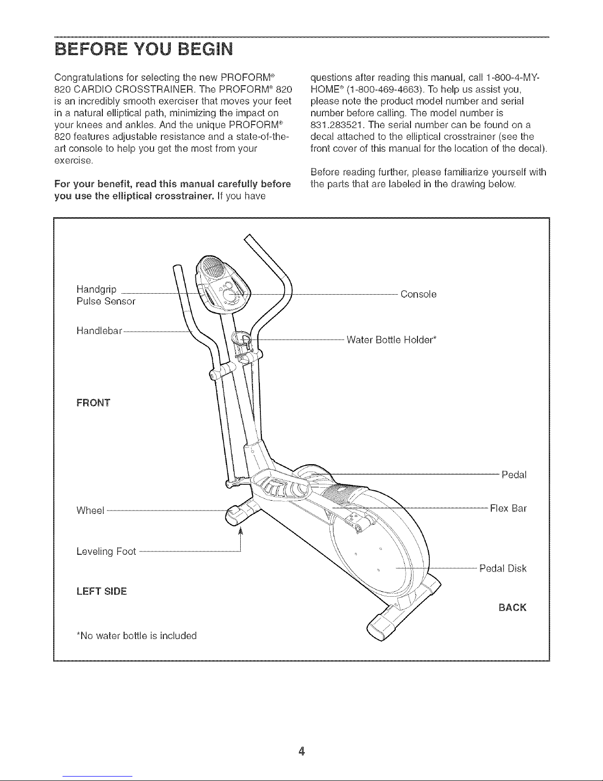
For your benefit, read this manual carefully before
you use the elliptical crosstrainer, if you have
Handgrip
Pulse Sensor
Handiebau
questions after reading this manual, call 1°800°4°MYo
HOME ®(1o800o469o4663), To help us assist you,
please note the product model number and serial
number before calling, The model number is
831,283521, The serial number can be found on a
decal attached to the elliptical crosstrainer (see the
front cover of this manual for the location of the decal),
Before reading further, please familiarize yourself with
the parts that are labeled in the drawing below,
Console
Water Bottle Holder*
FRONT
Wheel
Leveling Foot
LEFT SIDE
*No water bottle is included
Pedal
Flex Bar
Pedal Disk
BACK
4
Page 5
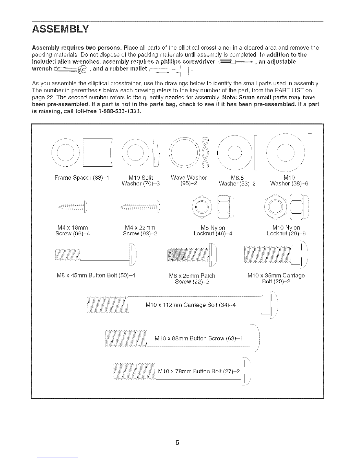
AssemMy requires two persons. PHaceaHHparts of the eHHpticaHcrosstrainer in a cHeared area and remove the
packing materiaHs, Do not dispose of the packing materiaHs until assembHy is compHeted, In addition to the
included allen wrenches, assembly requires a phillips screwdriver _ _, an adjustable
wrench __ and a rubber mattet .... ' '
%c--
As you assembHe the eHHpticaHcrosstrainer, use the drawings bellow to identify the smaHHparts used in assembHy,
The number in parenthesis bellow each drawing refers to the key number of the part, from the PART LHSTon
page 22. The second number refers to the quantity needed for assembHy. Note: Some small parts may have
been pre-assemMed, if a part is not in the parts bag, check to see if it has been pre-assemMed, if a part
is missing, call toil-free 1-888-533-1333.
MIO SpHit Wave Washer M8,5
Washer (70)-3 (95)-2 Washer (53)-2
iJ
M4 x 16mm
Screw (66)-4
M4 x 22mm
Screw (93)-2
x
M8 x 45mm Button BoHt(50)-4 M8 x 25mm Patch
Screw (22)-2
/
/
\
"•,\ /_ j'
MIO
Washer(38)-6
MIO NyHon
Locknut (29)-6
MIO x 35mm Carriage
i J
MIO x 78mm Button BoHt(27)-2 i i
Page 6
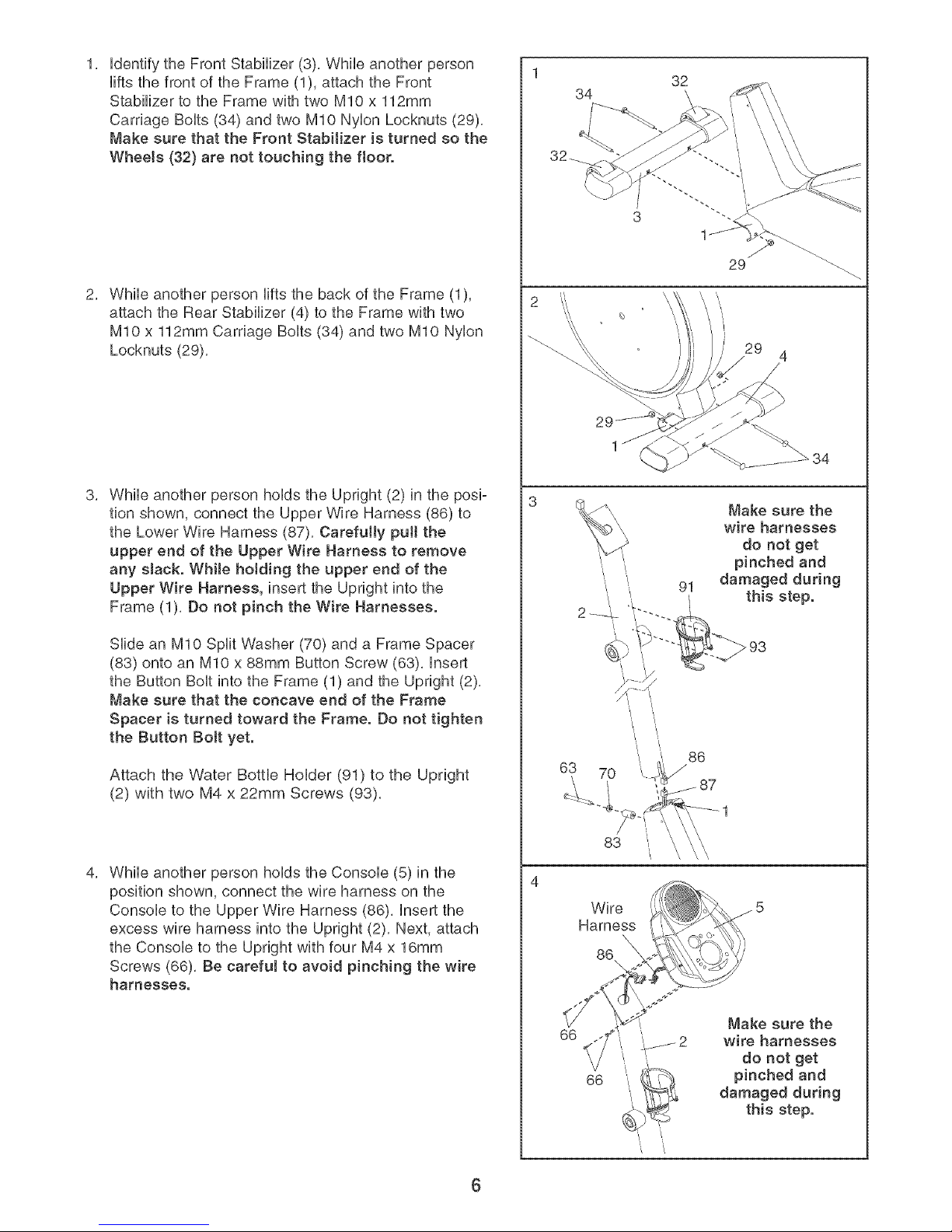
IdentifytheFrontStabilizer(3),Whileanotherperson
liftsthefrontoftheFrame(1),attachtheFront
StabilizertotheFramewithtwoMIOx112mm
CarnageBolts(34)andtwoMIONylonLocknuts(29),
MakesurethattheFrontStabilizeristurnedsothe
Wheels(32) are not touching the floor.
29
/
While another person lifts the back of the Frame (1),
attach the Rear Stabilizer (4) to the Frame with two
MIO x 112mm Carnage Bolts (34) and two MIO Nylon
Locknuts (29),
While another person holds the Upnght (2) in the posi-
tion shown, connect the Upper Wire Harness (86) to
the Lower Wire Harness (87), Carefully pull the
upper end of the Upper Wire Harness to remove
any sJack. While hoJding the upper end of the
Upper Wire Harness, insert the Upnght into the
Frame (1), Do not pinch the Wire Harnesses.
Slide an MIO Split Washer (70) and a Frame Spacer
(83) onto an MIO x 88mm Button Screw (63), Insert
the Button Bolt into the Frame (1) and the Upright (2),
Make sure that the concave end of the Frame
Spacer is turned toward the Frame. Do not tighten
the Button Bolt yet.
Attach the Water Bottle Holder (91) to the Upright
(2) with two M4 x 22mm Screws (93).
2
\
29
4
/
Make sure the
wire harnesses
do not get
pinched and
damaged during
91
this step.
793
/,
86
/
1
While another person holds the Console (5) in the
position shown, connect the wire harness on the
Console to the Upper Wire Harness (86), Insert the
excess wire harness into the Upright (2), Next, attach
the Console to the Upright with four M4 x 16mm
Screws (66), Be careful to avoid pinching the wire
harnesses.
83
4
Wire
Harness
86
66
Make sure the
wire harnesses
do not get
66
pinched and
damaged during
this step.
/ /,
"i '/
6
Page 7
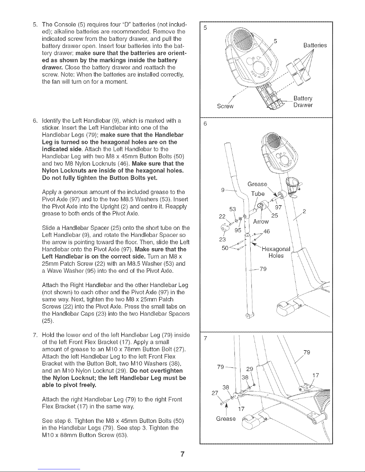
The ConsoUe (5) requires four "D" batteries (not incUud-
5, 5
ed); aHkaHnebatteries are recommended, Remove the
indicated screw from the battery drawer, and puHHthe
battery drawer open, Hnsert four batteries into the bat-
tery drawer; make sure that the batteries are orient-
ed as shown by the markings inside the battery
drawer. CHosethe battery drawer and reattach the
screw, Note: When the batteries are instaHHedcorrectly,
the fan wHHturn on for a moment,
Hdentifythe Left HandHebar (9), which is marked with a
sticker, Hnsertthe Left HandHebar into one of the
HandHebar Legs (79); make sure that the Handlebar
Leg is turned so the hexagonaJ holes are on the
indicated side, Attach the Left HandHebar to the
HandHebar Leg with two M8 x 45mm Button BoHts(50)
and two M8 NyHon Locknuts (46), Make sure that the
NyJon Locknuts are inside of the he×agonat holes.
Do not futty tighten the Button Bolts yet.
Apply a generous amount of the included grease to the
Pivot Axle (97) and to the two M8,5 Washers (53), insert
the Pivot Axle into the Upright (2) and centre it, Reappiy
grease to both ends of the Pivot Axle,
Slide a Handlebar Spacer (25) onto the short tube on the
Left Handlebar (9), and rotate the Handlebar Spacer so
the arrow is pointing toward the floor, Then, slide the Left
Handlebar onto the Pivot Axle (97), Make sure that the
Left Handlebar is on the correct side. Turn an M8 x
25mm Patch Screw (22) with an M8,5 Washer (53) and
a Wave Washer (95) into the end of the Pivot AxHe,
/
/
Screw
Grease
Tube
t
53 / !7 _'i
22 25
krrow
I
-p_79
5
Batteries
Battery
Drawer
Attach the Right HandHebarand the other HandHebar Leg
(not shown) to each other and the Pivot AxHe(97) in the
same way, Next, tighten the two M8 x 25mm Patch
Screws (22) into the Pivot AxHe,Press the smaHHtabs on
the HandHebar Caps (23) into the two HandHebarSpacers
(25),
HoHdthe Howerend of the HeftHandHebar Leg (79) inside
of the HeftFront FHexBracket (17), AppHya smaHH
amount of grease to an MIO x 78mm Button BoHt(27),
Attach the HeftHandHebar Leg to the HeftFront FHex
Bracket with the Button BoHt,two MIO Washers (38),
and an MIO NyHonLocknut (29), Do not overtighten
the NyJon Locknut; the teft Handlebar Leg must be
able to pivot freely.
Attach the right HandHebar Leg (79) to the right Front
FHexBracket (17) in the same way,
See step 6, Tighten the M8 x 45mm Button BoHts(50)
in the HandHebar Legs (79), See step 3, Tighten the
MIO x 88mm Button Screw (63),
7
27
Grease
38
I
17
!
17
Page 8
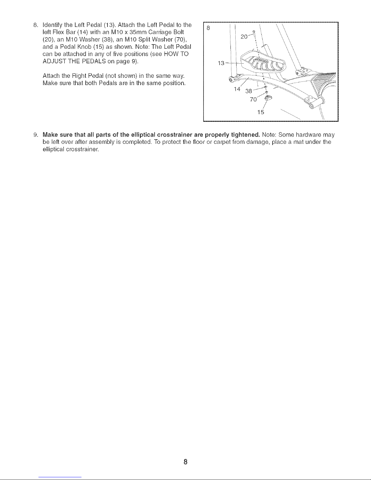
UdentifytheLeftPedaU(13),AttachtheLeftPedaUtothe
UeftFUexBar(14)withanMIOx35mmCarriageBoUt
(20),anMIOWasher(38),anMIOSplitWasher(70),
andaPedaUKnob(15)asshown,Note:TheLeftPedaU
canbeattachedinanyoffivepositions(seeHOWTO
ADJUSTTHEPEDALSonpage9),
AttachtheRightPedal(notshown)inthesameway,
MakesurethatbothPedalsareinthesameposition,
9, Makesurethata[[partsoftheellipticalcrosstrainerareproperlytightened.Note:Somehardwaremay
beleftoverafterassemblyiscompleted,Toprotectthefloororcarpetfromdamage,placeamatunderthe
ellipticalcrosstrainer,
8
Page 9

HOW TO USE THE ELLiPTiCAL CF{OSSTRAJNER
HOW TO ADJUST THE PEDALS
The motion of the
pedaUs is deter- BoUt Fbx Bar
mined by their
positions on the
flex bars, There
are five positions,
To adjust each
pedaU,first bosen
the knob beneath PedaU
the pedak Next, Knob
push the bout
upward, slide the
pedaUforward or backward to the desired position, and
then retighten the knob, Make sure that both pedab
are in the same position,
HOW TO EXERCISE ON THE ELLIPTICAL
CROSSTRAINER
To mount the eHiptbaUcrosstrainer, hoUdthe handgrip
puUsesensor and step onto the pedaUthat is in the bw-
est position, Then, step onto the other pedak Push the
pedaUs until they begin to move with a continuous
motion, Note: The peda! disks can turn in either
direction. It is recommended that you move the
pedaJ disks in the direction shown by the arrow
below; however, for variety, you can turn the pedal
disks in the opposite direction.
To dismount the elliptical crosstrainer, wait until the
pedals come to a complete stop, Note: The eHipticaJ
crosstrainer does not have a free whee!; the ped-
als will continue to move until the flywheel stops.
When the pedals are stationary, step off the highest
pedal first, Then, step off the lowest pedal,
HOW TO USE THE HANDLEBARS
The handlebars are
designed to add
upper-body exer-
cise to your work-
outs, Push and pull
the handlebars as
you exercise to
work your arms,
shoulders, and
back,
To exercise only
your lower body,
hold the handgrip
pulse sensor as
you exercise,
Handlebars
Handgrip
Pulse
ensor
,& CAUTION: BeforeusingtheeHipti-
caJ crosstrainer, read the following precau-
tions.
Handgrip
Pulse Sensor
Pedals
,,Always hold the handgdp puJse sensor or the
handJebars when mounting, dismounting, or
using the elliptical cross, trainer.
,,When you stop exercising, allow the pedals to
slowly come to a stop.
,,The pulse sensor is not a medical device.
Various factors may affect the accuracy of
heart rate readings. The putse sensor is
intended only as an exercise aid in determin-
ing heart rate trends in general
9
Page 10

Display Buttons
HeartRate Control SmartPrograms
AerobicPlateau 1 3 WeightLoss Progressive
Button
On/Reset Button
Resistance Buttons
FEATURES OF THE CONSOLE
The advanced console offers a selection of features
designed to make your workouts more enjoyable and
effective, When the manual mode of the console is
selected, the resistance of the pedals can be changed
with the touch of a button, As you pedal, the console
will provide continuous exercise feedback, You can
even measure your heart rate using the built-in hand-
grip pulse sensor,
The console also offers four Smart programs, Each pro-
gram automatically changes the resistance of the ped-
als and prompts you to increase or decrease your pace
as it guides you through an effective workout,
in addition, the console features two Heart Rate pro-
grams that change the resistance of the pedals and
prompt you to vary your pace to keep your heart rate
near a target heart rate as you exercise,
The console also features iFIT,eom interactive technol-
ogy, Having iFIT,com technology is like having a per-
sonal trainer in your home, Using a stereo audio cable
(available at electronics stores), you can connect the
elliptical crosstrainer to your home stereo, portable
stereo, computer, or VCR and play special iFIT,com CD
and video programs (iFIT,com CDs and videocassettes
are available separately), iFIT,com CD and video pro-
grams automatically control the resistance of the ped-
als and prompt you to vary your pace as a personal
trainer coaches you through every step of your work-
out, High-energy music provides added motivation, To
purchase iFIT.com ODe and videocaesettes, call
toll-free 1-888-533-1333.
With the elliptical crosstrainer connected to your com-
puter, you can also go to our Web site at www, iFIT,com
and access programs directly from the internet,
Explore wwwJFIToeom for more information.
To use the manual mode of the consoJe, see page
11, To use a Smart program, see page 13, To use a
Heart Rate program, see page 14, To use an
iFIT.eom CD or videocaesette, see page 18, To use
a program directly from our Web site, see page 19,
10
Page 11

HOWTO USE THE MANUAL MODE
Turn on the console.
Note: The consob requires four 1,5V "D" batteries
(see assembly step 5 on page 7),
To turn on the consob, press the On/Reset button
or begin pedaling, (See the drawing on page 11 to
identify the On/Reset button,)
Select the manuaJ mode.
Each time the console is
turned on, the manual
mode wiii be selected, if a
program has been select-
ed, select the manual
mode by pressing the
Program button repeated°
ly until the letters RPM
appear in the small display,
Begin pedaling and change the resistance of
the pedals as desired.
As you pedal, change the resistance of the ped-
als by pressing the + and - buttons below the
large display, There are ten resistance levels--
level 10 is the most challenging, Note: After the
buttons are pressed, it will take a few seconds for
the resistance to reach the selected setting,
Follow your progress with small display and
the large display.
The small display wiii
show your pedaling pace,
in revolutions per minute
(RPM), The indicator bar
in the small display will
increase or decrease in
length as you increase or
decrease your pedaling
pace,
The upper sec-
tion of the
large display
wiil show the
distance you
have pedaled
and the numbers of calories and fat calories you
have burned (see FAT BURNING on page 21 for
an explanation of fat calories), The display will
change from one number to the next every few
indicator Bar
seconds, if you use the handgrip pulse sensor,
the display wiii also show your heart rate (see
step 5 on page 12),
To view only the distance
you have pedaled or the
number of calories or fat
calories you have burned,
press the upper button on
the left side of the large
display until only the word
DISTANCE, CALORIES, or
FAT CALORIES appears in the upper section of
the large display. Make sure that the word SCAN
does not appear, To again view the distance you
have pedaled and the numbers of calories and
fat calories you have burned, press the upper
button until the word SCAN reappears,
The center of
the large display
will show the
elapsed time and
your current pace '.SPEE_
(pace is shown in
minutes per mile), The display will change from
one number to the other every few seconds,
Note: When a program is selected (except for the
SelfSelect program), the display wiii show the
time remaining in the program instead of the
elapsed time,
To view only the elapsed time or your pace, press
the center button on the left side of the large dis-
play until only the word TiME or PACE appears,
Make sure that the word SCAN does not appear,
To view both the elapsed time and your pace,
press the center button until the word SCAN
reappears,
The Jower sec-
tion of the large
display wiii show ,,,sP_E_
your pedaling
speed and the
resistance level,
The display will change from one number to the
other every few seconds,
To view only your pedaling speed or the resis-
tance level, press the lower button on the left
side of the large display until only the word
SPEED or RESISTANCE appears. Make sure
that the word SCAN does not appear, To view
both your pedaling speed and the resistance
level, press the lower button until the word SCAN
reappears,
11
Page 12

To reset the dispUays, press the On/Reset button,
Note: The con-
sole can show
speed and dis- _F'EED
tance in either
miles or kilo-
meters. The bt-
ters MPH or KM/H wHUappear in the bwer section
of the UargedispUayto show which system of mea-
surement is sebcted, To change the system of
measurement, hoUddown the On/Reset button for
about six seconds, Note: When the button is heUd
down, the fan wHUturn on for a moment, When the
batteries are repUaced,it may be necessary to res-
ebct the desired system of measurement,
Measure your heart rate if desired.
If there are
thin sheets of
plastic on the
metal contacts
on the hand-
grips, peel off
the plastic. To
use the hand-
grip puUsesen-
sor, hoUdthe handgrips with your paUms resting
against the metal contacts, Avoid moving your
hands. When your pulse is detected, the heart-
shaped indicator in the large display will flash
each time your heart beats, After a moment, two
dashes (- -) will appear and then your heart rate
will be shown,
For the most accurate heart rate reading, continue
to hold the handgrips for about 30 seconds, Note:
When you first hold the handgrips, the large dis-
play will show your heart rate continuously for 30
seconds, The display will then show your heart
rate along with other feedback modes,
Turn on the fan if desired.
To turn on the
fan at low speed,
press the fan
button, To turn
on the fan at
high speed,
press the fan
button a second
time, To turn off
the fan, press the fan button a third time, Note: if
the fan is turned on but the pedals are not moved
for thirty seconds, the fan will automatically turn
off to conserve the batteries,
Rotate the thumb wheel on the right side of the
console to pivot the fan to the desired angle,
When you are finished exercising, the consote
wilt automatically turn off.
if the pedals are not moved for a few seconds,
the displays wiii pause and the time wiii flash in
the large display,
if the pedals are not moved and the console but-
tons are not pressed for a few minutes, the con-
sob will turn off to conserve the batteries,
12
Page 13

HOW TOUSE A SMART PROGRAM
Each Smart program wiii automatically change the
resistance of the pedals and prompt you to increase or
decrease your pace as it guides you through an effec-
tive workout, Programs 3 and 4 are weight loss pro-
grams, program 5 is an aerobic program, and program
6 is a high-performance interval-training program,
Follow the steps below to use a Smart program,
Turn on the console.
See step 1 on page 11.
Select one of the Smart programs.
Each time the console is
turned on, the manual
mode wiii be selected, To
select a Smart program,
press the Program button
repeatedly until the num-
ber 3, 4, 5, or 6 appears in
the small display,
Begin pedaling to start the program.
To start the program, simply begin pedaling, Each
Smart program consists of 20 or 30 one-minute
periods, One resistance level and one target pace
are programmed for each period, (The same
resistance level and/or target pace may be pro-
grammed for two or more consecutive periods,)
The target pace
for the current
period wiii be
shown by the
arrows in the
small display, To
pedal at the target
pace, simply
increase or decrease your pace until there is one
arrow pointing to each segment of the indicator
bar (see the drawing above), At the end of each
period, the number of arrows wiii change if a dif-
ferent target pace is programmed for the next
period, When the number of arrows changes,
change your pace until there is one arrow point-
ing to each segment of the indicator bar,
Important: The target pace is intended only to
provide a goa!. Your actual pace may be slow-
er than the target pace, especially during the
first few months of your exercise program.
Make sure to pedal at a pace that is comfort-
able for you.
During the program, the center of the large dis-
play wiii show the time remaining in the program,
if you stop pedaling for a few seconds, the dis-
plays wiii pause and the time wiii flash, if you
continue pedaling after the program is completed,
the displays will continue to show exercise feed-
back,
Fottow your progress with the large display.
See step 4 on page 11,
Measure your heart rate if desired.
At the end of each period of the program, the
resistance of the pedals wiii automatically change
if a different resistance level is programmed for
the next period, Note: if the resistance level is too
high or too low, you can change it by pressing the
+ and - buttons below the large display, However,
when the current period is completed, the resis-
tance of the pedals will automatically change if a
different resistance level is programmed for the
next period,
See step 5 on page 12,
Turn on the fan if desired.
See step 6 on page 12,
When you are finished exercising, the console
wilt automatically turn off.
See step 7 on page 12,
13
Page 14

HOW TO USE A HEART RATE PROGRAM
Heart Rate program 1 is designed to keep your heart
rate between 65% and 85% of your maximum heart
rate during your workout, ('Your maximum heart rate is
estimated by subtracting your age from 220, For
exampUe, if you are 25 years oUd,your maximum heart
rate is 195 beats per minute,) Heart Rate program 2 is
designed to keep your heart rate near a target heart
rate that you seUect,
Follow the steps below to use a Heart Rate program,
Turn on the console.
See step 1 on page 11,
Select one of the Heart Rate programs.
to operate properly, Each time you hold the
handgrips, keep your hands on the metaJ con-
tacts for at teast 30 seconds. Note: When you
are not holding the handgrips, the letters PLS will
appear in the large display instead of your heart
rate,
Begin pedaling to start the program.
To start the program, simply begin pedaling,
Program 1 consists of 20 one-minute periods,
One resistance level and one target heart rate are
programmed for each period, (The same resis-
tance level and/or target heart rate may be pro-
grammed for two or more consecutive periods,)
Program 2 is sixty minutes long (you may choose
to use only part of the program), The same resis-
tance level and target heart rate are programmed
for the entire program,
Each time the consoUe is
turned on, the manuaU
mode wHUbe seUected. To
seUecta Heart Rate pro-
gram, press the Program
button repeatedUy untiUthe
number 1 or 2 appears in
the small dispUay,
Enter your age or a target heart rate.
If program 1 is selected, the word AGE wHU
appear in the UargedispUayand the current age
setting wHUflash, ff you have aUready entered your
age, press the Enter button, ff you have not
entered your age, press the small + and - buttons
to enter your age, Then, press the Enter button,
Once you have entered your age, it will be saved
in memory until the batteries are replaced,
If program 2 is selected, the letters PLS (pulse)
will appear in the large display and the current
target heart rate will flash, If you do not wish to
change the target heart rate, press the Enter but-
ton, If you wish to change the target heart rate,
press the small + and - buttons, Then, press the
Enter button, The target heart rate can be from 70
to 170 beats per minute,
Hotd the handgrip pulse sensor.
It is not necessary to hold the handgrips continu-
ously during a Heart Rate program; however, you
must hold the handgrips frequently for the program
If program 1 is seJected, the resistance of the
pedals will periodically change, (Note: if the resis-
tance level is too high or too low, you can change
it by pressing the + and - buttons below the large
display, However, when the current period is com-
pleted, the resistance of the pedals may automati-
cally change,) if program 2 is selected, the
resistance of the pedals will not change, Note:
You can change the resistance level for the entire
program by pressing the + and - buttons below
the large display if desired,
During programs
1 and 2, the
arrows in the
small display wiii
help you to keep
your heart rate
near the current
target heart rate,
When you hold the handgrip pulse sensor, the
console wiil compare your heart rate to the cur-
rent target heart rate, if your heart rate is too far
above or below the target heart rate, the number
of arrows in the small display wiil change to
prompt you to increase or decrease your pace,
When the number of arrows changes, change
your pace until there is one arrow pointing to
each segment of the indicator bar, Important:
The target pace is intended only to provide a
goal Your actuaJ pace may be slower than the
target pace, especially during the first few
months of your exercise program. Make sure
to pedaJ at a pace that is comfortable for you.
14
Page 15

Note: if you stop pedaling for a few seconds, the
program will end, To use the program again, rese-
lect it and start it at the beginning,
HOWTO CONNECT YOUR CD PLAYER, VCR,
OR COMPUTER
Follow your progress with the targe disptay.
See step 4 on page 11,
Turn on the fan if desired.
See step 6 on page 12,
When you are finished exercising, the console
wilt automatically turn off.
See step 7 on page 12,
To use iFIT,com CDs, the elliptical crosstrainer must be
connected to your portable CD player, portable stereo,
home stereo, or computer with CD player, See pages 15
to 17 for connecting instructions, To use iFmT,com
videocassettes, the elliptical crosstrainer must be con-
nected to your VCR, See page 17 for connecting instruc-
tions, To use iFIT.com programs directly from our
Web site, the elliptical crosstrainer must be connected to
your computer, See page 17 for connecting instructions,
HOW TO CONNECT YOUR PORTABLE CD PLAYER
Note: If your CD player has separate LINE OUT and
PHONES jacks, see instruction A below. If your CD
player has only one jack, see instruction B.
A, Hug one end of a 1/8" to 1/8" stereo audio cable
(available at electronics stores) into the jack
beneath the console, Hug the other end of the
cable into the LiNE OUT jack on your CD player,
Hug your headphones into the PHONES jack,
B, Hug one end of a 1/8" to 1/8" stereo audio cable
(available at electronics stores) into the jack
beneath the console, Hug the other end of the
cable into a 1/8" Y-adapter (available at electronics
stores), Hug the Y-adapter into the PHONES jack
on your CD player, Hug your headphones into the
other side of the Y-adapter,
15
Page 16

HOW TO CONNECT YOUR PORTABLE STEREO HOW TO CONNECT YOUR HOME STEREO
Note: mfyour stereo has an RCA-type AUDmO OUT
jack, see instruction A beJow, ff your stereo has a
1/8" UNE OUT jack, see instruction B. mfyour
stereo has onJy a PHONES jack, see instruction C.
A, Hug one end of a 1/8" to RCA stereo audio cable
(available at electronics stores) into the jack
beneath the console, Hug the other end of the
cable into the AUDIO OUT jack on your stereo,
LI:
_UDIOOUT LINEO_T
Audio
Cable j
B, See the drawing above, Hug one end of a 1/8" to
1/8" stereo audio cable (available at electronics
stores) into the jack beneath the console, Hug the
other end of the cable into the LiNE OUT jack on
your stereo,
C, Plug one end of a 1/8" to 1/8" stereo audio cable
(available at electronics stores) into the jack
beneath the console, Hug the other end of the
cable into a 1/8" Yoadapter (available at electronics
stores), Hug the Yoadapter into the PHONES jack
on your stereo, Hug your headphones into the
other side of the Yoadapter,
Note: If your stereo has an unused UNE OUT jack,
see instruction A below, ff the UNE OUT jack is
being used, see instruction B.
A, Hug one end of a 1/8" to RCA stereo audio cable
(available at electronics stores) into the jack
beneath the console, Hug the other end of the
cable into the LiNE OUT jack on your stereo,
£j
i
Cable
Audio l
B,
Plug one end of a 1/8" to RCA stereo audio cable
(available at electronics stores) into the jack beneath
the console, Hug the other end of the cable into an
RCA Yoadapter (available at electronics stores),
Next, remove the wire that is currently plugged into
the LiNE OUT jack on your stereo and plug the wire
into the unused side of the Yoadapter, Hug the Yo
adapter into the LiNE OUT jack on your stereo,
16
t .......... ,
i®.... k-=_
RCA
Audio Y-adapter
Cable
Wire removed from ----a_
LiNE OUT jack
Page 17

HOW TO CONNECT YOUR COMPUTER HOW TO CONNECT YOUR VCR
Note: if your computer has a 1/8" LiNE OUT jack,
see instruction A. If your computer has only a
PHONES jack, see instruction B.
A, Hug one end of a 1/8" to 1/8" stereo audio cable
(available at electronics stores) into the jack
beneath the console, Hug the other end of the
cable into the LiNE OUT jack on your computer,
A
.r---' ......
', . ',
1 Audio
Cabl÷
B, Hug one end of a 1/8" to 1/8" stereo audio cable
(available at electronics stores) into the jack
beneath the console. Hug the other end of the
cable into a 1/8" Y-adapter (available at electronics
stores), Hug the Y-adapter into the PHONES jack
on your computer, Hug your headphones or speak-
ers into the other side of the Y-adapter,
...... 1....."
=1
=1 ooo
i
Note: if your VCR has an unused AUDIO OUT jack,
see instruction A below. If the AUDIO OUT jack is
being used, see instruction B. If you have a TV
with a built-in VOR, see instruction B. If your VOR
is connected to your home stereo, see HOW TO
CONNECT YOUR HOME STEREO on page 16.
A, Hug one end of a 1/8" to RCA stereo audio cable
(available at electronics stores) into the jack
beneath the consols, Hug the other end of the
sable into the AUDIO OUT jack on your VCR,
A
B,
Hug one end of a 1/8" to RCA stereo audio cable
(available at electronics stores) into the jack
beneath the console, Hug the other end of the
cable into an RCA Y-adapter (available at electron-
ics stores), Next, remove the wire that is currently
plugged into the AUDIO OUT jack on your VCR
and plug the wire into the unused side of the Y-
adapter, Hug the Y-adapter into the AUDIO OUT
jack on your VCR,
AUDIO OUT jack
17
Page 18

HOWTO USE mFmT.COMCD AND VmDEO
PROGRAMS
To use iFUT,com CDs or videocassettes, the eHiptbaU
crosstrainer must be connected to your portabb CD
pUayer,portaMe stereo, home stereo, computer with
CD pUayer,or VCR, See HOW TO CONNECT YOUR
CD PLAYER, VCR, OR COMPUTER on page 15, To
purchase iFIT.com CDs and videocassettes, call
toll-free 1-888-533-1333.
The program wiii function in almost the same way
as a Smart program (see step 3 on page 13),
However, an electronic "chirping" sound will alert
you when the resistance level and/or the target
pace is about to change,
Note: If the resistance of the pedals and/or the
target pace does not change when a "chirp" is
heard:
Make sure that the indicator near the iFIT.com
button is tit.
Follow the steps bebw to use an iFF, com CD or
video program,
Turn on the console.
See step 1 on page 11,
Select the iFIT.com mode.
Each time the console is
m
J
turned on, the manual
mode wiii be selected, To
select the iFIT,com mode,
press the iFIT,com button,
The indicator near the but-
ton wiii light and the letters
iF will appear in the small
display,
Insert the iFIT.com CD or videocassette.
if you are using an iFIT,com CD, insert the CD
into your CD player, if you are using an iFIT,com
videocassette, insert the videocassette into your
VCR,
Adjust the volume of your CO player or VCR.
If the volume is too high or too low, the con-
sole may not detect the program signals.
Make sure that the audio cable is properly
connected and that it is fully plugged in.
Follow your progress with the targe display.
See step 4 on page 11,
Measure your heart rate if desired.
See step 5 on page 12,
Turn on the fan if desired.
See step 6 on page 12,
When you are finished exercising, the consote
wilt automatically turn off.
See step 7 on page 12,
Press the play button on your CD player or
VCR.
A moment after the play button is pressed, your
personal trainer wiii begin guiding you through
your workout, Simply follow your personal trainer's
instructions,
18
Page 19

HOfl TO USE PROGRAMS DIRECTLY FROM
OUR WEB StaTE
Our Web site at www, iFIT,com allows you to play
iFUT,com programs directly from the internet, To use
programs from our Web site, the elliptical crosstrainer
must be connected to your computer, See HOW TO
CONNECT YOUR COMPUTER on page 17, in addi-
tion, you must have an intemet connection and an
internet service provider, A list of specific system
requirements wiii be found on our Web site,
Follow the steps below to use a program from our
Web site,
Turn on the console.
See step 1 on page 11,
Select the iFIT.com mode.
Start your Web browser, if necessary, and go
to our Web site at wwwJFIT.com.
Follow the desired tinks on our Web site to
select a program.
Follow the onqine instructions to start the
program.
When you start the program, an omscreen count-
down will begin,
Return to the elliptical crosstrainer and begin
pedaling.
When the omscreen countdown ends, the pro-
gram wiii begin, The program wiii function in
almost the same way as a Smart program (see
step 3 on page 13), However, an electronic "chirp-
ing" sound will alert you when the resistance level
and/or the target pace is about to change,
Each time the console is
turned on, the manual
mode wiii be selected, To
select the iFIT,com mode,
press the iFIT,com button,
The indicator near the but-
ton wiii light and the letters
iF will appear in the small
display,
Go to your computer and start an internet con-
nection.
Follow your progress with the large display.
See step 4 on page 11,
Measure your heart rate if desired.
See step 5 on page 12,
When you are finished exercising, the console
wilt automatically turn off.
See step 7 on page 12,
19
Page 20

MAINTENANCE AND TROUBLESHOOTmNG
inspect and tighten aH parts of the eHiptbaUcrosstrainer
reguUarUy,RepUaceany worn parts immediateUy,
To clean the eHiptbaUcrosstrainer, use a damp cloth
and a small amount of mild soap, Important: To
avoid damage to the console, keep liquids away
from the console and keep the consote out of
direct sunlight.
BATTERY REPLACEMENT
if the consob dispUays become dim, the batteries
shouUd be repUaced; most consob probbms are the
resuUtof bw batteries, See assemMy step 5 on page
7 for repUacement instructions,
HOW TO LEVEL THE ELLIPTICAL CROSSTRAINER
After the elliptical
crosstrainer has
been moved to
the location
where it wiii be
used, make sure
that the ends of
both stabilizers
are touching the
floor, if the ellipti°
cal crosstrainer
rocks slightly during use, turn one or both of the level-
ing feet under the front stabilizer until the rocking
motion is eliminated,
HANDGRIP PULSE SENSOR TROUBLESHOOTING
Avoid moving your hands while using the handgrip
pulse sensor, Excessive movement may interfere
with heart rate readings,
Do not hold the metal contacts too tightly; doing so
may interfere with heart rate readings,
For the most accurate heart rate reading, hold the
metal contacts for about 30 seconds,
For optimal performance of the handgrip pulse sen-
sor, keep the metal contacts clean, The contacts
can be cleaned with a soft cloth--never use alcohol,
abrasives, or chemicals,
2O
Page 21

CONDmTmONmNGGUmDEUNES
- Before beginning this or any exercise pro-
gram, consult your physician. This is espe-
cially important for persons over the age of
35 or persons with pre-e×isting health prob-
lems.
. The puJse sensor is not a medicaJ device.
Various factors may affect the accuracy of
heart rate readings. The pulse sensor is
intended only as an exercise aid in deter-
mining heart rate trends in general.
The following guidelines wiii help you to plan your
exercise program. Remember that proper nutrition
and adequate rest are essential for successful results.
EXERCISE iNTENSiTY
Whether your goal is to burn fat or to strengthen your
cardiovascular system, the key to achieving the
desired results is to exercise with the proper
The proper intensity level can be found by using your
heart rate as a guide. The chart below shows recom-
mended heart rates for fat burning, maximum fat
burning, and cardiovascular (aerobic) exercise.
165 155 145 140 I30 125 I15 _
During the first few minutes of exercise, your body
uses easily accessible ca@ohydt:ate calories for ener-
gy. Only after the first few minutes of exercise does
your body begin to use stored fat calories for energy.
if your goal is to burn fat, adjust the intensity of your
exercise until your heart rate is near the lowest num-
ber in your training zone as you exercise.
For maximum fat burning, adjust the intensity of your
exercise until your heart rate is near the middle num-
ber in your training zone as you exercise.
Aerobic Exercise
if your goal is to strengthen your cardiovascular sys=
tem, your exercise must be "aerobic." Aerobic exer-
cise is activity that requires large amounts of oxygen
for prolonged periods of time. This increases the
demand on the heart to pump blood to the muscles,
and on the lungs to oxygenate the blood. For aerobic
exercise, adjust the intensity of your exercise until
your heart rate is near the highest number in your
training zone as you exercise.
WORKOUT GUiDELiNES
Each workout should include the following three parts:
A warm-up, consisting of 5 to 10 minutes of stretching
and light exercise. A proper warm-up increases your
body temperature, heart rate, and circulation in prepa-
ration for exercise.
145 138 130 125 118 110 103 C_
125 120 115 110 105 95 90
20 30 40 50 60 70 80
To find the proper heart rate for you, first find your age
at the bottom of the chart (ages are rounded off to the
nearest ten years). Next, find the three numbers above
your age. The three numbers are your "training zone."
The lower two numbers are recommended heart rates
for fat burning; the highest number is the recommend-
ed heart rate for aerobic exercise.
Fat Burning
To burn fat effectively, you must exercise at a relative=
ly low intensity level for a sustained period of time.
Training zone exercise, consisting of 20 to 30 min-
utes of exercising with your heart rate in your training
zone, Note: During the first few weeks of your exer-
cise program, do not keep your heart rate in your
training zone for longer than 20 minutes.
A cooFdown, with 5 to 10 minutes of stretching. This
wili increase the flexibility of your muscles and wili
help to prevent post-exercise problems.
EXERCmSEFREQUENCY
To maintain or improve your condition, complete three
workouts each week, with at bast one day of rest
between workouts. After a few months of regular exer-
cise, you may complete up to five workouts each week
if desired. The key to success is to make exercise a
regular and enjoyable part of your everyday life.
21
Page 22

PART LiST--Model No, 831.283521 noso4A
Key No, Qty, Description Key No, Qty, Description
1 1 Frame 51 4 M6 x 18mm BoUt
2 1 Upright 52 1 "C" Magnet Bracket
3 1 Front Stabilizer 53 2 M8,5 Washer
4 1 Rear Stabilizer 54 1 "C" Magnet
5 1 ConsoUe 55 1 Motor
6 1 Left Side SMeUd 56 1 BeUt
7 1 57 2 M8 x 33mm Button BoUt
8 2 PedaUDisc 58 12 M6 Washer
9 1 Left HandUebar 59 16 M6 NyUonLocknut
10 1 Right HandUebar 60 4 M6 Nut
11 2 Foam Grip 61 4 M5 NyUonLocknut
12 1 Right PedaU 62 4 M5 x 12mm BoUt
13 1 Left PedaU 63 1 MIO x 88mm Button Screw
14 2 FUexBar 64 2 M4 x 6mm Serf-tapping Screw
15 2 PedaUKnob 65 8 M5 x 33mm Screw
16 1 Left FUexBracket 66 6 M4 x 16mm Screw
17 2 Front FUexBracket 67 4 M4 x 25mm Screw
18 4 Rear FUexBushing 68 1 Right Front Endcap
19 12 M6 x 33mm FUatBoUt 69 1 Reed Switch CUamp
20 2 M10 x 35mm Carriage BoUt 70 3 M10 Split Washer
21 4 Snap Ring 71 2 HandUebar Endcap
22 2 M8 x 25mm Patch Screw 72 2 Leveling Foot
23 2 HandUebar Cap 73 1 M5 x 16mm Screw
24 6 74 8 M4 x 19mm Screw
25 2 HandUebar Spacer 75 2 M6 EyeboUt
26 2 Upright Spacer 76 1 Spring
27 2 MIO x 78mm Button BoUt 77 1 Reed Switch
28 4 Front FUexBushing 78 1 Reed Switch Bracket
29 6 MIO Nylon Locknut 79 2 Handlebar Leg
30 1 80 1 Side Shield Cover
31 1 Left Front Endcap 81 1 "U" Bracket
32 2 Wheel 82 1 Right Flex Bracket
33 2 M6 x 72mm Button Screw 83 1 Frame Spacer
34 4 MIO x 112mm Carriage Bolt 84 4 M4 x 12mm Tap Screw
35 2 Rear Stabilizer Endcap 85 1 Resistance Cable
36 1 Left Crank Arm 86 1 Upper Wire Harness
37 1 Pulley 87 1 Lower Wire Harness
38 6 MIO Washer 88 2 Flex Bracket Spacer
39 1 Crank 89 2 M8 x 22mm Button Bolt
40 2 Crank Bearing 90 4 Motor Washer
41 1 Flywheel 91 1 Water Bottle Holder
42 2 Flywheel Bearing 92 4 M8 Nut
43 1 Magnet 93 2 M4 x 22mm Screw
44 1 Flywheel Axle 94 1 M6 Large Washer
45 4 M8,5mm Washer 95 2 VVave VVasher
46 7 M8 Nylon Locknut 96 2 M3 x 12mm Screw
47 2 Crank Screw 97 1 Pivot Axle
48 1 Right Crank Arm # 2 Allen Wrench
49 1 M6 x 25mm Bolt # 1 Grease
50 4 M8 x 45mm Button Bolt # 1 User's Manual
Note: "#" indicates a non-illustrated part, Specifications are subject to change without notice, See the back cover
of this manual for information about ordering replacement parts, If a part is missing, call toil-free 1-888-533-
1333,
22
Page 23

EXPLODED DRAWING--Model No. 831.283521 noso4A
8O
2
-\
23
22
95
25
66
24
87
91 \
93
!,
74
L
!
79
/
19
21
38
27
31
!
81 44
46
8
67
!
68
62
65
74
59
J
39
48
32
42 _
37
35
34
92
>59 38_
19
15
23
Page 24

Your Home
For repair - in your home - of aH major brand appliances, lawn and garden equipment.
or heating and cooling systems, no matter who made it, no matter who somd it!
For the replacement parts, accessories, and user's manuals that you need to do-it-yourself.
For Sears professional installation of nome appliances
and items like garage door openers and water heaters.
1-800o4oraY-HOME ® Anytime, day or nFght
,1-800-469-4663_ ,'U.S.A. and Canada,
WWW._;eaFs.COr_! www.sears.ca
Our Home
For repair of carryon products like vacuums Jawn equipment,
and electronics, call or go onqine for the location of your nearest
Sears Parts and Repair Center,
1-800o488-1222 Anytime, day or night _U.S.A. onmy)
wwwosearsocom
To purchase a protection agreement (U.S.A.}
or maintenance agreement (Canada) on a product serviced by Sears:
1-800-827o6655 (U.S.A._ 1o800o361o6665 _'Canada_
Para pedir servicio de reparacion a domicilio y para ordenar piezas:
1-888oSU-HOGAR sM 1o888o784o6427,
@Registered Trademark / Trademark / Service Mark of Sears, Roebuck and Co.
@Marca Registrada / Marca de F&brica / " Marca de Servicio de Sears, Roebuck and Co.
f
TM SM
TM SM
FULL 90 DAY WARRANTY
f --,
For 90 days from the date of purchase, if failure occurs due to defect in material or workmanship in this
Sears Elliptical Exerciser, contact the nearest Sears Service Center throughout the United States and
Sears will repair or replace the Elliptical Exerciser, free of charge,
This warranty does not apply when the Elliptical Exerciser is used commercially or for rental purposes,
This warranty gives you specific legal rights, and you may also have other rights which vary from state
to state.
Sears, Roebuck and Co., Dept. 817WA, Hoffman Estates, IL 60179
J
Part No, 213495 R0804A Printed in China @2004 Sears, Roebuck and Co,
 Loading...