

Proform 831283170 Owner’s Manual
SR 30
Model No. 831.283170
Serial No.
Serial Number
F'Q U I p M E NT
[e,| ||l _|il [e] I_i,_r.,
HELPLINE!
1-800-736-6879
USER'S MANUAL
Decal
Patent Pending
SEARS, ROEBUCK AND CO.,
HOFFMAN ESTATES, IL 60179
www.proform.com
new products, prizes,
fitness tips, and much morel
TABLE OF CONTENTS
IMPORTANT PRECAUTIONS ............................................................. 2
BEFORE YOU BEGIN ................................................................... 3
ASSEMBLY ........................................................................... 4
HOW TO OPERATE THE EXERCISE CYCLE ................................................. 8
MAINTENANCE AND TROUBLESHOOTING ................................................. 11
CONDITIONING GUIDELINES ............................................................ 12
PART LIST ........................................................................... 14
EXPLODED DRAWING ................................................................. 15
HOW TO ORDER REPLACEMENT PARTS ........................................... Back Cover
FULL 90 DAY WARRANTY ....................................................... Back Cover
2
BEFORE YOU BEGIN
Congratulations for selecting the new PROFORM ®SR
30 exercise cycle. Cycling is one of the most effective
exercises for increasing cardiovascular fitness, building
endurance, and toning the entire body. The PRO-
FORM ®SR 30 exercise cycle offers a selection of fea-
tures designed to let you enjoy this healthful exercise
in the convenience and privacy of your home.
For your benefit, read this manual carefully before
you use the exercise cycle. If you have questions
after reading this manual, please call our toll-free
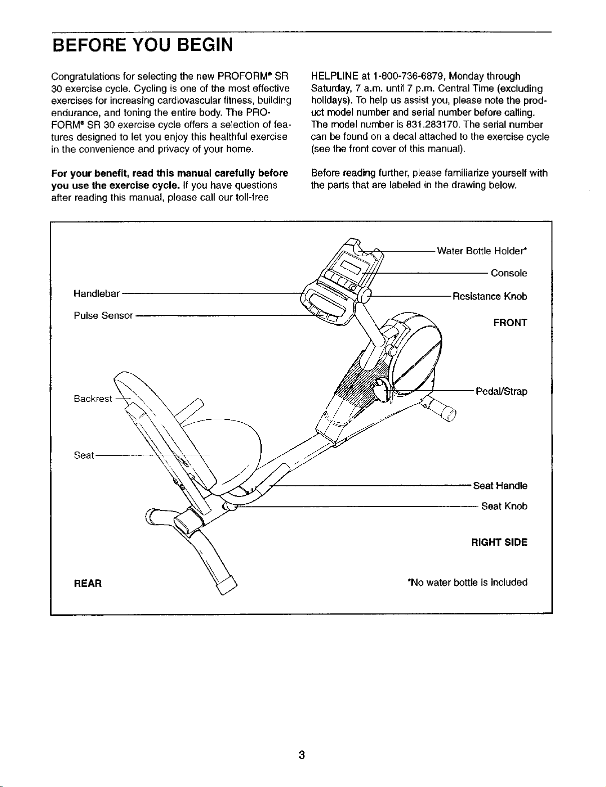
Handlebar
Pulse Sensor
HELPLINE at 1-800-736-6879, Monday through
Saturday, 7 a.m. until 7 p.m. Central Time (excluding
holidays). To help us assist you, please note the prod-
uct model number and serial number before calling.
The model number is831.283170. The serial number
can be found on a decal attached to the exercise cycle
(see the front cover ofthis manual).
Before reading further, please familiarize yourself with
the parts that are labeled in the drawing below.
Water Bottle Holder*
Console
Resistance Knob
FRONT
Seat
REAR
Pedal/Strap
Seat Handle
Seat Knob
RIGHT SIDE
*No water bottle is included
3

ASSEMBLY
Assembly requires two persons. Place all parts of the exercise cycle in a cleared area and remove the pack-
ing materials. Do not dispose of the packing materials until assembly is compTeted.
In addition to the included allen wrenches, assembly requires a phillips screwdriver _, an
adjustable wrench _:_::_, and a rubber mallet C _-_
As you assemble the exercise cycle, use the drawings below to identify the small parts used in assembly. The
number in parenthesis below each drawing refers to the key number of the part, from the PART LIST on page
14. The second number refers to the quantity used in assembly. Note: Some small parts may have been pre-
assembled for shipping. If a part is not in the parts bag, check to see if it has been pre-assembled.
L_J
M4x 16mm
Screw (40)-5
Screw (30)-1
MIO x 52mm Button Bolt (42)-2
M6 x 16mm
Screw (37)-5
M6 x 53mm
M6 Flat
Washer (38)-1
MIO x 80mm Button Bolt (49)-2
Washer (43)-8
M10 x 66mm Button Bolt(47)-4
MIO x 75mm Carriage Bolt (48)-2
M10 Split
MIO Nylon
Locknut (44)-6
D
4
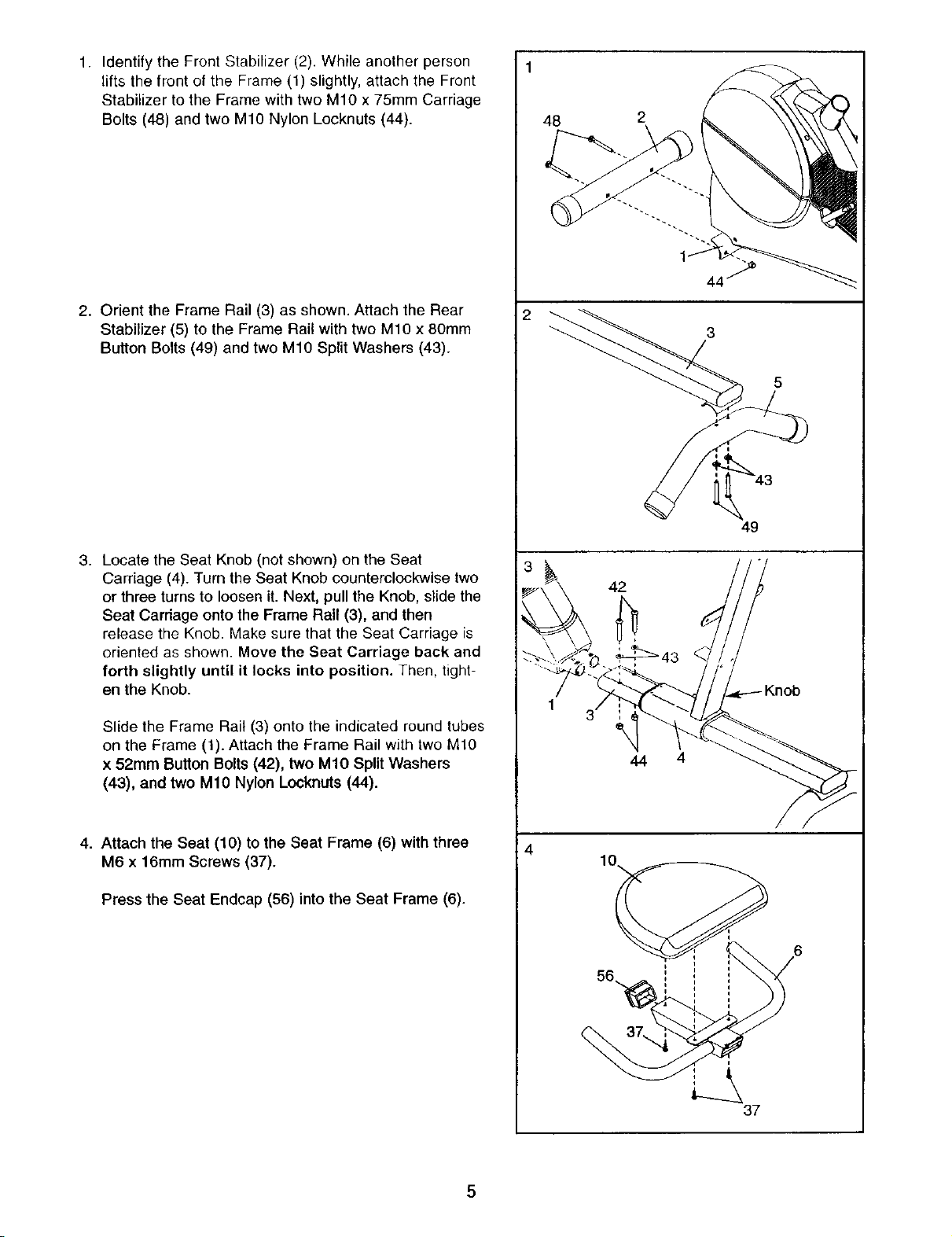
1. Identify the Front Stabilizer (2). While another person
lifts the front of the Frame (1) slightly, attach the Front
Stabilizer to the Frame with two M10 x 75mm Carriage
Bolts (48) and two M10 Nylon Locknuts (44).
2. Orient the Frame Rail (3) as shown. Attach the Rear
Stabilizer (5) to the Frame Rail with two M10 x 80mm
Button Bolts (49) and two M10 Split Washers (43).
2
5
3. Locate the Seat Knob (not shown) on the Seat
Carriage (4). Turn the Seat Knob counterclockwise two
or three turns to loosen it. Next, pu!l the Knob, slide the
Seat Carriage onto the Frame Rail (3), and then
release the Knob. Make sure that the Seat Carriage is
oriented as shown. Move the Seat Carriage back and
forth slightly until it locks into position. Then, tight-
en the Knob.
Slide the Frame Rail (3) onto the indicated round tubes
on the Frame (1). Attach the Frame Rail with two M10
x 52mm Button Bolts (42), two M10 Split Washers
(43), and two M10 Nylon Locknuts (44).
4. Attach the Seat (10) to the Seat Frame (6) with three
M6 x 16mm Screws (37).
Press the Seat Endcap (56) into the Seat Frame (6).
49
42
44 4
4
37
 Loading...