

Proform 831280170 Owner’s Manual
920 S
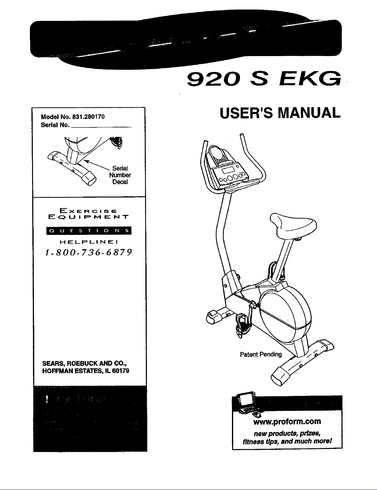
Model No. 831.280170
Serial No.
//I
EQUIPMENT
HELPLINE!
1-800-736-6879
USER'S MANUAL
Sedal
l_r
SEARS, ROEBUCK AND CO.,
HOFFMAN ESTATES, IL 60179
Patent Pending
www.proform.com
new products, prizes,
fitness tips, and much morel

TABLE OF CONTENTS
IMPORTANT PRECAUTIONS ............................................................. 2
BEFORE YOU BEGIN ................................................................... 3
ASSEMBLY ........................................................................... 4
HOW TO OPERATE THE EXERCISE CYCLE ................................................. 8
MAINTENANCE AND TROUBLE-SHOOTING ................................................. 11
CONDITIONING GUIDELINES ............................................................ 12
PART LIST ........................................................................... 14
EXPLODED DRAWING ................................................................. 15
HOW TO ORDER REPLACEMENT PARTS ........................................... Back Cover
FULL 90 DAY WARRANTY .................................................... Back Cover
2
BEFORE YOU BEGIN
Congratulations for selectingthe new PROFORIVP 920
S EKG exercise cycle. Cycling is one ofthe most
effective exemises for increasing cardiovascular fit-
ness, building endurance, and toning the entire body.
The PROFORM" 920 S EKG offers an impressive
array of features to let you enjoy this healthful exer-
cise in the convenience and pdvacy of your home.
For your benefit, read this manual carefully before
you use the exercise cycle. If you have questions
after reading the manual, please call our toll-free
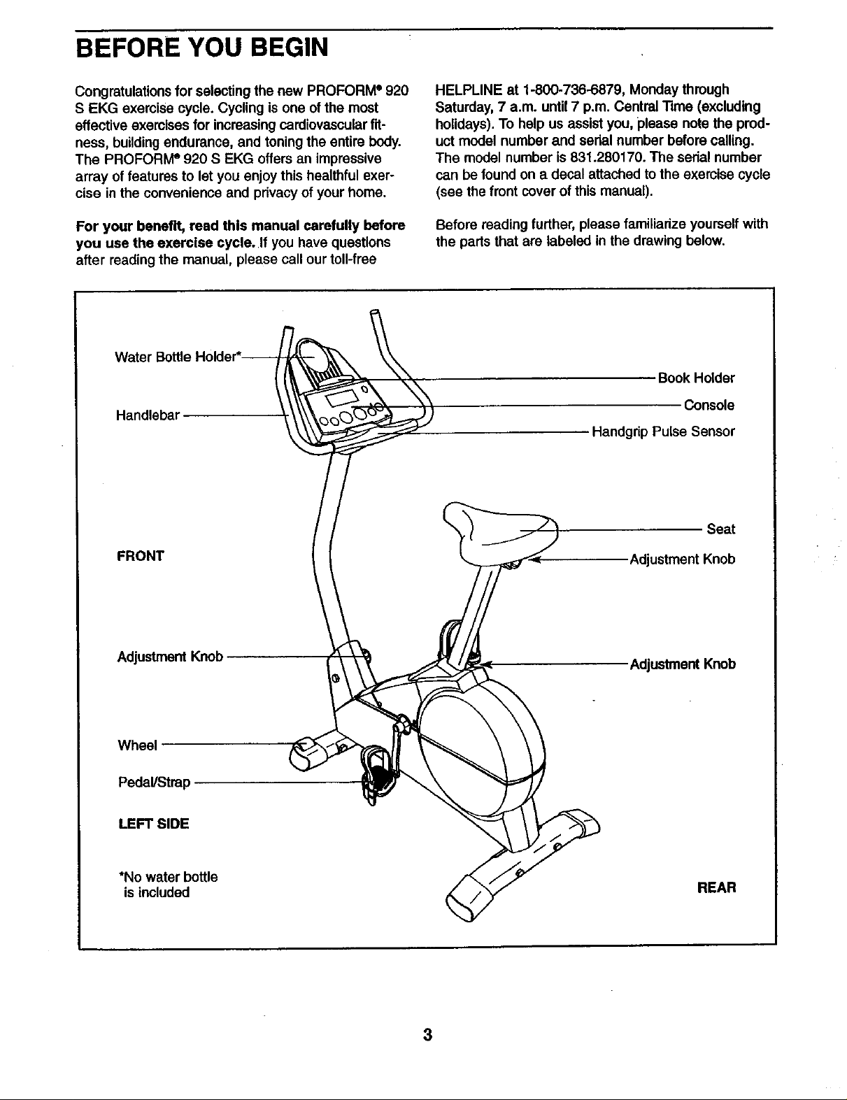
Handlebar
HELPLINE at 1-800-736-6879, Monday through
Saturday, 7 a.m. until 7 p.m. Central Time (excluding
holidays). To help us assist you, please note the prod-
uct model number and serial number before calling.
The model number is 831.280170. The sedal number
can be found on a decal attached to the exercise cycle
(see the front cover of this manual).
Before reading further, please familiarize yourselfwith
the parts that are labeled in the drawing below.
Book Holder
Console
Handgdp Pulse Sensor
FRONT
Adjustment Knob
Wheel
Pedal/Strap
LEFT SIDE
*No water bottle
is included
Seat
Adjustment Knob
AdjustmentKnob
REAR
3
ASSEMBLY
Assembly requires two persons. Place all parts of the exercise cycle in a cleared area and removethe packing
materials. Do not dispose ofthe packing materials until assembly is completed.
Assembly requires the included tools and your own adjustable wrench _ and
driver _.
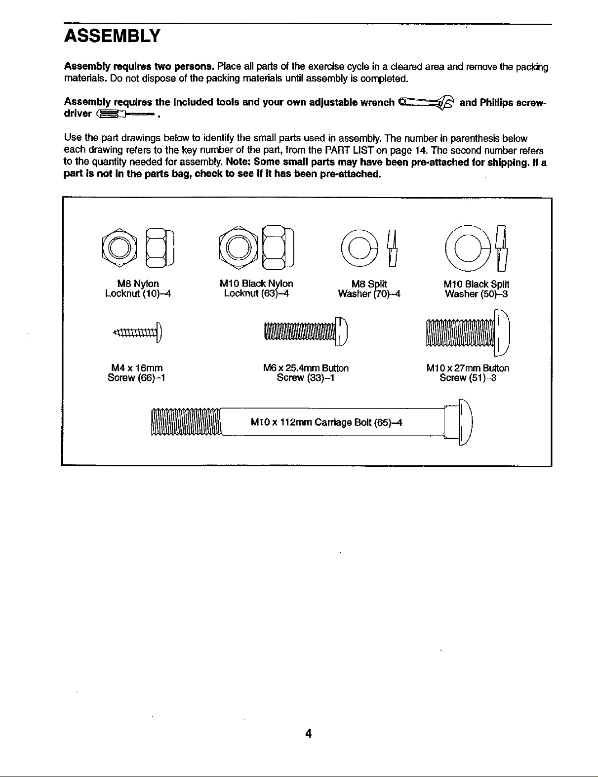
Use the part drawings below to identifythe small parts used inassembly. The number in parenthesis below
each drawing refers to the key number of the part, from the PART LIST on page 14. The second number refers
to the quantity needed for assembly. Note: Some small parts may have been pre-attached for shipping. If a
part is not in the parts bag, check to see if it has been pre-attached.
M8 Nylon
Locknut (10)-4
M4 x 16mm
Screw (66)-1
MIO Black Nylon
Locknut (63)-4
M6 x 25.4mm Button
Screw (33)-1
M8 Split
Washer (70)-4
M10 Black Split
Washer (50)-3
M10 x 27mm Button
Screw (51)-3
Phillips
screw-
MIO x 112mm Carriage Bolt (65)-4
4
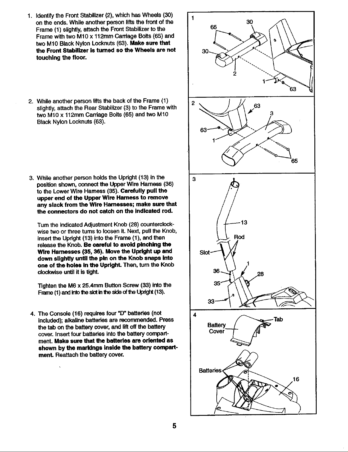
1. Identify the Front Stabilizer (2), which has Wheels (30)
on the ends. While another person liftsthe front of the
Frame (1) slightly, attach the Front Stabilizer to the
Frame with two M10 x 112mm Carriage Bolts (65) and
two M10 Black Nylon Locknuts (63). Make sure that
the Front Stabitizer Is turned so the Wheels are not
touching the floor.
65
30
2. While another person liftsthe back of the Frame (1)
slightly,attach the Rear Stabilizer (3) to the Frame with
two MtO x 112mm Carriage Bolts(65) and two M10
Black Nylon Locknuts (63).
3. While another person holds the Upright (13) in the
position shown, connect the Upper Wire Hamess (36)
to the Lower Wire Harness (35). Carefully pull the
upper end of the Upper Wire Hamess to remove
any slack from the Wire Harnesses; make sure that
the connectors do not catch on the indicated rod.
Tum the indicated Adjustment Knob (28) counterclock-
wise two or three tums to loosen it. Next, pullthe Knob,
insert the Upright (13) into the Frame (1), and then
release the Knob. Be careful to avoid pinching the
Wire Harnesses (35, 36). Move the Upright up and
down slightly until the pin on the Knob snaps Into
one of the holes In the Upright. Then, turn the Knob
clockwise until it is tight.
2
65
Tighten the M6 x 25.4mm Button Screw (33) Into the
Frame (1)and intothe slotinthesideofthe Upright(13).
4. The Console (16) requires four =D" batterlec (not
included); alkaline batteries are recommended. Press
the tab on the battery cover, and lift off the battery
cover. Insert four batteries intothe battery compart-
ment. Make sure that the batteries are oriented as
shown by the marldngs Inside the battery compart-
ment. Reattach the battery cover.
4
Battedes_
5
 Loading...