

Proform 831248650 Owner’s Manual
Model No. 831.24865.0
Serial No.
TREADMI LL EXERCISER
Write the serial number in the space
above for reference.
Serial Number _
Decal
. Assembly
. Operation
" Maintenance
o Part List and Drawing
User's Manual
Sears, Roebuck and Co., Hoffman Estates, IL 80179
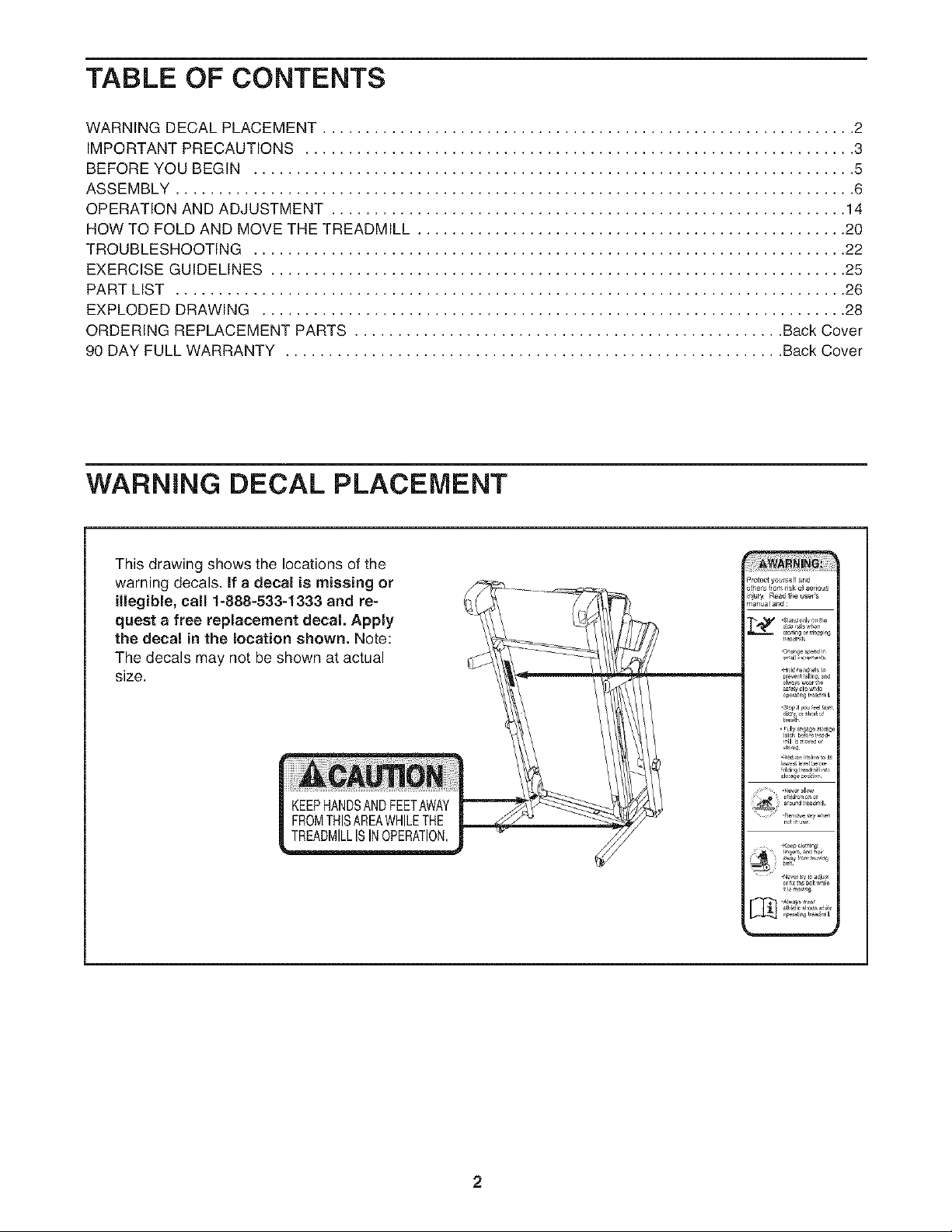
TABLE OF CONTENTS
WARNING DECAL PLACEMENT .............................................................. 2
IMPORTANT PRECAUTIONS ................................................................ 3
BEFORE YOU BEGIN ...................................................................... 5
ASSEMBLY ............................................................................... 6
OPERATION AND ADJUSTMENT ............................................................ 14
HOW TO FOLD AND MOVE THE TREADMILL .................................................. 20
TROUBLESHOOTING ..................................................................... 22
EXERCISE GUIDELINES ................................................................... 25
PART LIST .............................................................................. 26
EXPLODED DRAWING .................................................................... 28
ORDERING REPLACEMENT PARTS .................................................. Back Cover
90 DAY FULL WARRANTY .......................................................... Back Cover
WARNING DECAL PLACEMENT
This drawing shows the locations of the
warning decals. If a decal is missing or
illegible, call 1-888-533-1333 and re-
quest a free replacement decal. Apply
the decal in the location shown. Note:
The decals may not be shown at actual
size.
KEEPHANDSANDFEETAWAY
FROMTHISAREAWHILETHE
TREADMILLISINOPERATION,
2
iMPORTANT PRECAUTIONS
3
4
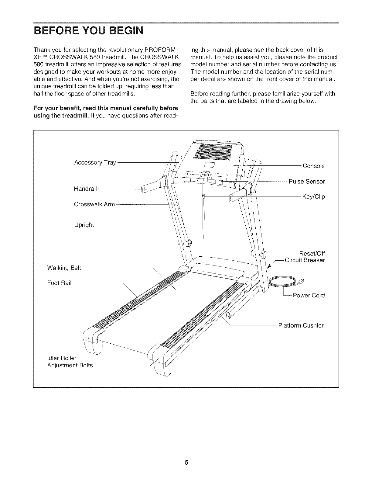
BEFORE YOU BEGIN
Thank you for selecting the revolutionary PROFORM
XP TM CROSSWALK 580 treadmill. The CROSSWALK
580 treadmill offers an impressive selection of features
designed to make your workouts at home more enjoy-
able and effective. And when you're not exercising, the
unique treadmill can be folded up, requiring less than
half the floor space of other treadmills.
For your benefit, read this manual carefully before
using the treadmill If you have questions after read-
Accessory Tray
Handrail
Crosswalk Arm
Upright
ing this manual, please see the back cover of this
manual. To help us assist you, please note the product
model number and serial number before contacting us.
The model number and the location of the serial num-
ber decal are shown on the front cover of this manual.
Before reading further, please familiarize yourself with
the parts that are labeled in the drawing below.
Console
Pulse Sensor
Key/Clip
Walking Belt
Foot Rail
Idler Roller
Adjustment Bolts
Reset/Off
_Circuit Breaker
\
Power Cord
Platform Cushion
5
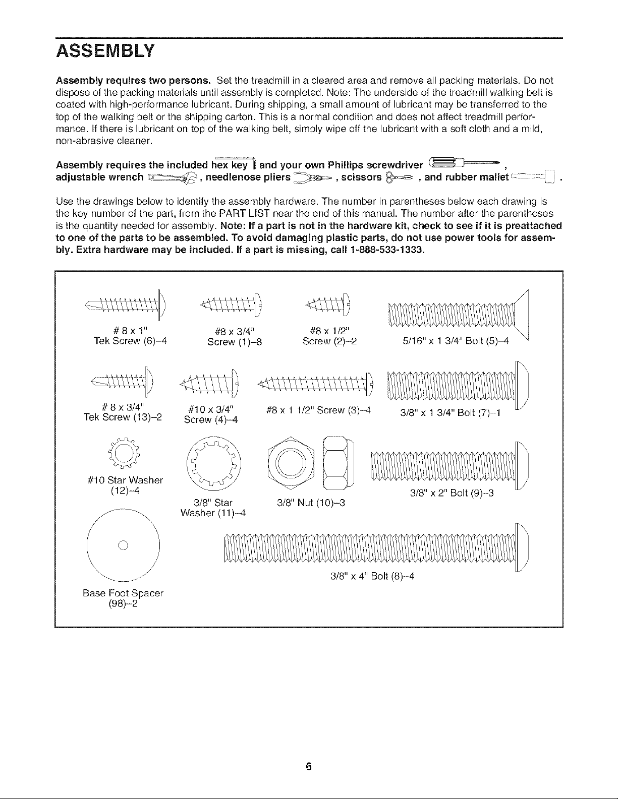
ASSEMBLY
Assembly requires two persons. Set the treadmill in a cleared area and remove all packing materials. Do not
dispose of the packing materials until assembly is completed. Note: The underside of the treadmill walking belt is
coated with high-performance lubricant. During shipping, a small amount of lubricant may be transferred to the
top of the walking belt or the shipping carton. This is a normal condition and does not affect treadmill perfor-
mance. If there is lubricant on top of the walking belt, simply wipe off the lubricant with a soft cloth and a mild,
non-abrasive cleaner.
Assembly requires the included h_ and your own Phillips screwdriver _ ,
adjustable wrench _, needlenose pliers _,=_, scissors _ , and rubber mallet.
Use the drawings below to identify the assembly hardware. The number in parentheses below each drawing is
the key number of the part, from the PART LIST near the end of this manual. The number after the parentheses
is the quantity needed for assembly. Note: If a part is not in the hardware kit, check to see if it is preattached
to one of the parts to be assembled. To avoid damaging plastic parts, do not use power tools for assem-
bly. Extra hardware may be included, if a part is missing, call 1-888-533-1333.
# 8 x 1" #8 x 3/4" #8 x 1/2"
Tek Screw (6)-4 Screw (1)-8 Screw (2)-2
5/16" x 1 3/4" Bolt (5)-4
# 8 x 3/4" #10 x 3/4"
Tek Screw (13)-2 Screw (4)-4
#10 Star Washer
(12)-4
3/8" Star
Washer (11)-4
x
\
Base Foot Spacer
(98)-2
#8 x 1 1/2" Screw (3)-4
3/8" Nut (10)-3
3/8" x 4" Bolt (8)-4
3/8" x 1 3/4" Bolt (7)-1
3/8" x 2" Bolt (9)-3
6
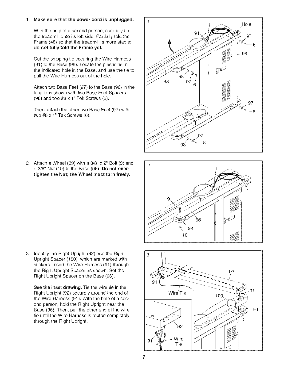
1. Make sure that the power cord is unplugged.
With the help of a second person, carefully tip
the treadmill onto its left side. Partially fold the
Frame (48) so that the treadmill is more stable;
do not fully fold the Frame yet.
Cut the shipping tie securing the Wire Harness
(91) to the Base (96). Locate the plastic tie in
the indicated hole in the Base, and use the tie to
pull the Wire Harness out of the hole.
Attach two Base Feet (97) to the Base (96) in the
locations shown with two Base Foot Spacers
(98) and two #8 x 1" Tek Screws (6).
Then, attach the other two Base Feet (97) with
two #8 x 1" Tek Screws (6).
Hole
/
97
98
2.
Attach a Wheel (99) with a 3/8" x 2" Bolt (9) and
a 3/8" Nut (10) to the Base (96). Do not over-
tighten the Nut; the Wheel must turn freely.
3.
Identify the Right Upright (92) and the Right
Upright Spacer (100), which are marked with
stickers. Insert the Wire Harness (91) through
the Right Upright Spacer as shown. Set the
Right Upright Spacer on the Base (96).
See the inset drawing. Tie the wire tie in the
Right Upright (92) securely around the end of
the Wire Harness (91). With the help of a sec-
ond person, hold the Right Upright near the
Base (96). Then, pull the other end of the wire
tie until the Wire Harness is routed completely
through the Right Upright.
2
¢ 99
\
10
92
Wire Tie
100
Tie
7
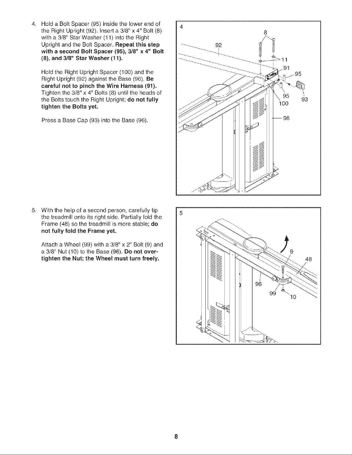
4,
Hold a Bolt Spacer (95) inside the lower end of
the Right Upright (92), Insert a 3/8" x 4" Bolt (8)
with a 3/8" Star Washer (11) into the Right
Upright and the Bolt Spacer, Repeat this step
with a second Bolt Spacer (95), 3/8" x 4" Bolt
(8), and 3/8" Star Washer (11).
Hold the Right Upright Spacer (100) and the
Right Upright (92) against the Base (96). Be
careful not to pinch the Wire Harness (91).
Tighten the 3/8" x 4" Bolts (8) until the heads of
the Bolts touch the Right Upright; do not fully
tighten the Bolts yet.
Press a Base Cap (93) into the Base (96).
4
8
92
100
93
5,
With the help of a second person, carefully tip
the treadmill onto its right side. Partially fold the
Frame (48) so the treadmill is more stable; do
not fully fold the Frame yet.
Attach a Wheel (99) with a 3/8" x 2" Bolt (9) and
a 3/8" Nut (10) to the Base (96). Do not over-
tighten the Nut; the Wheel must turn freely. 48
10
8
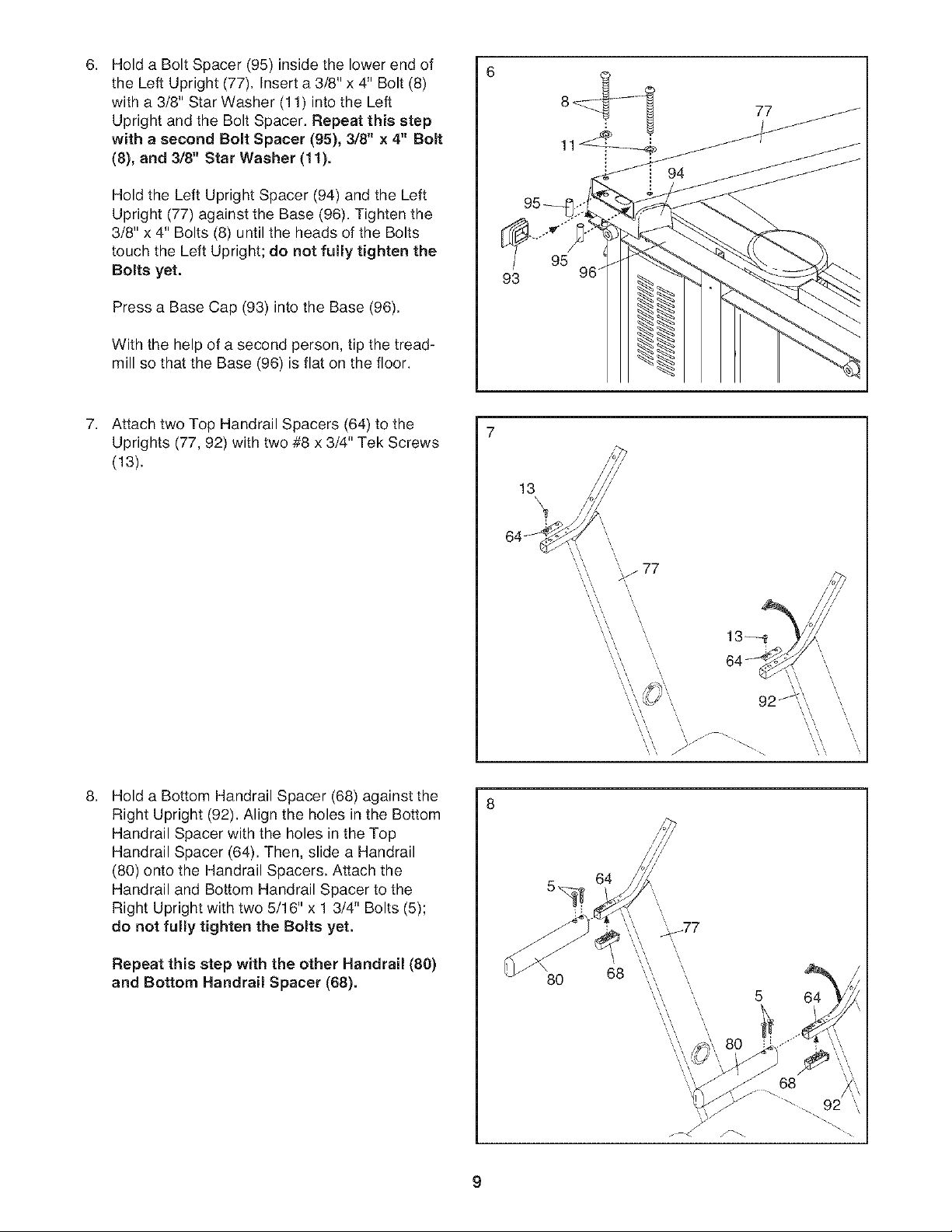
6.
Hold a Bolt Spacer (95) inside the lower end of
the Left Upright (77). Insert a 3/8" x 4" Bolt (8)
with a 3/8" Star Washer (11) into the Left
Upright and the Bolt Spacer. Repeat this step
with a second Bolt Spacer (95), 3/8" x 4" Bolt
(8), and 3/8" Star Washer (11).
Hold the Left Upright Spacer (94) and the Left
Upright (77) against the Base (96). Tighten the
3/8" x 4" Bolts (8) until the heads of the Bolts
touch the Left Upright; do not fully tighten the
Bolts yet.
Press a Base Cap (93) into the Base (96).
With the help of a second person, tip the tread-
mill so that the Base (96) is flat on the floor.
7.
Attach two Top Handrail Spacers (64) to the
Uprights (77, 92) with two #8 x 3/4" Tek Screws
(13).
6
95
96
13
\
.
Hold a Bottom Handrail Spacer (68) against the
Right Upright (92). Align the holes in the Bottom
Handrail Spacer with the holes in the Top
Handrail Spacer (64). Then, slide a Handrail
(80) onto the Handrail Spacers. Attach the
Handrail and Bottom Handrail Spacer to the
Right Upright with two 5/16" x 1 3/4" Bolts (5);
do not fully tighten the Bolts yet.
Repeat this step with the other Handrail (80)
and Bottom Handrail Spacer (88).
64_
'_ 77
...,.
\
\ /J j _.
8
64
80
68
\
\
5 64
68
f_
9

Set the console assembly face down on a soft
9. 9
surface to avoid scratching the console assem-
bly. Remove the two #8 x 3/4" Screws (1). Lift
off the Pulse Bar (110). Save the Pulse Bar
and the two Screws for assembly steps 10
and 12.
110
Console
Assembly
10. Set the Pulse Bar (110) on the Left and Right
Uprights (77, 92). Attach the Pulse Bar with four
#10 x 3/4" Screws (4) and four #10 Star
Washers (12). Start all four Screws before
firmly tightening any of them. Be careful not
to pinch the Wire Harness (91).
Firmly tighten the four 5/16" x 1 3/4" Bolts
(5).
11. While a second person holds the console as-
sembly near the Pulse Bar (110), connect the
Console Ground Wire (109) on the Pulse Bar to
the ground wire from the console assembly.
10
110
11 Console Console
Assembly Wire_
Connect the console wire to the Wire Harness
(91). See the inset drawing. The connectors
should slide together easily and snap into
place. If they do not, turn one connector and
then try again. IF THE CONNECTORS ARE
NOT CONNECTED PROPERLY, THE CON-
SOLE MAY BE DAMAGED WHEN THE
POWER IS TURNED ON. Lay the wires inside
the bottom of the Pulse Bar (110).
Ground
Wire
10
 Loading...