

ProForm 831.24843.0 User Manual
397
Model No. 831.24843.0
Serial No,
Write 1he serial number in the space
above for reterence,
Decal
• Assembly
• Operation
• Maintenance
. Part List and Drawing
Sears, Roebuok and Co.
Hoffman Estates, ]L 60179
TREADMILL EXERCISER
User's Manual
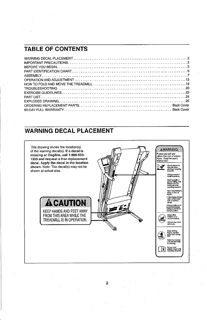
TABLE OF CONTENTS
WARNING DECAL PLACEMENT ............................................................... 2
IMPORTANT PRECAUTIONS .................................................................. 3
BEFORE YOU BEGIN ........................................................................ 5
PART IDENTIFICATION CHART, ............................................................... 6
ASSEMBLY ................................................................................ 7
OPERATION AND ADJUSTMENT ................................. _ ........................... t3
HOW TO FOLD AND MOVE THE TREADMILL ................................................... I9
TROUBLESHOOTING ........ .............................................................. 20
EXERCISE GUIDELINES .................................................................... 23
PART LIST ................................................................................ 24
EXPLODED DRAWING ...................................................................... 25
ORDERING REPLACEMENT PARTS_ .................................................. Back Cover
90-DAY FULL WARRANTY ........................................................... Back Cover
WARNING DECAL PLACEMENT
This drawing shows the location[s)
of the warning decal(s), if a decal is
missing or illegible, call 1-888,-533-
1333 and request a free replacement
decal, Apply the decal in the location
shown. Note: The decal(s) may not be
shown at actual size.
KEEPHANDSANDFEE-I'AWAY
FROMTHISAREAWHILETHE
TREADMILLISINOPERATION.
2
IMPORTANT PRECAUTIONS
BEFORE YOU BEGIN
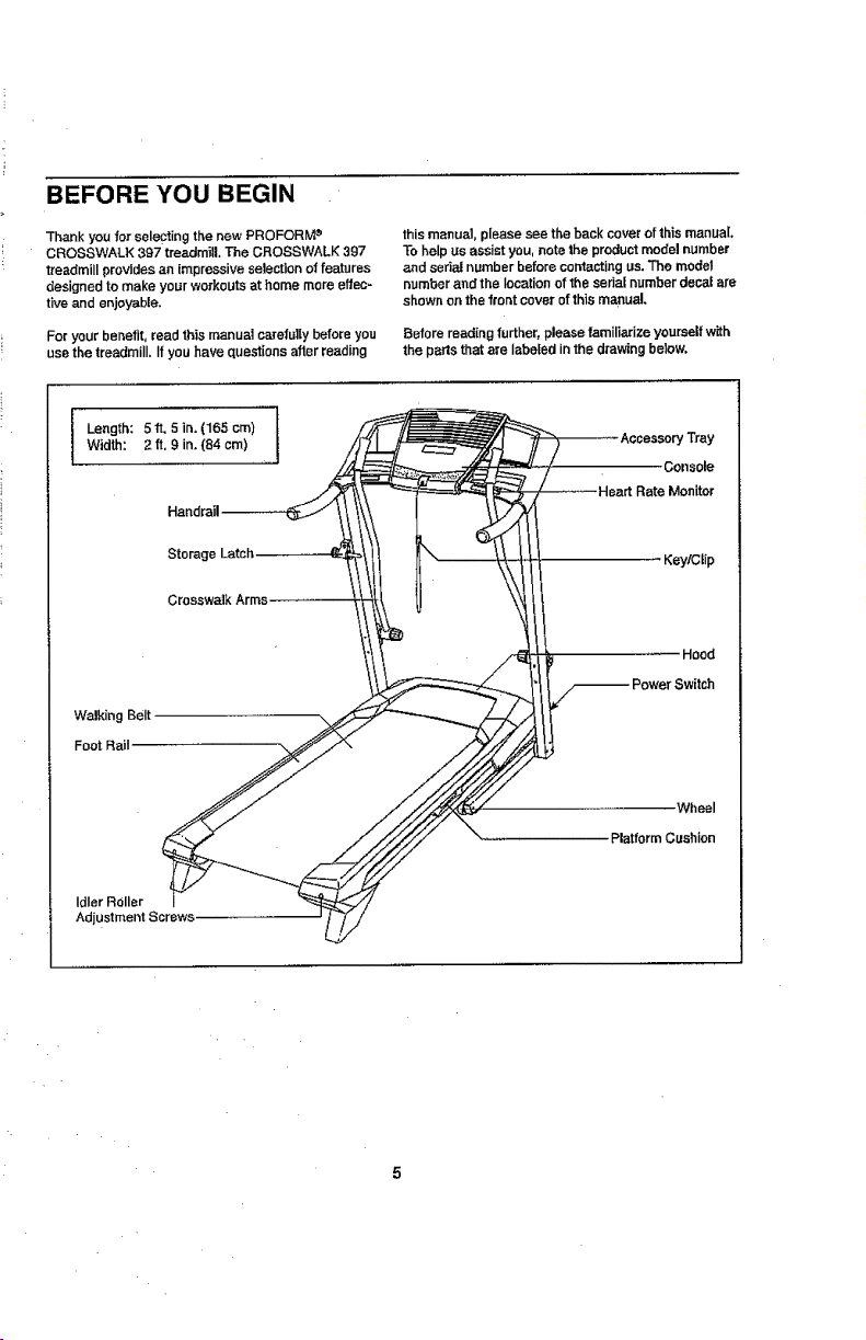
Thank you for seleCting the new PROFORM e
CROSSWALK 397 treadmill, The CROSSWALK 397
treadmill provides an impressive selection of features
designed to make your workoutS at home more effec-
tive and enjoyable,
For your benefit, readthis manual carefullybefore you
use the treadmill. If you have questions after reading
Width: 2 ft. 9 in. (84 em)
I Length: 5ft, 5in,(165cm) i
Storag_
Crosswalk
Walking Belt
Foot Rail
this manuaJ,p[easesee the back cover ofthis manual.
To helpus assistyou, note the productmodel number
and sedal number before contactingus.The model
numberand the location of the serial number decal are
shownon the front coverof this manual.
Before reading further, please familiarize yourselfwith
the partsthat are labeled in the drawingbelow,
,Console
Monitor
KeylCtip
Hood
Wheel
Platform Cushion
Idler Roller
Adjustment Screws.
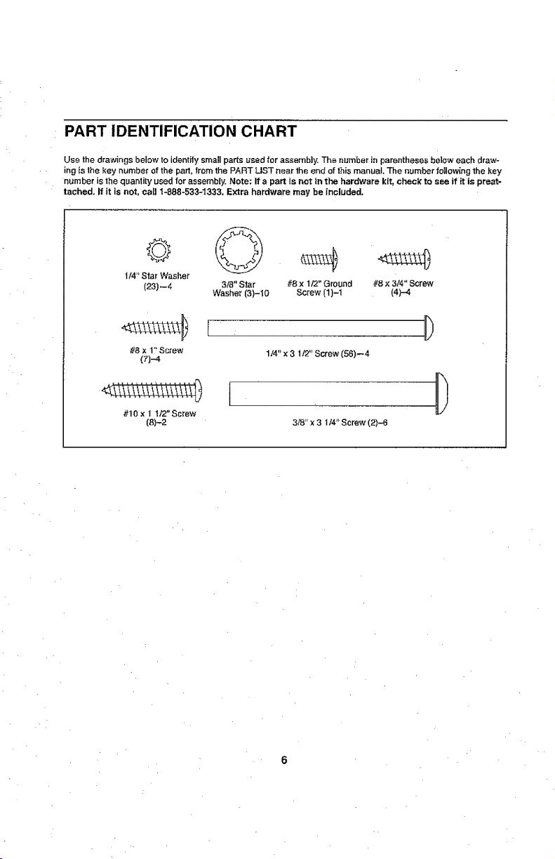
PART IDENTIFICATION CHART
Use the drawings below to identify small parts used for assembly. The number in parentheses below each draw-
ing is the key number of the part, tram the PART LIST near the end of this manual, The number following 1he key
number is the quantity used for assembly. Note: If a part is not in the hardware kit, check to see if it is preat-
tached, If it is not, carl 1-888-533_1,333. Extra hardware may be included,
I/4" Star Washer
(23)--4 3/8" Star #8 x 1/2" Ground #8 x 3/4" Screw
#8 x 1" Screw 1/4" x 3 1/2" Screw (56)--4
(7)-4
Washer (3)-t0 Screw (1)-1 (4)-4
!iii iii!ii :\iiii
#10 x t 1t2"Ssrew
(8)-2
I
3,."8"x3 1/4" Screw (2)-6
D
ASSEMBLY
• Assembly requires two persons.
• Place all parts in a cleared area and remove the
packing materials. Do not dispose of the packing
materials until you finish assembly.
• The underside of the walking belt is coated with
high-pedormance lubricant. After shipping, there
may be some lubricant on fop of the walking belt
or on the shipping carton. This is normal. If there
is lubricant on top of the walking belt, wipe it oN
with a soft cloth and a mild, non-abrasive cleaner.
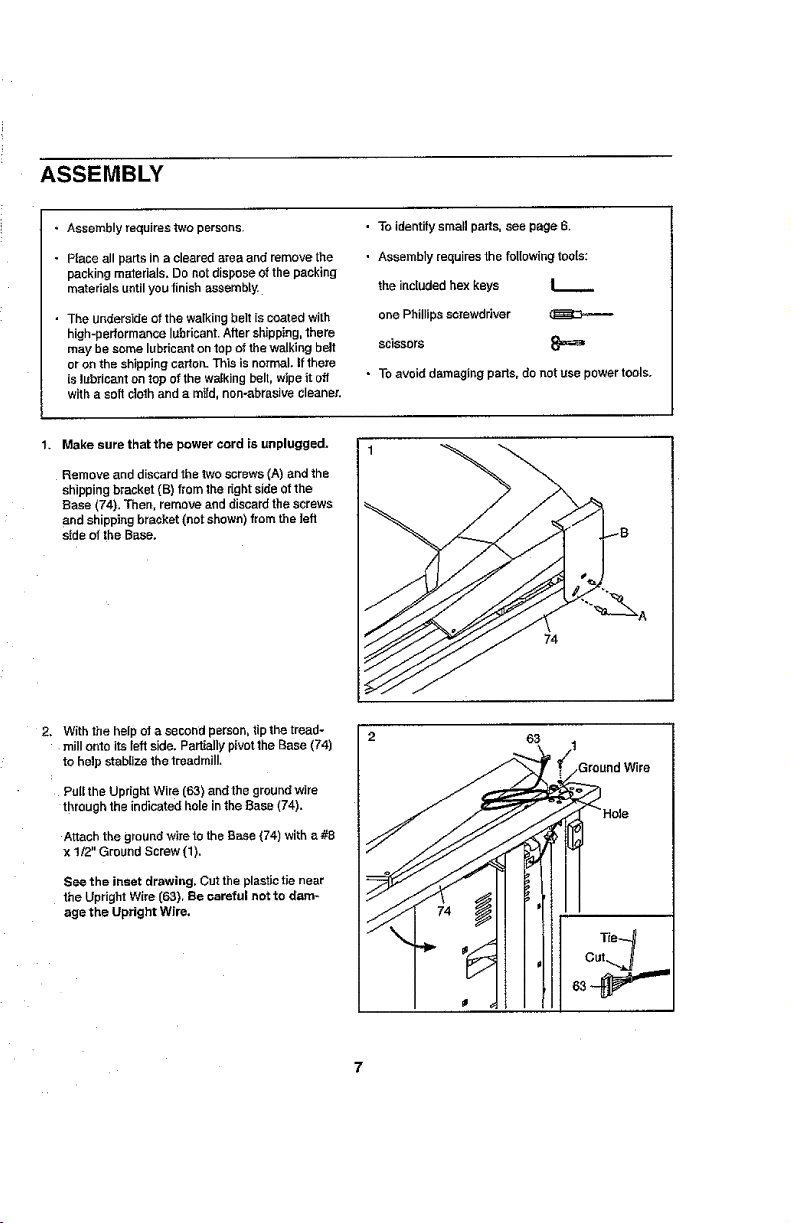
1. Make sure that the power cord is unplugged.
Remove and discardthetwo screws(A) and the
shipping bracket (B) from the r_ghtside ofthe
Base (74). 3"hen,remove and discard the screws
and shipping bracket (not shown)from the left
side of the Base.
2. With the help of a second person, tip the tread-
mill onto its left side. PaPally pivot the Base (74)
to help stabUze the treadmill.
Pull the Upright Wire (63) and the ground wire
through the indicated hole in the Base (74).
Attach the groundwire te the Base (74) witha#8
x 1/2" Ground Screw (1).
See the inset drawing, Cut the plastic tie near
the Upright Wire (63). Be careful not to dam-
age the Upright Wire,
• To identify small paris, see page 6.
• Assembly requires the following tools:
the included hex keys |
one Phillips screwdriver
scissors 8=_
• To avoid damaging parts, do net use power tools,
74
2 63
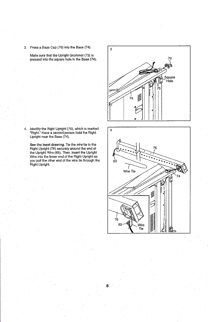
3.PressaBaseCap(70)intotheBase(74).
MakesurethattheUprightGrommet(73)is
pressedinlothesquareholeintheBase(74).
4.Identifythe Right UPright (76), which is marked
"Right. ° Have a second person hold the Right
Upright near lhe Base (74).
See the inset drawing. Tie the wire tie in the
Right Upright (76) securely around the end of
the Upright Wire (63). Then, insert the Upright
Wire into the lower end of the Right Upright as
you pull the other end of the wire tie through the
Right Upright,
7O
76
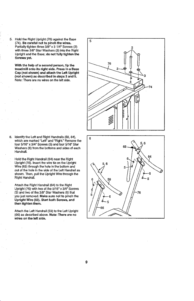
Hold the Right Upright (76) against the Base
(74). Be careful not to pinch the wires,
Partially tighten three 3/8" x 3 1/4" Screws (2)
with three 3t8" Star Washers (3) into the Right
Upright and the Base; do not fully tighten the
Screws yet.
With the help of a second person, tip the
treadmill onto its right side. Press in a Base
Cap (not shown) and attach the Left Upright
(not shown) as described in steps 3 and 5,
Note: There are no wires on the left side.
6, Identify the Left and Right Handrails (59, 64),
which are marked "Left" and URight." Remove the
four 5f16" x 3/4" Screws (5) and four 5/16" Star
Washers (6) from the bottoms and sides of each
Handrail,
Hold the Right Handrail (64) near the Right
Upright (76). Insert the wire tie on the Upright
Wire {63) through the hole in the bottom and
out of the hole in the side of the Left Handrail as
shown. Then, pull the Upright Wire through the
Right Handrail.
Attach the Right Handrail (64) to the Right
Upright (76) with fwo of the 5/16" x 3f4" Screws
(5) and two of the 3/8" Star Washers (6) that
you just removed. Make sure not to pinch the
Upright Wire (63), Start both Screws, and
then tighten them.
Attach the Left Handrail (59) to the Left Upright
(66) as described above. Note: There are no
wires on the left side,
59
 Loading...