

Proform 831248242 Owner’s Manual
Model No. 831.24824.2
Serial No.
TR A ILL
SE
Write the serial number in the space
above for future reference.
Serial
Number
Decal
• Assembly
• Operation
• Maintenance
• Part List and Drawing
User's
Manual
Sears, Roebuck and Co., Hoffman Estates, IL 60179

TABLE OF CONTENTS
WARNING DECAL PLACEMENT .............................................................. 2
IMPORTANT PRECAUTIONS ................................................................ 3
BEFORE YOU BEGIN ...................................................................... 5
ASSEMBLY ............................................................................... 6
OPERATION AND ADJUSTMENT ............................................................ 14
HOW TO FOLD AND MOVE THE TREADMILL .................................................. 20
TROUBLESHOOTING ..................................................................... 22
EXERCISE GUIDELINES ................................................................... 25
PART LIST .............................................................................. 26
EXPLODED DRAWING .................................................................... 28
ORDERING REPLACEMENT PARTS .................................................. Back Cover
90 DAY FULL WARRANTY .......................................................... Back Cover
WARNING DECAL PLACEMENT
This drawing shows the locations of the warning de-
cals, If a decal is missing or illegible, call 1-888-533-
1333 and request a free replacement decal. Apply
the decal in the location shown. Note: The decals
may not be shown at actual size.
Protect yourself and
others from risk of serious
injury. Read the user's
manual and :
side rails when
•Stand only on the
sa_n orso n
KEEPHANDSANDFEETAWAY
FROMTHISAREAWHILETHE
TREADMILLISINOPERATION.
•Hold handrails to
p[eveni fail,r,g, and
always wear the
safety clip wile
operating i[eadm_ll.
•Stop if you feel laJnb
dizzy, or shod of
b_eath.
• Fully e_'gage storage
latch before tread-
roll s moved or
stored
.Reduce _nelJne to its
lowest level befo[e
foldk*g [readmill into
sio_age position
: o............
arour_ treadmill,
"Remove key when
not in use,
.Keep clothing.
_wty_........ _g
[
•Never try to ad}ust
or fix the belt wNle
_tis moving
athletEc shoes while
_] "Always wear
operating treadmill.
2

iMPORTANT PRECAUTIONS
3
4
BEFORE YOU BEGIN
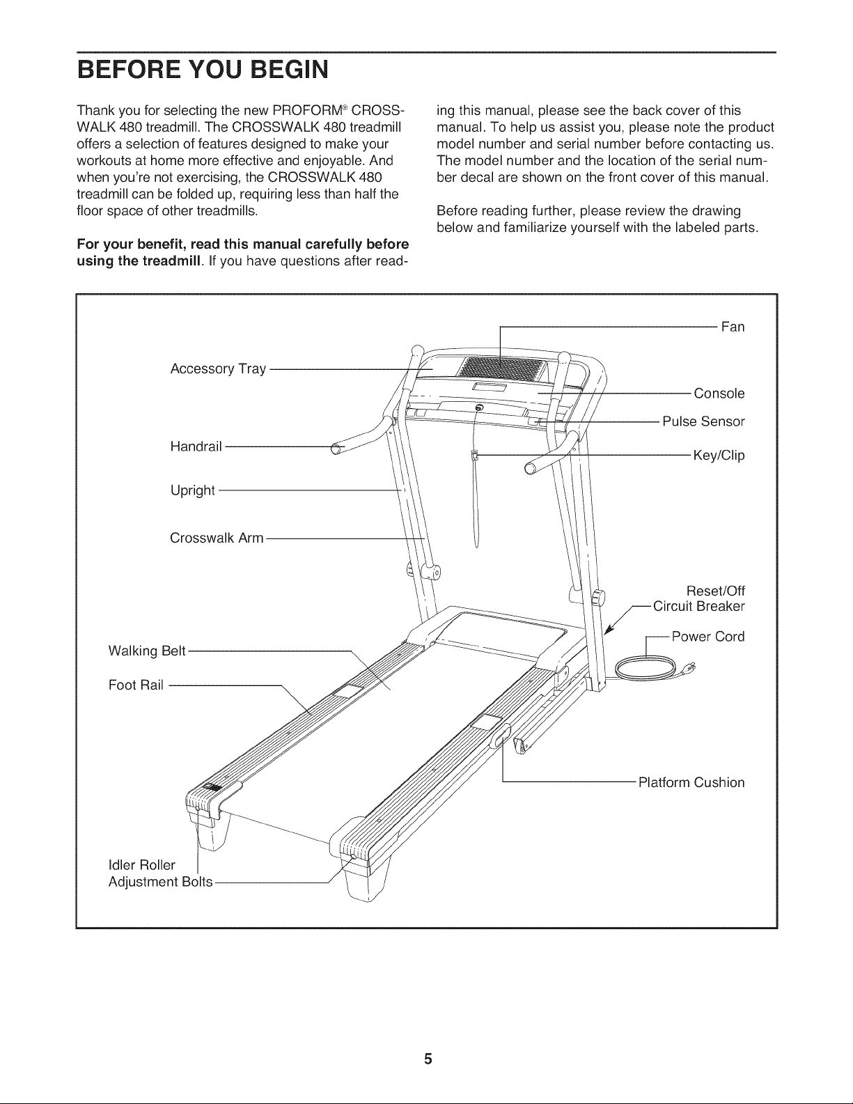
Thank you for selecting the new PROFORM ®CROSS-
WALK 480 treadmill. The CROSSWALK 480 treadmill
offers a selection of features designed to make your
workouts at home more effective and enjoyable. And
when you're not exercising, the CROSSWALK 480
treadmill can be folded up, requiring less than half the
floor space of other treadmills.
For your benefit, read this manual carefully before
using the treadmill. If you have questions after read-
Accessory Tray
Handrail
Upright
ing this manual, please see the back cover of this
manual. To help us assist you, please note the product
model number and serial number before contacting us.
The model number and the location of the serial num-
ber decal are shown on the front cover of this manual.
Before reading further, please review the drawing
below and familiarize yourself with the labeled parts.
Fan
Console
Pulse Sensor
Key/Clip
Crosswalk Arm
Walking Belt
Foot Rail
Idler Roller
Adjustment Bolts
Reset/Off
Breaker
Cord
\
Platform Cushion
5
ASSEMBLY
Assembly requires two persons. Set the treadmill in a cleared area and remove all packing materials. Do not
dispose of the packing materials until assembly is completed. Note: The underside of the treadmill walking
belt is coated with high-performance lubricant. During shipping, a small amount of lubricant may be transferred to
the top of the walking belt or the shipping carton. This is a normal condition and does not affect treadmill perfor-
mance. If there is lubricant on top of the walking belt, simply wipe off the lubricant with a soft cloth and a mild,
non-abrasive cleaner.
Assembly requires the included hex keys _ and your own Phillips screwdriver (__,
adjustable wrench _, and scissors _=_.
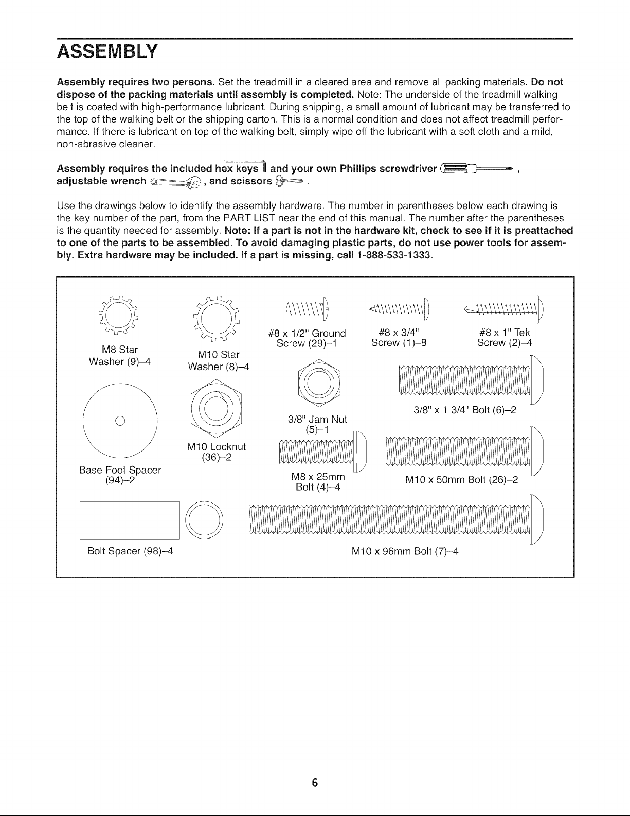
Use the drawings below to identify the assembly hardware. The number in parentheses below each drawing is
the key number of the part, from the PART LIST near the end of this manual. The number after the parentheses
is the quantity needed for assembly. Note: If a part is not in the hardware kit, check to see if it is preattached
to one of the parts to be assembled. To avoid damaging plastic parts, do not use power tools for assem-
bly. Extra hardware may be included. If a part is missing, call 1-888-533-1333.
O
#8 x 1/2" Ground #8 x 3/4" #8 x 1" Tek
M8 Star
Washer (9)-4
Base Foot Spacer
(94)-2
Bolt Spacer (98)-4 M10 x 96mm Bolt (7)-4
M10 Star
Washer (8)-4
M10 Locknut
(36)-2
Screw (29)-1 Screw (1)-8 Screw (2)-4
3/8" Jam Nut
(5)-1
M8 x 25mm
Bolt (4)-4
3/8" x 1 3/4" Bolt (6)-2
M10 x 50mm Bolt (26)-2
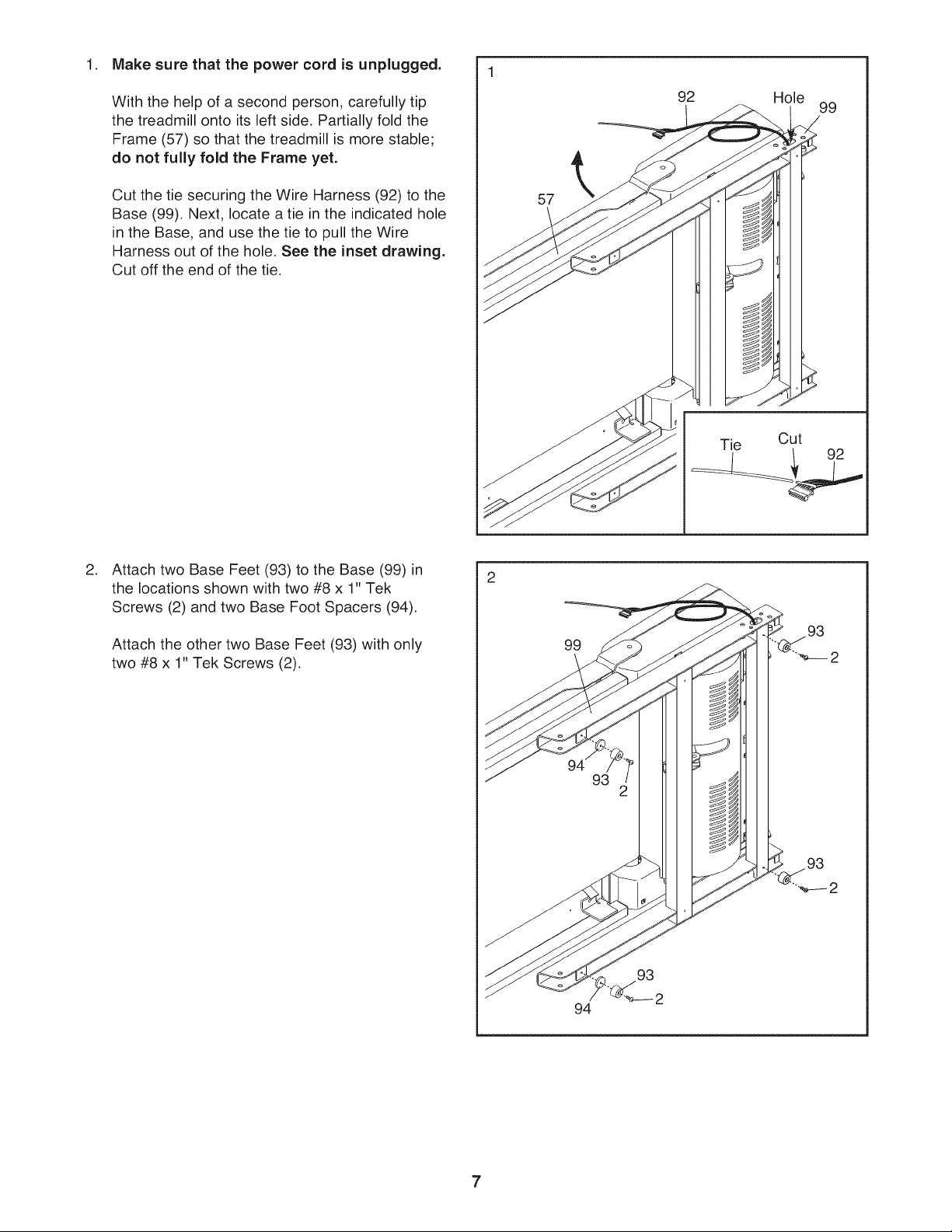
1. Make sure that the power cord is unplugged.
With the help of a second person, carefully tip
the treadmill onto its left side. Partially fold the
Frame (57) so that the treadmill is more stable;
do not fully fold the Frame yet.
Cut the tie securing the Wire Harness (92) to the
Base (99). Next, locate a tie in the indicated hole
in the Base, and use the tie to pull the Wire
Harness out of the hole. See the inset drawing.
Cut off the end of the tie.
57
92
Hole
Tie Cut
I 1 92
99
,
Attach two Base Feet (93) to the Base (99) in
the locations shown with two #8 x 1" Tek
Screws (2) and two Base Foot Spacers (94).
Attach the other two Base Feet (93) with only
two #8 x 1" Tek Screws (2).
99
2
93
94
.
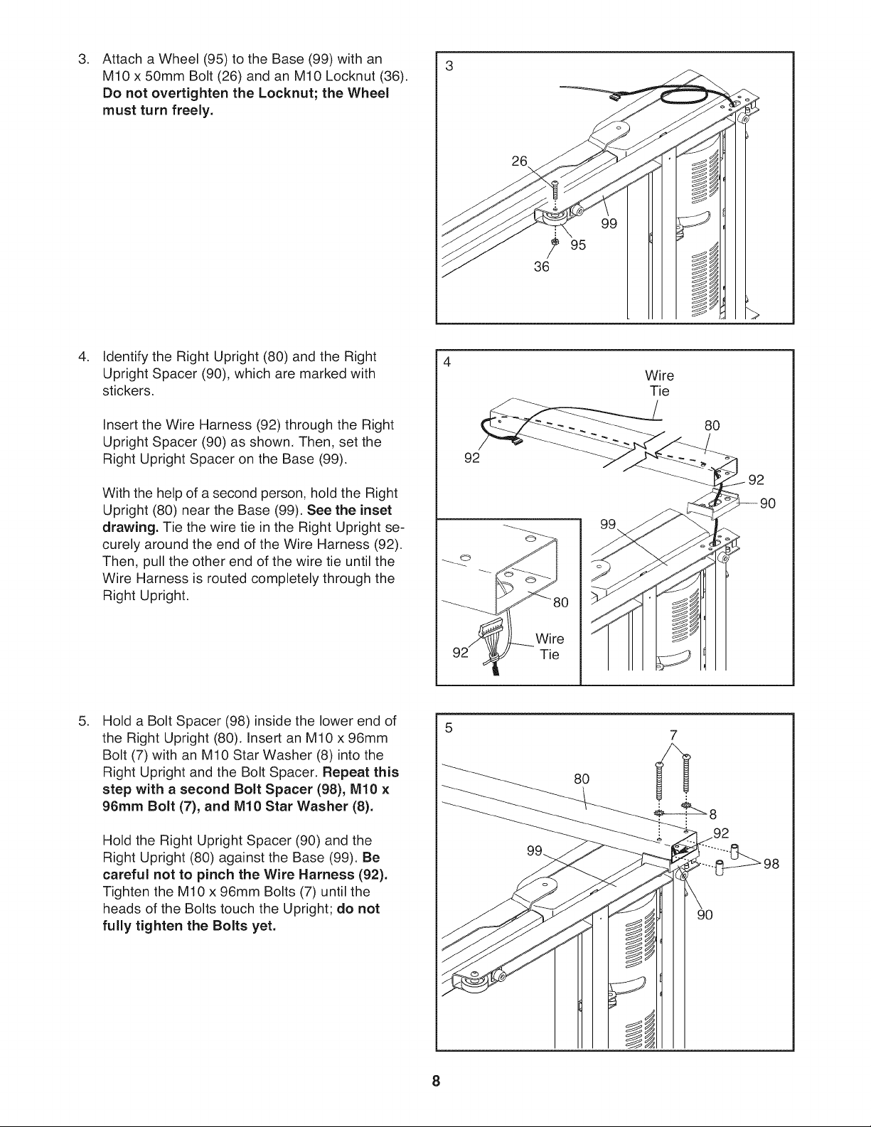
Attach a Wheel (95) to the Base (99) with an
M10 x 50mm Bolt (26) and an M10 Locknut (36).
Do not overtighten the Locknut; the Wheel
must turn freely.
.
Identify the Right Upright (80) and the Right
Upright Spacer (90), which are marked with
stickers.
J
,d
<
\
95
Wire
Tie
Insert the Wire Harness (92) through the Right
Upright Spacer (90) as shown, Then, set the
Right Upright Spacer on the Base (99).
With the help of a second person, hold the Right
Upright (80) near the Base (99), See the inset
drawing. Tie the wire tie in the Right Upright se-
curely around the end of the Wire Harness (92).
Then, pull the other end of the wire tie until the
Wire Harness is routed completely through the
Right Upright.
.
Hold a Bolt Spacer (98) inside the lower end of
the Right Upright (80), Insert an M10 x 96mm
Bolt (7) with an M10 Star Washer (8) into the
Right Upright and the Bolt Spacer, Repeat this
step with a second Bolt Spacer (98), M10 x
96ram Bolt (7), and M10 Star Washer (8).
Hold the Right Upright Spacer (90) and the
Right Upright (80) against the Base (99). Be
careful not to pinch the Wire Harness (92).
Tighten the M10 x 96mm Bolts (7) until the
heads of the Bolts touch the Upright; do not
fully tighten the Bolts yet.
92
Wire
Tie
80
92
o
80
92
90
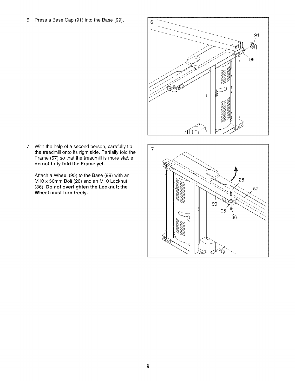
6. PressaBaseCap(91)intotheBase(99). 6
,
With the help of a second person, carefully tip
the treadmill onto its right side, Partially fold the
Frame (57) so that the treadmill is more stable;
do not fully fold the Frame yet.
91
99
Attach a Wheel (95) to the Base (99) with an
M10 x 50mm Bolt (26) and an M10 Locknut
(36). Do not overtighten the Locknut; the
Wheel must turn freely.
57
g
.
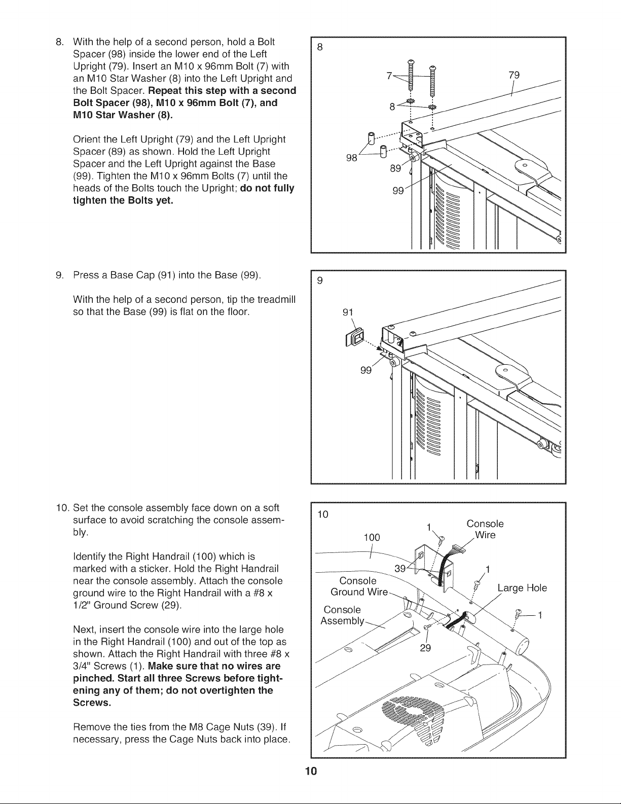
With the help of a second person, hold a Bolt
8
Spacer (98) inside the lower end of the Left
Upright (79). Insert an M10 x 96mm Bolt (7) with
an M10 Star Washer (8) into the Left Upright and
the Bolt Spacer. Repeat this step with a second
Bolt Spacer (98), M10 × 96mm Bolt (7), and
M10 Star Washer (8).
Orient the Left Upright (79) and the Left Upright
Spacer (89) as shown. Hold the Left Upright
Spacer and the Left Upright against the Base
(99). Tighten the M10 x 96mm Bolts (7) until the
heads of the Bolts touch the Upright; do not fully
tighten the Bolts yet.
.
Press a Base Cap (91) into the Base (99).
With the help of a second person, tip the treadmill
so that the Base (99) is flat on the floor. 91
79
98
10. Set the console assembly face down on a soft
surface to avoid scratching the console assem-
bly.
Identify the Right Handrail (100) which is
marked with a sticker. Hold the Right Handrail
near the console assembly. Attach the console
ground wire to the Right Handrail with a #8 x
1/2" Ground Screw (29).
Next, insert the console wire into the large hole
in the Right Handrail (100) and out of the top as
shown. Attach the Right Handrail with three #8 x
3/4" Screws (1). Make sure that no wires are
pinched. Start all three Screws before tight-
ening any of them; do not overtighten the
Screws.
Remove the ties from the M8 Cage Nuts (39). If
necessary, press the Cage Nuts back into place.
10
10
Console
Ground
Console
Assembl,
100
1 Console
Wire
• Large Hole
 Loading...