


Proform 831248031 Owner’s Manual
Model No. 831.24803.1
Serial No.
TR A ILL
SE
Write the serial number in the space
above for future reference.
Serial Number
Decal
• Assembly
• Operation
• Maintenance
• Part List and Drawing
User's
Manual
Sears, Roebuck and Co.,
Hoffman Estates, IL 60179
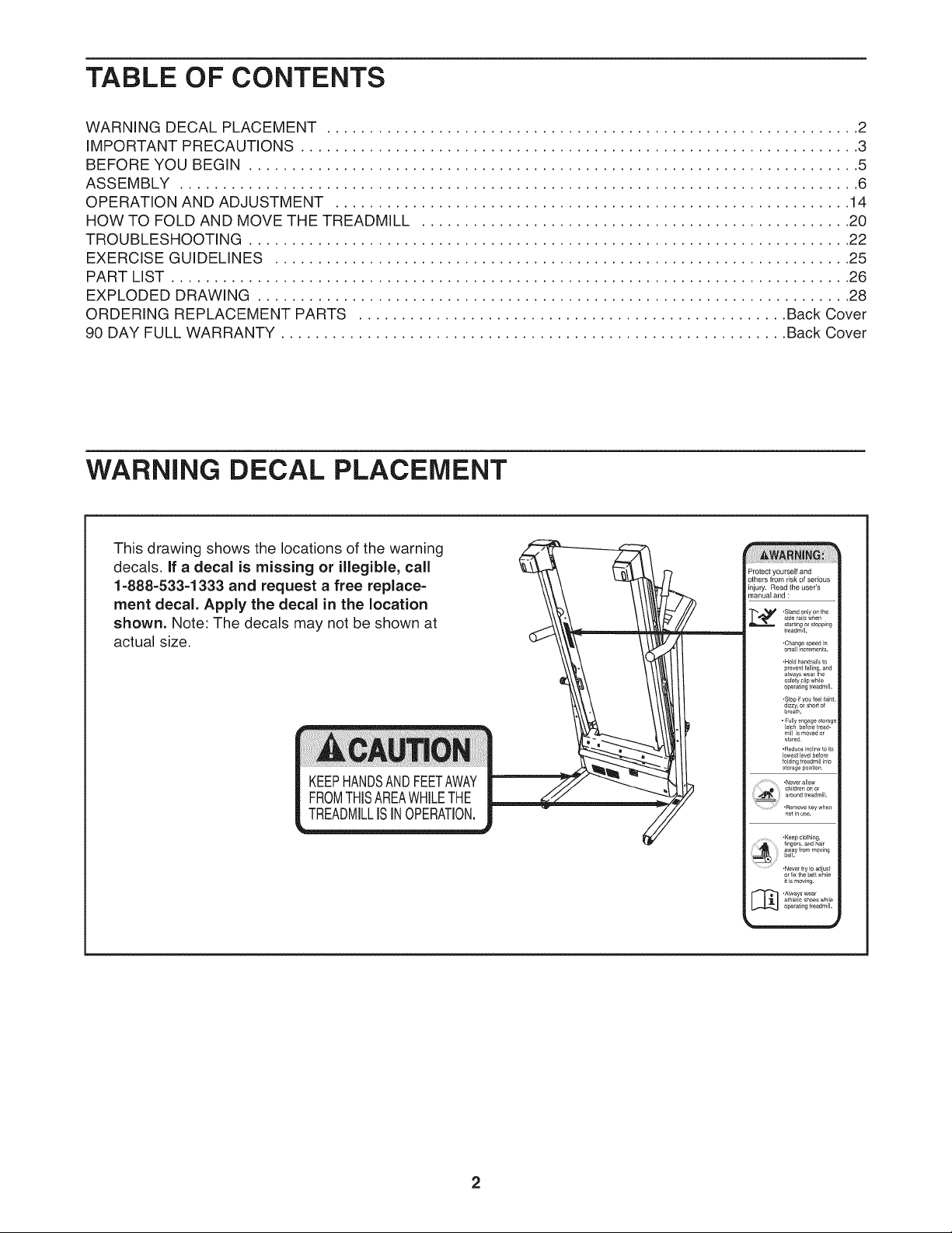
TABLE OF CONTENTS
WARNING DECAL PLACEMENT .............................................................. 2
IMPORTANT PRECAUTIONS ................................................................. 3
BEFORE YOU BEGIN ....................................................................... 5
ASSEMBLY ............................................................................... 6
OPERATION AND ADJUSTMENT ............................................................ 14
HOW TO FOLD AND MOVE THE TREADMILL .................................................. 20
TROUBLESHOOTING ...................................................................... 22
EXERCISE GUIDELINES ................................................................... 25
PART LIST ............................................................................... 26
EXPLODED DRAWING ..................................................................... 28
ORDERING REPLACEMENT PARTS .................................................. Back Cover
90 DAY FULL WARRANTY ........................................................... Back Cover
WARNING DECAL PLACEMENT
This drawing shows the locations of the warning
decals, if a decal is missing or illegible, call
1-888-533-1333 and request a free replace-
ment decal. Apply the decal in the location
shown. Note: The decals may not be shown at
actual size.
KEEPHANDSANDFEETAWAY
FROMTHISAREAWHILETHE
TREADMILLISINOPERATION.
_rotect yourself and
others from risk of serious
injury. Read the user's
manual and :
side rails when
•Stand only on the
.Hold handrails to
prevent falling, and
always weal the
safety clip while
operating t/eadm II.
.Stop if you feel fa_t,
dizzy, o[ short of
breath.
• Fully engage storage
latch belo[e tread-
mill _s moved or
stored
,Reduce incline to _ts
lowest level before
folding treadmill _nto
sto_age positbt,
•Never allow
cbildren oF or
•Remove key when
r_otEnuse.
•Keep clothing,
_yf........Jog
....... "Nevertrytoadiust
or lix the belt while
it _smovb_g.
athlel c shoes while
_ .Always wear
operating t[eadm_ll,
iMPORTANT PRECAUTIONS
WARNING: Toreducetheriskofserious njury,reada, mportantprecautionsand
structions in this manual and all warnings on your treadmill before using your treadmill. Sears as-
sumes no responsibility for personal injury or property damage sustained by or through the use of
this product.
Before beginning any exercise program, con-
sult your physician. This is especially impor-
tant for persons over age 35 or persons with
pre-existing health problems.
2. it is the responsibility of the owner to ensure
that all users of this treadmill are adequately
informed of all warnings and precautions.
3. Use the treadmill only as described.
.
Place the treadmill on a level surface, with at
least 8 ft. (2.4 m) of clearance behind it and 2
ft. (0.6 m) on each side. Do not place the
treadmill on any surface that blocks air open-
ings. To protect the floor or carpet from dam-
age, place a mat under the treadmill.
5. Keep the treadmill indoors, away from mois-
ture and dust. Do not put the treadmill in a
garage or covered patio, or near water.
6. Do not operate the treadmill where aerosol
products are used or where oxygen is being
administered.
7. Keep children under age 12 and pets away
from the treadmill at all times.
8. The treadmill should not be used by persons
weighing more than 250 Ibs. (113 kg).
9. Never allow more than one person on the
treadmill at a time.
10. Wear appropriate exercise clothes when
using the treadmill. Do not wear loose clothes
that could become caught in the treadmill.
Athletic support clothes are recommended for
both men and women. Always wear athletic
shoes; never use the treadmill with bare feet,
wearing only stockings, or in sandals.
11. When connecting the power cord (see page 14),
plug the power cord into a surge suppressor
(not included) and plug the surge suppressor
into a grounded circuit capable of carrying 15
or more amps. No other appliance should be on
the same circuit. Do not use an extension cord.
12.
Use only a single-outlet surge suppressor that
meets all of the specifications described on
page 14. To purchase a surge suppressor, see
your local Sears store or call the telephone
number on the back cover of this manual and
order part number 146148, or see your local
electronics store.
13.
Failure to use a properly functioning surge
suppressor could result in damage to the con-
trol system of the treadmill if the control sys-
tem is damaged, the walking belt may slow,
accelerate, or stop unexpectedly, which may
result in a fall and serious injury.
14.
Keep the power cord and the surge suppres-
sor away from heated surfaces.
15.
Never move the walking belt while the power
is turned off. Do not operate the treadmill if
the power cord or plug is damaged, or if the
treadmill is not working properly. (See TROU-
BLESHOOTING on page 22 if the treadmill is
not working properly.)
16.
Read, understand, and test the emergency
stop procedure before using the treadmi!l (see
HOW TO TURN ON THE POWER on page 16).
17.
Never start the treadmill while you are stand=
ing on the walking belt. Always hold the
handrails while using the treadmill
18.
The pulse sensor is not a medical device.
Various factors, including your movement,
may affect the accuracy of heart rate readings.
The pulse sensor is intended only as an exer-
cise aid in determining heart rate trends in
general.
19.The treadmill is capable of high speeds.
Adjust the speed in small increments to avoid
sudden jumps in speed.
20. Never leave the treadmill unattended while it
is running. Always remove the key, unplug
the power cord, and switch the reset/off cir-
cuit breaker to the off position when the
treadmill is not in use. (See the drawing on
page 5 for the location of the circuit breaker.)
21. Do not attempt to raise, lower, or move the
treadmill until it is properly assembled. (See
ASSEMBLY on page 6 and HOW TO FOLD
AND MOVE THE TREADMILL on page 20.)
You must be able to safely lift 45 Ibs. (20 kg)
to raise, lower, or move the treadmill.
22. When folding or moving the treadmill, make
sure that the storage latch is holding the
frame securely in the storage position.
23. Do not change the incline of the treadmill by
placing objects under the treadmill.
24.
inspect and properly tighten all parts of the
treadmill regularly.
25.
Never drop or insert any object into any
opening on the treadmill.
26.
This treadmill is intended for in-home use
only. Do not use this treadmill in a commer-
cial, rental, or institutional setting.
27.
DANGER: A waysunplugthepower
cord immediately after use, before cleaning
the treadmill, and before performing the main-
tenance and adjustment procedures de-
scribed in this manual. Never remove the
motor hood unless instructed to do so by an
authorized service representative. Servicing
other than the procedures in this manual
should be performed by an authorized service
representative only.
SAVE THESE
iNSTRUCTiONS
4
BEFORE YOU BEGIN
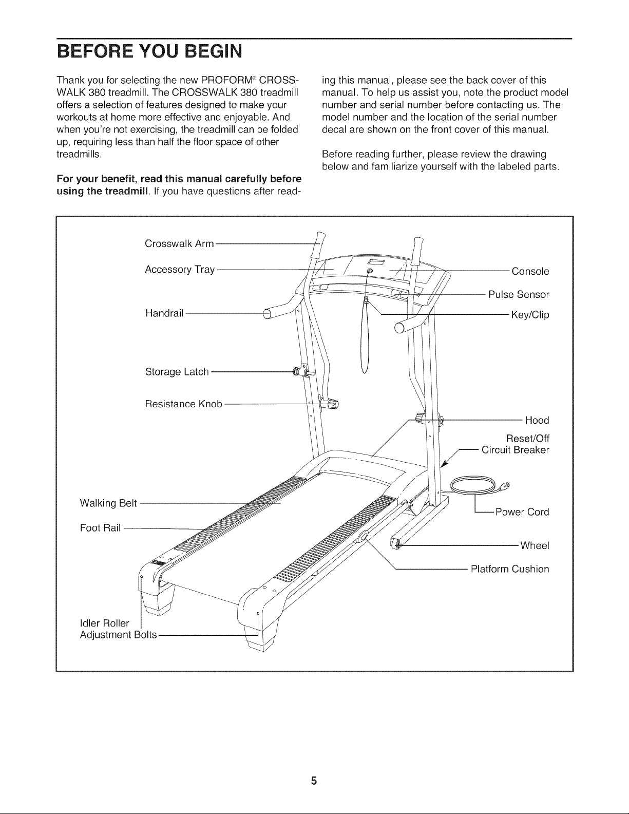
Thank you for selecting the new PROFORM ®CROSS-
WALK 380 treadmill. The CROSSWALK 380 treadmill
offers a selection of features designed to make your
workouts at home more effective and enjoyable. And
when you're not exercising, the treadmill can be folded
up, requiring less than half the floor space of other
treadmills.
For your benefit, read this manual carefully before
using the treadmill. If you have questions after read-
Crosswalk Arm
Accessory Tray
Handrail
Storage Latch
ing this manual, please see the back cover of this
manual. To help us assist you, note the product model
number and serial number before contacting us. The
model number and the location of the serial number
decal are shown on the front cover of this manual.
Before reading further, please review the drawing
below and familiarize yourself with the labeled parts.
Console
Pulse Sensor
Key/Clip
Resistance Knob
Walking Belt
Foot Rail
Idler Roller
Adjustment Bolts
Hood
Reset/Off
Circuit Breaker
-- Power Cord
Wheel
Platform Cushion
5
ASSEMBLY
Assembly requires two persons. Set the treadmill in a cleared area and remove all packing materials. Do not
dispose of the packing materials until assembly is completed. Note: The underside of the treadmill walking
belt is coated with high-performance lubricant. During shipping, a small amount of lubricant may be transferred to
the top of the walking belt or the shipping carton. This is a normal condition and does not affect treadmill perfor-
mance. If there is lubricant on top of the walking belt, simply wipe off the lubricant with a soft cloth and a mild,
non-abrasive cleaner.
Assembly requires the included hex_ and your own Phillips screwdriver _L_====_, adjustable
wrench _, scissors _=_, needlenose pliers _, and rubber mallet _.
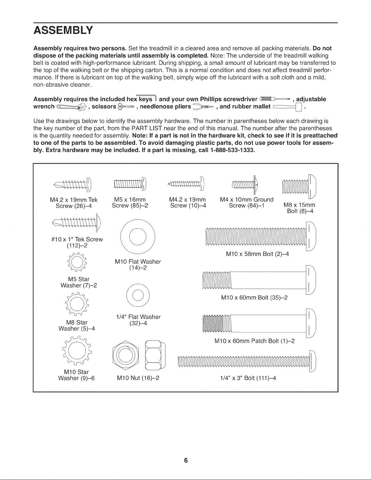
Use the drawings below to identify the assembly hardware. The number in parentheses below each drawing is
the key number of the part, from the PART LIST near the end of this manual. The number after the parentheses
is the quantity needed for assembly. Note: if a part is not in the hardware kit, check to see if it is preattached
to one of the parts to be assembled. To avoid damaging plastic parts, do not use power tools for assem-
bly. Extra hardware may be included, if a part is missing, call 1-888-533-1333.
M4.2 x 19mm Tek
Screw (26)-4
#10 x 1" Tek Screw
(112)-2
©
M5 Star
Washer (7)-2
M8 Star
Washer (5)-4
M10 Star
Washer (9)-6
M5 x 16mm M4.2 x 19mm M4 x 10mm Ground
Screw (85)-2 Screw (10)-4 Screw (84)-1 M8 x 15mm
Bolt (8)-4
M10 x 58mm Bolt (2)-4
M10 Flat Washer
(14)-2
M10 x 60mm Bolt (35)-2
1/4" Flat Washer
(32)-4
M10 x 60mm Patch Bolt (1)-2
M10 Nut (16)-2
1/4" x 3" Bolt (111)-4
6
.
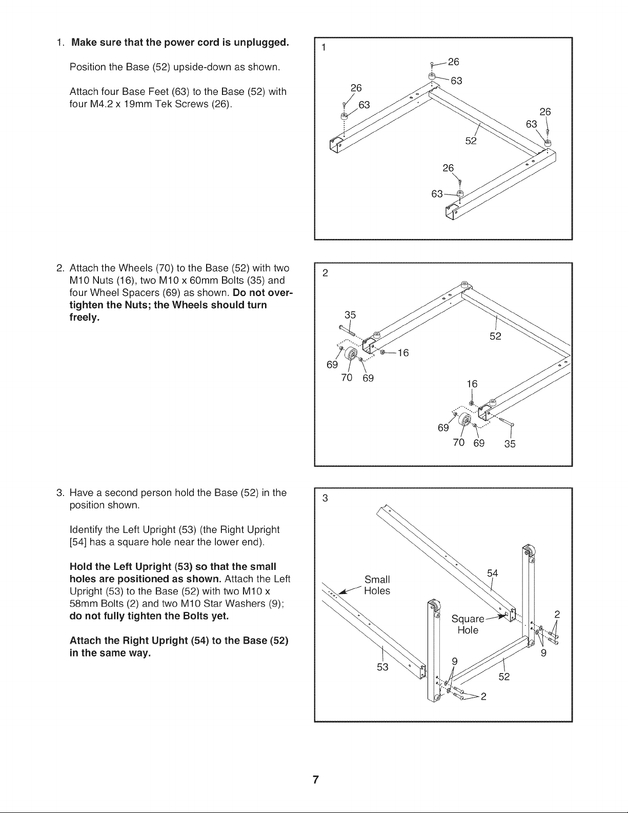
Make sure that the power cord is unplugged.
Position the Base (52) upside-down as shown.
Attach four Base Feet (63) to the Base (52) with
four M4.2 x 19mm Tek Screws (26).
2. Attach the Wheels (70) to the Base (52) with two
M10 Nuts (16), two M10 x 60mm Bolts (35) and
four Wheel Spacers (69) as shown, Do not over-
tighten the Nuts; the Wheels should turn
freely.
26
26
52
26
2
35
52
6
69
16
3. Have a second person hold the Base (52) in the
position shown.
Identify the Left Upright (53) (the Right Upright
[54] has a square hole near the lower end).
Hold the Left Upright (53) so that the small
holes are positioned as shown. Attach the Left
Upright (53) to the Base (52) with two M10 x
58mm Bolts (2) and two M10 Star Washers (9);
do not fully tighten the Bolts yet.
Attach the Right Upright (54) to the Base (52)
in the same way.
69
70 69
35
3
Small
54
Holes
Sql
Hole
2
A
9
53
52
7
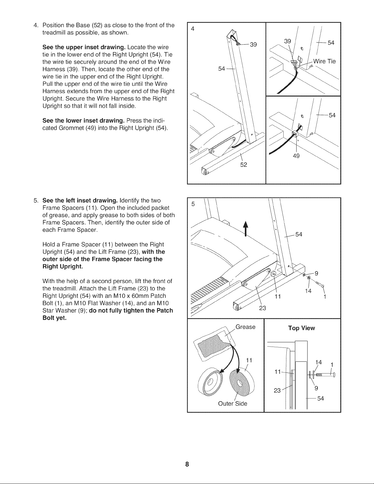
Position the Base (52) as close to the front of the
4. 4
treadmill as possible, as shown.
See the upper inset drawing. Locate the wire
tie in the lower end of the Right Upright (54). Tie
the wire tie securely around the end of the Wire
Harness (39). Then, locate the other end of the
wire tie in the upper end of the Right Upright.
Pull the upper end of the wire tie until the Wire
Harness extends from the upper end of the Right
Upright. Secure the Wire Harness to the Right
Upright so that it will not fall inside.
See the lower inset drawing. Press the indi-
cated Grommet (49) into the Right Upright (54).
.
See the left inset drawing. Identify the two
Frame Spacers (11). Open the included packet
of grease, and apply grease to both sides of both
Frame Spacers. Then, identify the outer side of
each Frame Spacer.
39
Tie
54
49
52
5 /'
Hold a Frame Spacer (11) between the Right
Upright (54) and the Lift Frame (23), with the
outer side of the Frame Spacer facing the
Right Upright.
With the help of a second person, lift the front of
the treadmill. Attach the Lift Frame (23) to the
Right Upright (54) with an M10 x 60mm Patch
Bolt (1), an M10 Flat Washer (14), and an M10
Star Washer (9); do not fully tighten the Patch
Bolt yet.
/
Outer Side
1 1
Top View
/
23 /
[--54
9
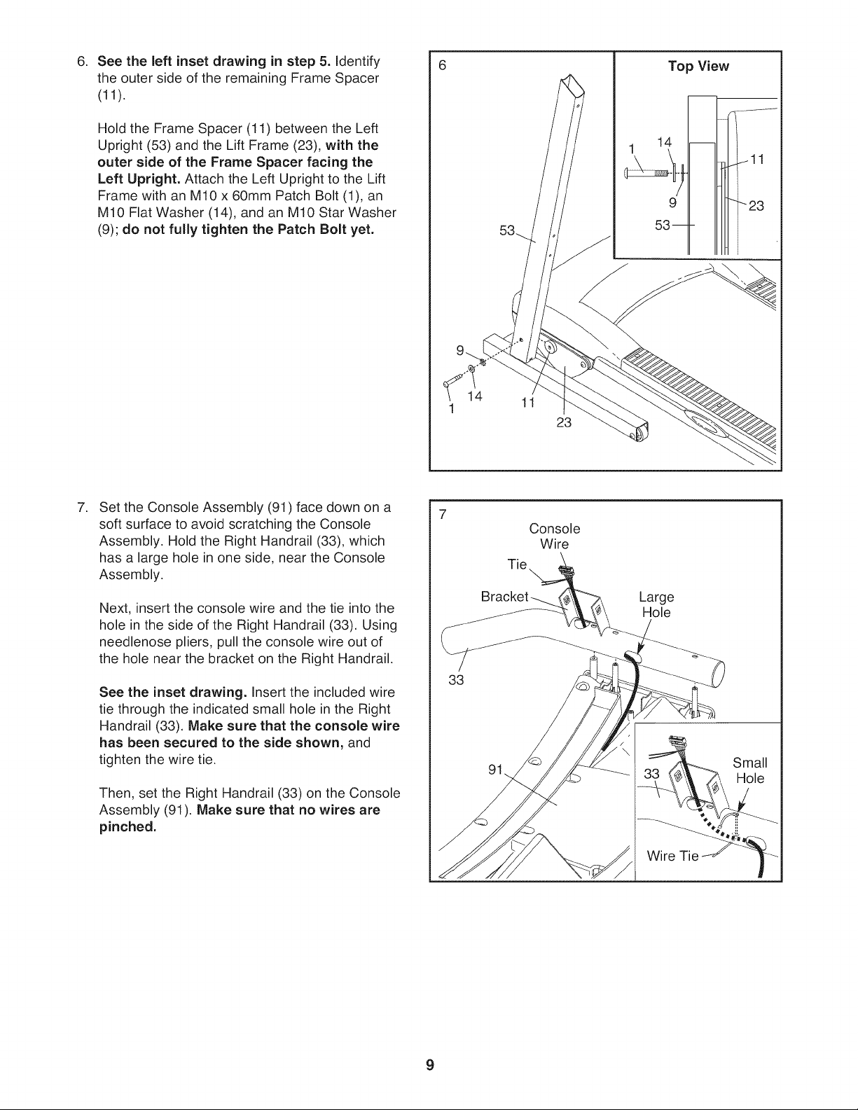
.
See the left inset drawing in step 5. identify
the outer side of the remaining Frame Spacer
(11).
Hold the Frame Spacer (11) between the Left
Upright (53) and the Lift Frame (23), with the
outer side of the Frame Spacer facing the
Left Upright. Attach the Left Upright to the Lift
Frame with an M10 x 60mm Patch Bolt (1), an
M10 Flat Washer (14), and an M10 Star Washer
(9); do not fully tighten the Patch Bolt yet.
Top View
.
Set the Console Assembly (91) face down on a
soft surface to avoid scratching the Console
Assembly. Hold the Right Handrail (33), which
has a large hole in one side, near the Console
Assembly.
Next, insert the console wire and the tie into the
hole in the side of the Right Handrail (33). Using
needlenose pliers, pull the console wire out of
the hole near the bracket on the Right Handrail.
See the inset drawing, insert the included wire
tie through the indicated small hole in the Right
Handrail (33). Make sure that the console wire
has been secured to the side shown, and
tighten the wire tie.
Then, set the Right Handrail (33) on the Console
Assembly (91). Make sure that no wires are
pinched.
33
14
91
11
23
Console
Wire
Tie\
Large
Hole
Small
Hole
Wire Tie
9
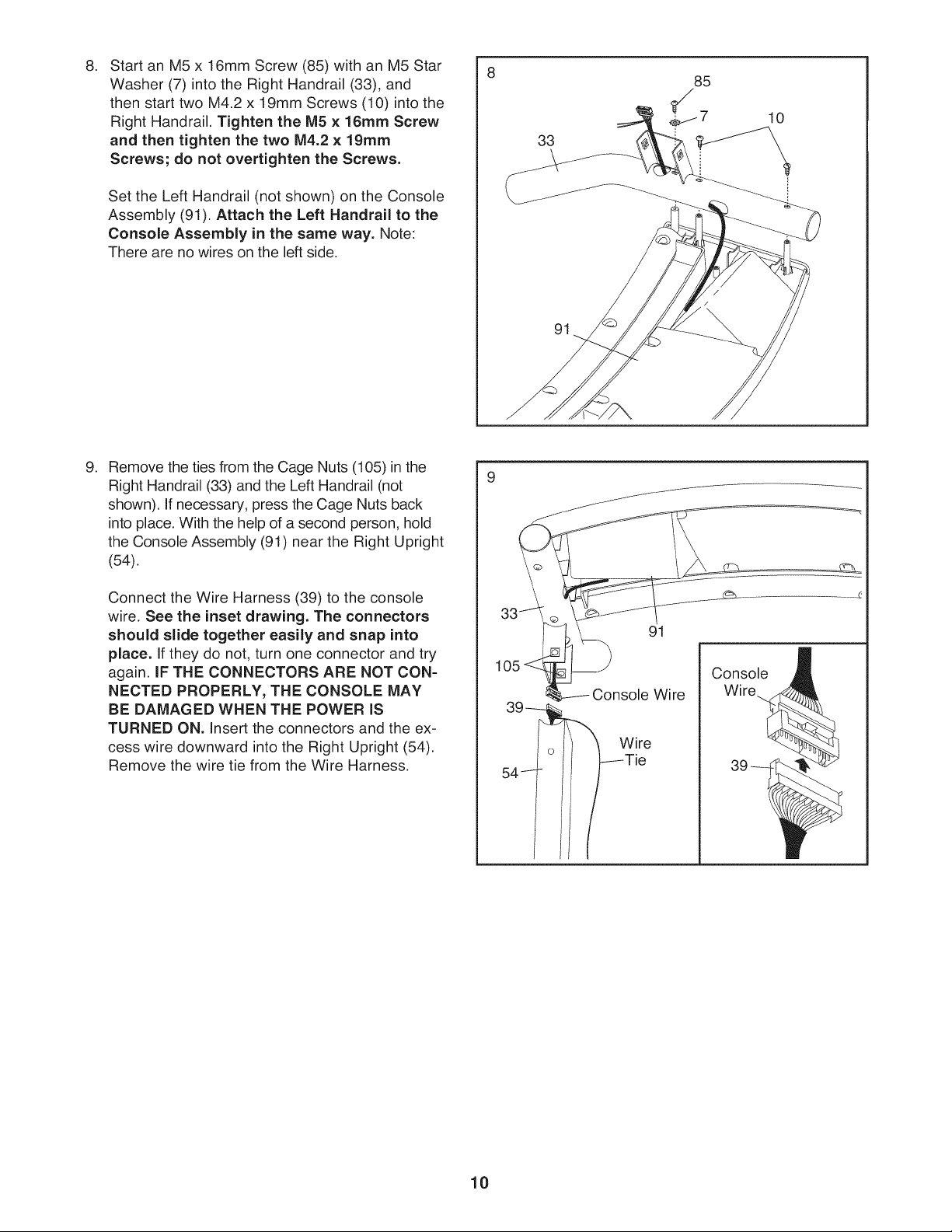
.
Start an M5 x 16mm Screw (85) with an M5 Star
Washer (7) into the Right Handrail (33), and
then start two M4.2 x 19mm Screws (10) into the
Right Handrail. Tighten the M5 x 16ram Screw
and then tighten the two IVl4.2x 19ram
Screws; do not overtighten the Screws.
Set the Left Handrail (not shown) on the Console
Assembly (91). Attach the Left Handrail to the
Console Assembly in the same way. Note:
There are no wires on the left side.
.
Remove the ties from the Cage Nuts (105) in the
Right Handrail (33) and the Left Handrail (not
shown). If necessary, press the Cage Nuts back
into place. With the help of a second person, hold
the Console Assembly (91) near the Right Upright
(54).
33
91
85
$7
10
Connect the Wire Harness (39) to the console
wire. See the inset drawing. The connectors
should slide together easily and snap into
place. Ifthey do not, turn one connector and try
again. IF THE CONNECTORS ARE NOT CON-
NECTED PROPERLY, THE CONSOLE MAY
BE DAMAGED WHEN THE POWER iS
TURNED ON. Insert the connectors and the ex-
cess wire downward into the Right Upright (54).
Remove the wire tie from the Wire Harness.
33
Console
Wire Wire..
Wire
/Tie
10