

Proform 831247233 Owner’s Manual
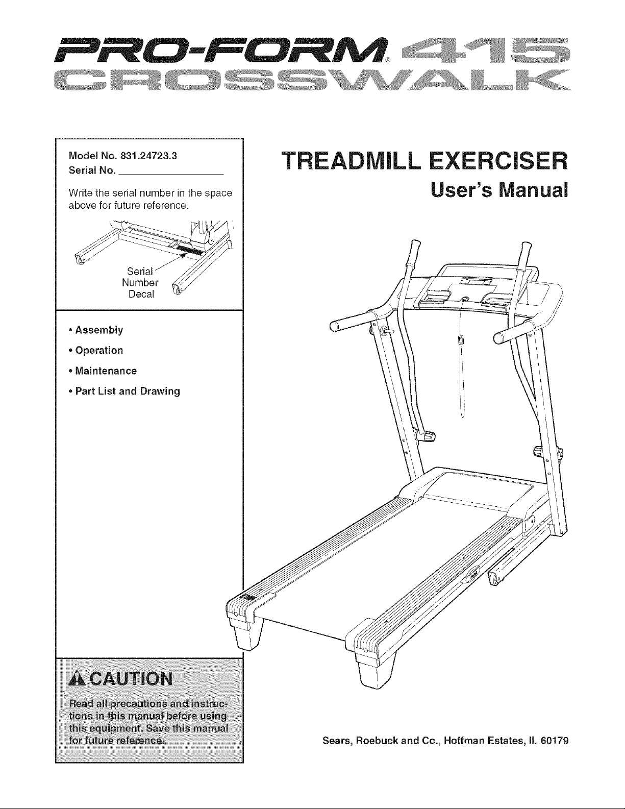
Model No. 831.24723.3
Serial No.
TR LL EXERCIS
Write the serial number in the space
above for future reference.
Number
Decal
, Assembly
, Operation
,, Maintenance
, Part List and Drawing
User's Manual
Sears, Roebuck and Co., Hoffman Estates, IL 60179
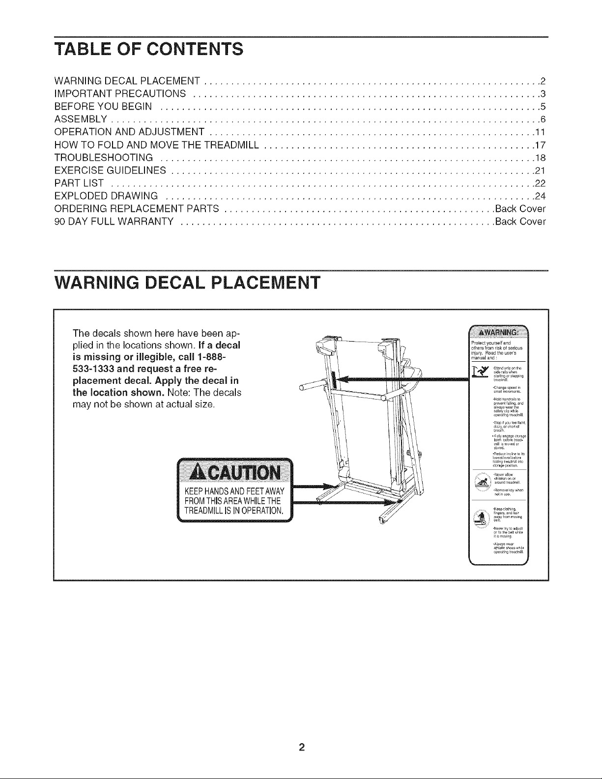
TABLE OF CONTENTS
WARNING DECAL PLACEMENT .............................................................. 2
IMPORTANT PRECAUTIONS ................................................................ 3
BEFORE YOU BEGIN ...................................................................... 5
ASSEMBLY ............................................................................... 6
OPERATION AND ADJUSTMENT ............................................................ 11
HOW TO FOLD AND MOVE THE TREADMILL .................................................. 17
TROUBLESHOOTING ..................................................................... 18
EXERCISE GUIDELINES ................................................................... 21
PART LIST .............................................................................. 22
EXPLODED DRAWING .................................................................... 24
ORDERING REPLACEMENT PARTS .................................................. Back Cover
90 DAY FULL WARRANTY .......................................................... Back Cover
WARNING DECAL PLACEMENT
The decals shown here have been ap-
plied in the locations shown. If a decal
is missing or illegible, call 1=888=
533=1333 and request a free re=
placement decal. Apply the decal in
the location shown. Note: The decals
may not be shown at actual size.
KEEPHANDSANDFEETAWAY
FROMTHiSAREAWHILETHE
TREADMILLISINOPERATION.
Protect yourself and
others _rom risk of serious
in uly. Read the user's
mar,ua and :
iMPORTANT PRECAUTIONS
4
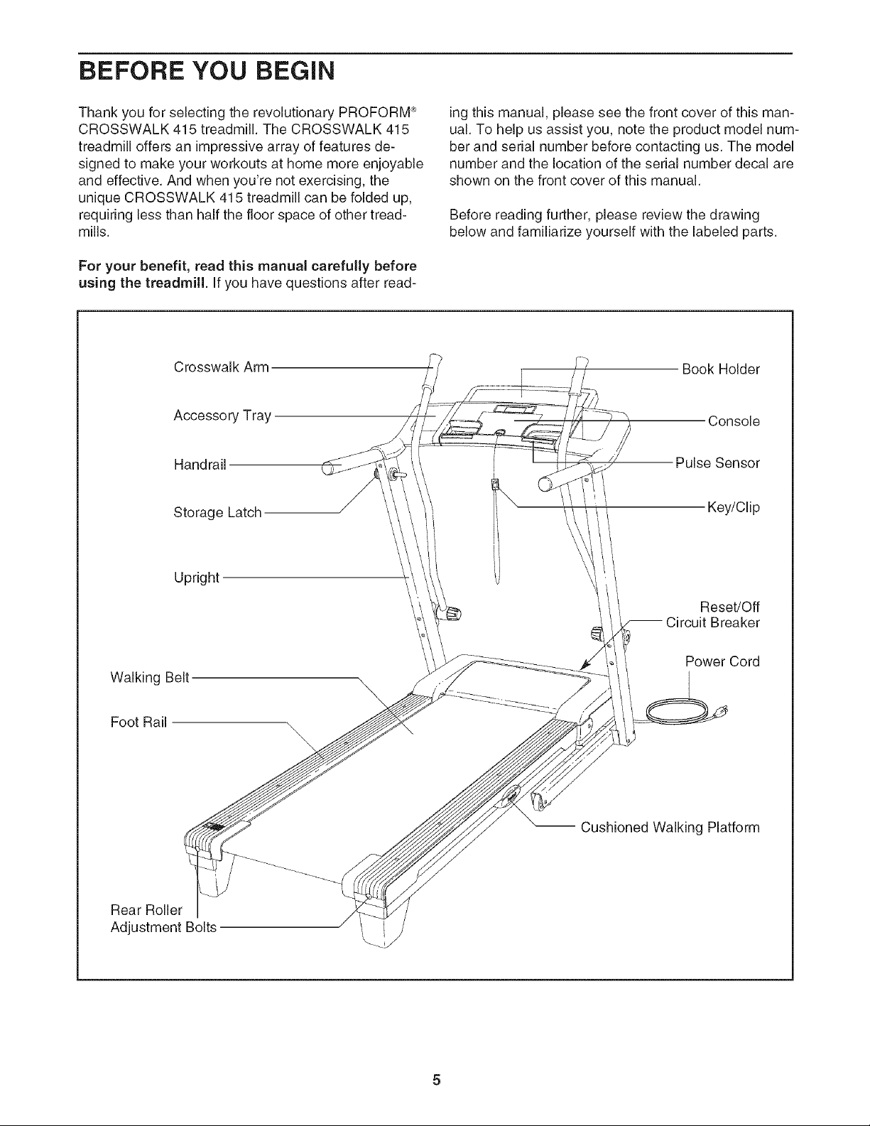
BEFORE YOU BEGIN
Thank you for selecting the revolutionary PROFORM _
CROSSWALK 415 treadmill. The CROSSWALK 415
treadmill offers an impressive array of features de-
signed to make your workouts at home more enjoyable
and effective. And when you're not exercising, the
unique CROSSWALK 415 treadmill can be folded up,
requiring less than half the floor space of other tread-
mills.
For your benefit, read this manual carefully before
using the treadmill. If you have questions after read-
Crosswalk Arm
Accessory Tray
Handrail
Storage Latch
ing this manual, please see the front cover of this man-
ual. To help us assist you, note the product model num-
ber and serial number before contacting us. The model
number and the location of the serial number decal are
shown on the front cover of this manual.
Before reading further, please review the drawing
below and familiarize yourself with the labeled parts.
Book Holder
Console
Pulse Sensor
Key/Clip
Upright
Walking Belt
Foot Rail
Rear Roller
Adjustment Bolts
Reset/Off
Breaker
Power Cord
\
Cushioned Walking Platform

ASSEMBLY
Assembly requires two persons. Set the treadmill in a cleared area and remove all packing materials. Do not
dispose of the packing materials until assembly is completed. Note: The underside of the treadmill walking belt is
coated with high-performance lubricant. During shipping, a small amount of lubricant may be transferred to the
top of the walking belt or the shipping carton. This is a normal condition and does not affect treadmill perfor-
mance. If there is lubricant on top of the walking belt, simply wipe off the lubricant with a soft cloth and a mild,
non-abrasive cleaner.
Assembly requires the included he_ and your own Phillips screwdriver _ and
adjustable wrench _._.
Use the drawings below to identify the assembly hardware. The number in parentheses below each drawing is
the key number of the part, from the PART LIST near the end of this manual. The number after the parentheses
is the quantity needed for assembly. Note: If a part is not in the parts bag, check to see if it is preattached to
one of the parts to be assembled. Extra hardware may be included. If a part is missing, call 1=888=533=
1333. To avoid damaging plastic parts, do not use power tools for assembly.
1/2" Screw M4 x 25mm
(22)-1 Screw (2)-4
M8 Star M10 Star
Washer (10)-4 Washer (8)-8 \"_- .....
Base Pad Spacer
(104)-2
M4 x 19mm
Screw (1)-6
M8 x 25mm Bolt (6)-4
1/4" Washer
(9)-4
Bolt Spacer (79)-4
Make sure that the power cord is unplugged.
With the help of a second person, carefully tip
the treadmill onto its left side. Partially fold the
Frame (48) so that the treadmill is more stable;
do not fully fold the Frame yet.
Remove and discard the two indicated bolts (A)
and the shipping bracket (B).
Cut the tie securing the Upright Wire (77) to the
Base (85). Locate the tie in the indicated hole in
the Base, and use the tie to pull the Upright Wire
out of the hole.
Attach a Base Pad (81) to the Base (85) in the
location shown with a Base Pad Spacer (104)
and an M4 x 25mm Screw (2). Then, attach an-
other Base Pad (81) with only a Screw (2).
1/4" x 3 1/2" Bolt (4)-4
M10 x 96mm Bolt (5)-4
Tie 77
48
104
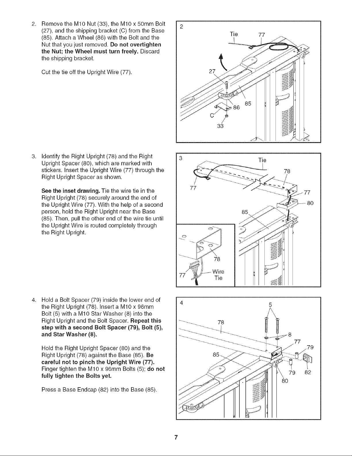
RemovetheMIONut(33),theMIOx50mmBolt
2. 2
(27),andtheshippingbracket(C)fromtheBase
(85).AttachaWheel(86)withtheBoltandthe
Nutthatyoujustremoved.Donotovertighten
theNut;theWheelmustturnfreely.Discard
theshippingbracket.
Tie
77
CutthetieofftheUprightWire(77).
Identify the Right Upright (78) and the Right
Upright Spacer (80), which are marked with
stickers. Insert the Upright Wire (77) through the
Right Upright Spacer as shown.
See the inset drawing. Tie the wire tie in the
Right Upright (78) securely around the end of
the Upright Wire (77). With the help of a second
person, hold the Right Upright near the Base
(85). Then, pull the other end of the wire tie until
the Upright Wire is routed completely through
the Right Upright.
77
27
\
33
Tie
78
Hold a Bolt Spacer (79) inside the lower end of
the Right Upright (78). Insert a MIO x 96mm
Bolt (5) with a MIO Star Washer (8) into the
Right Upright and the Bolt Spacer. Repeat this
step with a second Bolt Spacer (79), Bolt (5),
and Star Washer (8).
Hold the Right Upright Spacer (80) and the
Right Upright (78) against the Base (85). Be
careful not to pinch the Upright Wire (77).
Finger tighten the MIO x 96mm Bolts (5); do not
fully tighten the Bolts yet.
Press a Base Endcap (82) into the Base (85).
_ 78
_8 77
79
8O
82
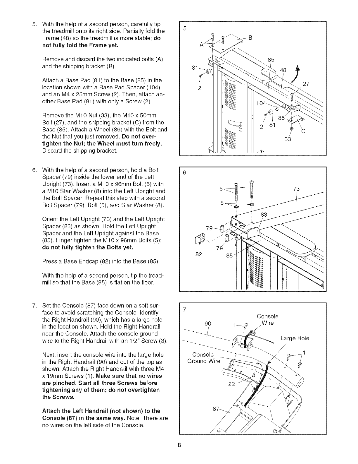
5.
With the help of a second person, carefully tip
the treadmill onto its right side. Partially fold the
Frame (48) so the treadmill is more stable; do
not fully fold the Frame yet.
5
Remove and discard the two indicated bolts (A)
and the shipping bracket (B).
Attach a Base Pad (81) to the Base (85) in the
location shown with a Base Pad Spacer (104)
and an M4 x 25mm Screw (2). Then, attach an-
other Base Pad (81) with only a Screw (2).
Remove the MIO Nut (33), the MIO x 50mm
Bolt (27), and the shipping bracket (C) from the
Base (85). Attach a Wheel (86) with the Bolt and
the Nut that you just removed. Do not over-
tighten the Nut; the Wheel must turn freely.
Discard the shipping bracket.
With the help of a second person, hold a Bolt
Spacer (79) inside the lower end of the Left
Upright (73). insert a MIO x 96mm Bolt (5) with
a MIO Star Washer (8) into the Left Upright and
the Bolt Spacer. Repeat this step with a second
Bolt Spacer (79), Bolt (5), and Star Washer (8).
Orient the Left Upright (73) and the Left Upright
Spacer (83) as shown. Hold the Left Upright
Spacer and the Left Upright against the Base
(85). Finger tighten the MIO x 96mm Bolts (5);
do not fully tighten the Bolts yet.
Press a Base Endcap (82) into the Base (85).
85
27
C
33
73
79
82
With the help of a second person, tip the tread-
mill so that the Base (85) is flat on the floor.
Set the Console (87) face down on a soft sur-
face to avoid scratching the Console. Identify
the Right Handrail (90), which has a large hole
in the location shown. Hold the Right Handrail
near the Console. Attach the console ground
wire to the Right Handrail with an 1/2" Screw (3).
Next, insert the console wire into the large hole
in the Right Handrail (90) and out of the top as
shown. Attach the Right Handrail with three M4
x 19mm Screws (1). Make sure that no wires
are pinched. Start all three Screws before
tightening any of them; do not overtighten
the Screws.
Attach the Left Handrail (not shown) to the
Console (87) in the same way. Note: There are
no wires on the left side of the Console.
8
Ground
9O
/
Console
Wire
Large Hole
/
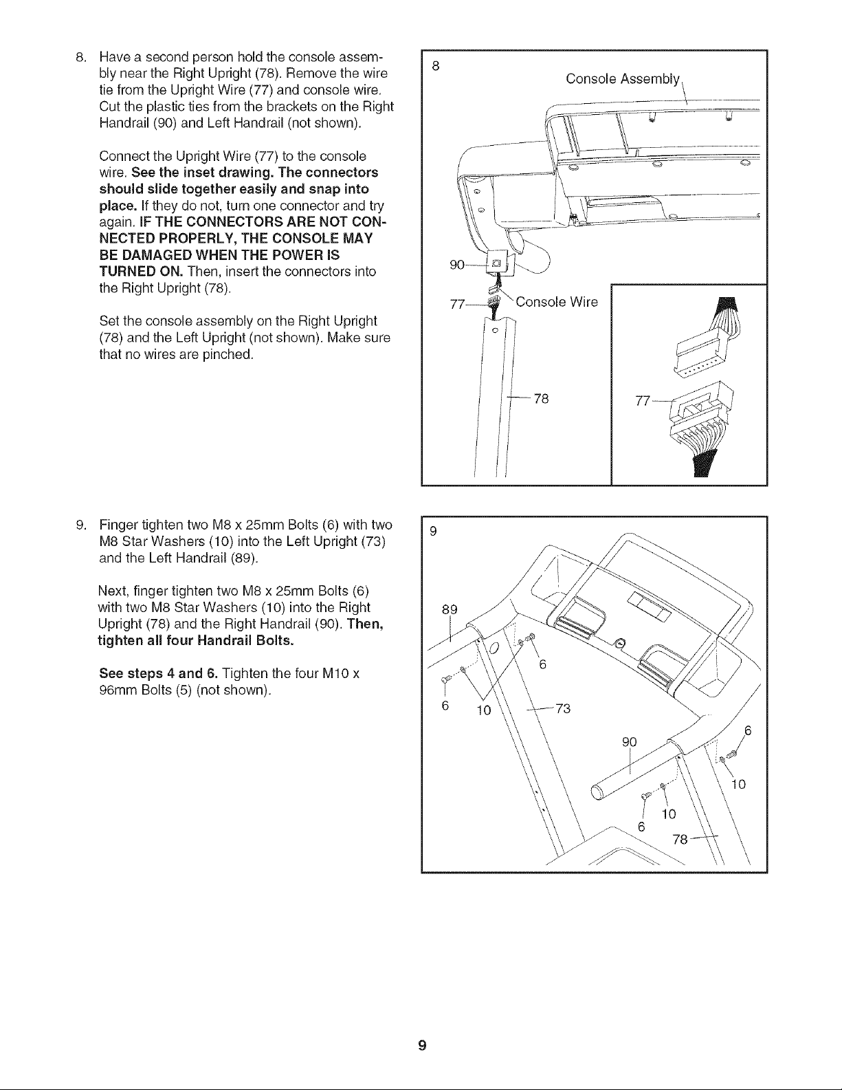
Have a second person hold the console assem-
bly near the Right Upright (78). Remove the wire
tie from the Upright Wire (77) and console wire.
Cut the plastic ties from the brackets on the Right
Handrail (90) and Left Handrail (not shown).
Connect the Upright Wire (77) to the console
wire. See the inset drawing. The connectors
should slide together easily and snap into
place. If they do not, turn one connector and try
again. IF THE CONNECTORS ARE NOT CON=
NECTED PROPERLY, THE CONSOLE MAY
BE DAMAGED WHEN THE POWER iS
TURNED ON. Then, insert the connectors into
the Right Upright (78).
Set the console assembly on the Right Upright
(78) and the Left Upright (not shown). Make sure
that no wires are pinched.
f Console Assembly I
Finger tighten two M8 x 25mm Bolts (6) with two
M8 Star Washers (10) into the Left Upright (73)
and the Left Handrail (89).
Next, finger tighten two M8 x 25mm Bolts (6)
with two M8 Star Washers (10) into the Right
Upright (78) and the Right Handrail (90). Then,
tighten all four Handrail Bolts.
See steps 4 and 6. Tighten the four MIO x
96mm Bolts (5) (not shown).
89
6 10
 Loading...