

Pro-Form 831.21942.1 User Manual
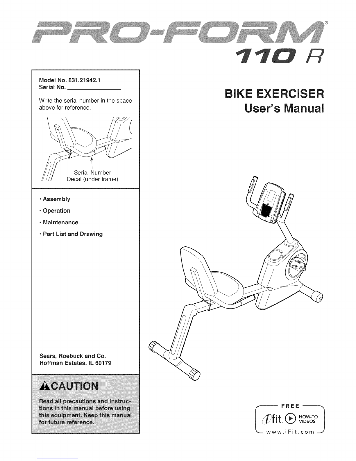
Model No. 831.21942.1
Serial No.
Write the serial number in the space
above for reference.
t
Serial Number
Decal (under frame)
•Assembly
• Operation
• Maintenance
g
BIKE EXERCISER
User's Manual
• Part List and Drawing
Sears, Roebuck and Co.
Hoffman Estates, IL 60179
_w FREE
t Q v",°Ew&°I
.iFit.com ._
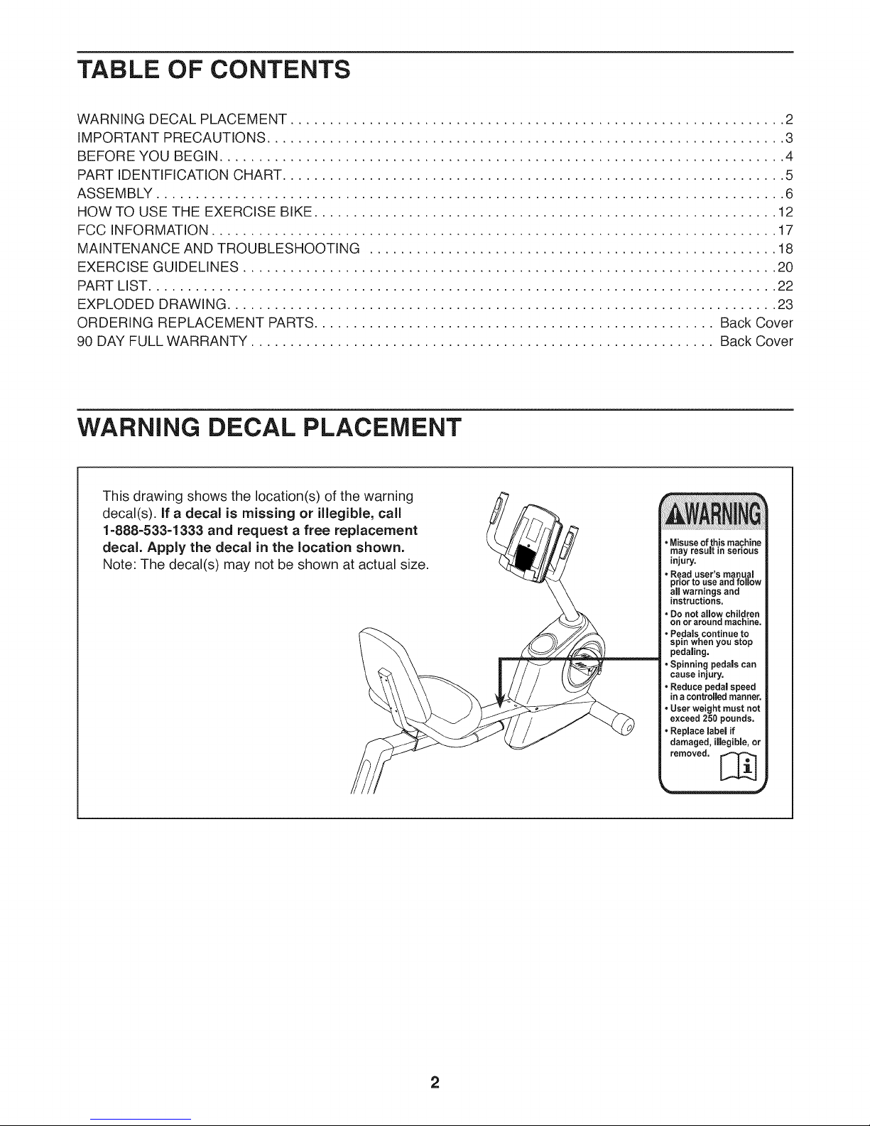
TABLE OF CONTENTS
WARNING DECAL PLACEMENT ............................................................... 2
IMPORTANT PRECAUTIONS .................................................................. 3
BEFORE YOU BEGIN ........................................................................ 4
PART IDENTIFICATION CHART ................................................................ 5
ASSEMBLY ................................................................................ 6
HOW TO USE THE EXERCISE BIKE ........................................................... 12
FCC INFORMATION ........................................................................ 17
MAINTENANCE AND TROUBLESHOOTING .................................................... 18
EXERCISE GUIDELINES .................................................................... 20
PART LIST................................................................................ 22
EXPLODED DRAWING ...................................................................... 23
ORDERING REPLACEMENT PARTS ................................................... Back Cover
90 DAY FULL WARRANTY ........................................................... Back Cover
WARNING DECAL PLACEMENT
This drawing shows the location(s) of the warning
decal(s), if a decal is missing or illegible, call
1-888-533-1333 and request a free replacement
decal. Apply the decal in the location shown.
Note: The decal(s) may not be shown at actual size.
• Do not allow children
on or around machine.
=Pedals continue to
spin when you stop
pedaling.
• Spinning pedals can
cause injury.
• Reduce pedal speed
in acontrolled manner.
• User weight must not
exceed 250 pounds.
• Replace label if
damaged, illegible, or
removed. [_
2
iMPORTANT PRECAUTIONS
WARNING: Toreducetheriskofseriousinjury,readallimportantprecautionsand
instructions in this manual and all warnings on your exercise bike before using your exercise bike.
Sears assumes no responsibility for personal injury or property damage sustained by or through the
use of this product.
1. Before beginning any exercise program, 9.
consult your physician. This is especially
important for persons over age 35 or per-
sons with pre-existing health problems.
2. Use the exercise bike only as described in 10.
this manual.
,
it is the responsibility of the owner to ensure
that all users of the exercise bike are ade-
quately informed of all precautions.
11.
=
The exercise bike is intended for home use
only. Do not use the exercise bike in a com-
mercial, rental, or institutiona! setting.
12.
.
Keep the exercise bike indoors, away from
moisture and dust. Do not put the exercise
bike in a garage or covered patio, or near
water.
.
Place the exercise bike on a level surface,
13.
with a mat beneath it to protect the floor or
carpet. Make sure that there is at least 2 ft.
14.
(0.6 m) of clearance around the exercise bike.
.
Inspect and properly tighten all parts regu-
larly. Replace any worn parts immediately.
Wear appropriate clothes while exercising;
do not wear loose clothes that could become
caught on the exercise bike. Always wear
athletic shoes for foot protection.
The heart rate monitor is not a medical
device. Various factors may affect the accu-
racy of heart rate readings. The heart rate
monitor is intended only as an exercise aid
in general.
The exercise bike should not be used by
persons weighing more than 250 Ibs.
(113 kg).
Always keep your back straight while using
the exercise bike; do not arch your back.
The exercise bike does not have a freewheel;
the pedals will continue to move until the
flywheel stops. Reduce your pedaling speed
in a controlled way.
Over exercising may result in serious injury
or death, if you feel faint or if you experience
pain while exercising, stop immediately and
cool down.
8. Keep children under age 12 and pets away
from the exercise bike at all times.
3
BEFORE YOU BEGIN
Thank you for selecting the new PROFORM '_'110
R exercise bike. Cycling is an effective exercise for
increasing cardiovascular fitness, building endurance,
and toning the body. The 110 R exercise bike provides
a selection of features designed to make your workouts
at home more effective and enjoyable.
For your benefit, read this manual carefully before
you use the exercise bike. If you have questions after
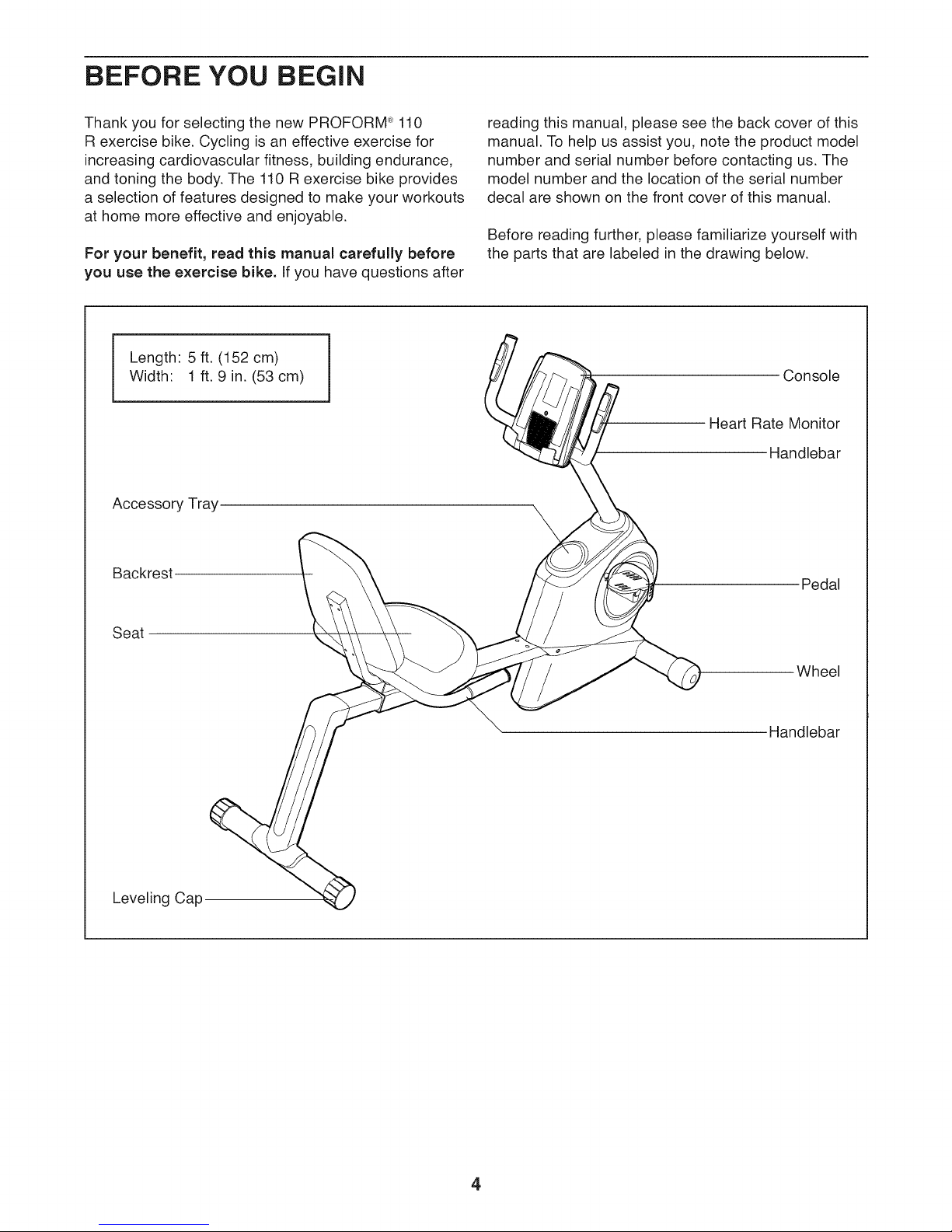
Length: 5 ft. (152 cm)
Width: 1 ft. 9 in. (53 cm)
Accessory Tray
Backrest
reading this manual, please see the back cover of this
manual. To help us assist you, note the product model
number and serial number before contacting us. The
model number and the location of the serial number
decal are shown on the front cover of this manual.
Before reading further, please familiarize yourself with
the parts that are labeled in the drawing below.
Console
Heart Rate Monitor
Handlebar
\
Pedal
Seat
Leveling Cap
Wheel
Handlebar
4
PART iDENTiFiCATiON CHART
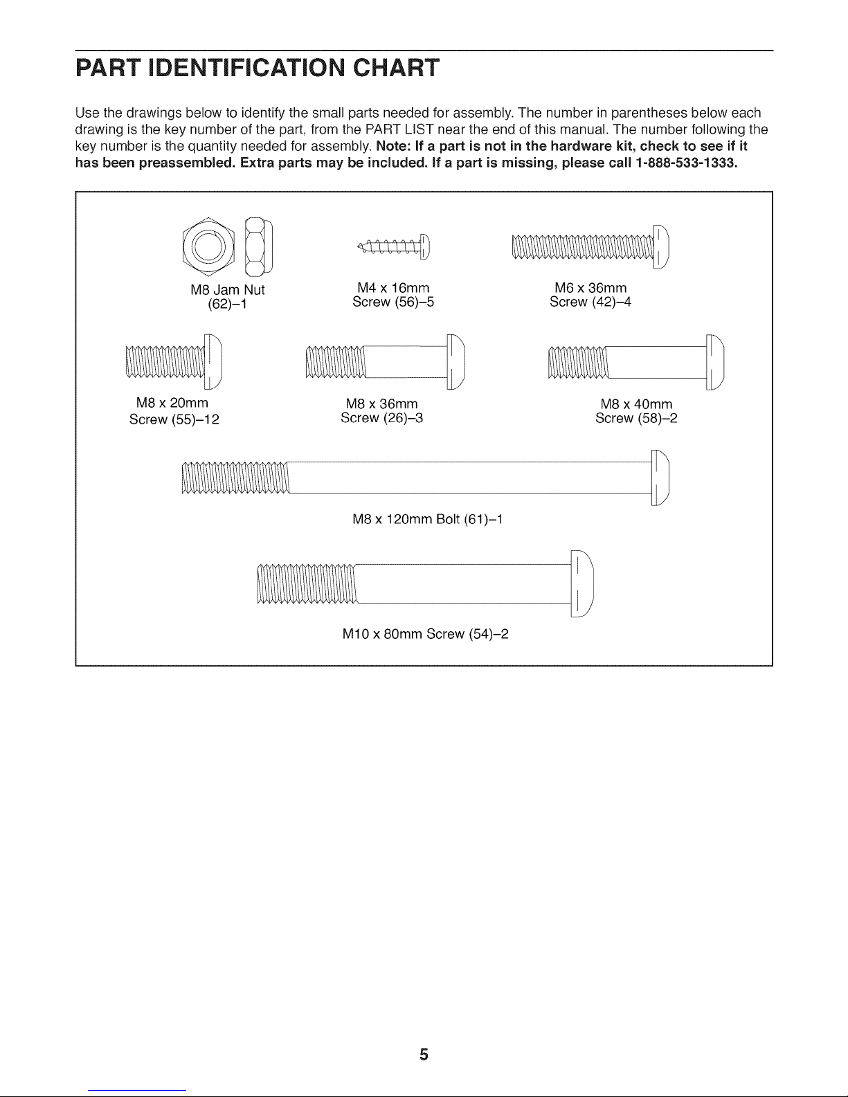
Use the drawings below to identify the small parts needed for assembly. The number in parentheses below each
drawing is the key number of the part, from the PART LIST near the end of this manual. The number following the
key number is the quantity needed for assembly. Note: If a part is not in the hardware kit, check to see if it
has been preassembled. Extra parts may be included, if a part is missing, please call 1-888=533=1333.
M8 Jam Nut
M8 x 20mm
Screw (55)-12
(62)-1
M4 x 16mm M6 x 36mm
Screw (56)-5 Screw (42)-4
M8 x 36mm
Screw (26)-3
M8 x 120mm Bolt (61)-1
M10 x 80mm Screw (54)-2
M8 x 40mm
Screw (58)-2
5
ASSEMBLY
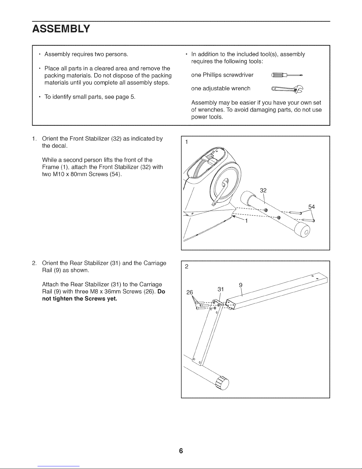
Assembly requires two persons.
Place all parts in a cleared area and remove the
packing materials. Do not dispose of the packing
materials until you complete all assembly steps.
To identify small parts, see page 5.
.
Orient the Front Stabilizer (32) as indicated by
the decal.
While a second person lifts the front of the
Frame (1), attach the Front Stabilizer (32) with
two M10 x 80mm Screws (54).
In addition to the included tool(s), assembly
requires the following tools:
one Phillips screwdriver (E_C:_=====_
one adjustable wrench
Assembly may be easier if you have your own set
of wrenches. To avoid damaging parts, do not use
power tools.
32
54
.
Orient the Rear Stabilizer (31) and the Carriage
Rail (9) as shown.
Attach the Rear Stabilizer (31) to the Carriage
Rail (9) with three M8 x 36mm Screws (26). Do
not tighten the Screws yet.
26
31
9
6
.
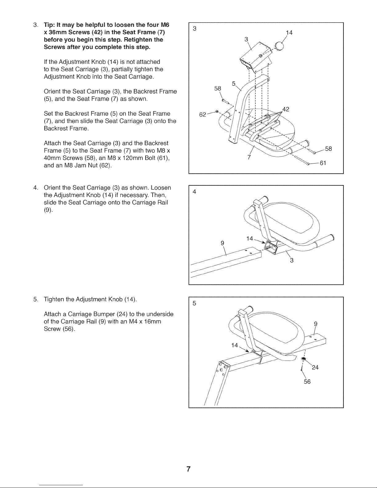
Tip: It may be helpful to loosen the four M6
× 36ram Screws (42) in the Seat Frame (7)
before you begin this step. Retighten the
Screws after you complete this step.
If the Adjustment Knob (14)is not attached
to the Seat Carriage (3), partially tighten the
Adjustment Knob into the Seat Carriage.
14
3
Orient the Seat Carriage (3), the Backrest Frame
(5), and the Seat Frame (7) as shown.
Set the Backrest Frame (5) on the Seat Frame
(7), and then slide the Seat Carriage (3) onto the
Backrest Frame.
Attach the Seat Carriage (3) and the Backrest
Frame (5) to the Seat Frame (7) with two M8 x
40mm Screws (58), an M8 x 120mm Bolt (61),
and an M8 Jam Nut (62).
.
Orient the Seat Carriage (3) as shown. Loosen
the Adjustment Knob (14) if necessary. Then,
slide the Seat Carriage onto the Carriage Rail
(9).
58
\
42
62
1
9
5. Tighten the Adjustment Knob (14).
Attach a Carriage Bumper (24) to the underside
of the Carriage Rail (9) with an M4 x 16mm
Screw (56).
9
14
24
56
7
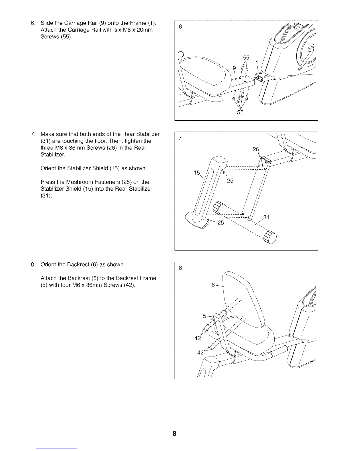
Slide the Carriage Rail (9) onto the Frame (1).
Attach the Carriage Rail with six M8 x 20mm
Screws (55).
55
55
, Make sure that both ends of the Rear Stabilizer
(31) are touching the floor. Then, tighten the
three M8 x 36mm Screws (26) in the Rear
Stabilizer.
Orient the Stabilizer Shield (15) as shown.
Press the Mushroom Fasteners (25) on the
Stabilizer Shield (15) into the Rear Stabilizer
(31).
,
Orient the Backrest (6) as shown.
Attach the Backrest (6) to the Backrest Frame
(5) with four M6 x 36mm Screws (42).
7
26
15\
31
8
 Loading...