

Proform 831215212 Owner’s Manual
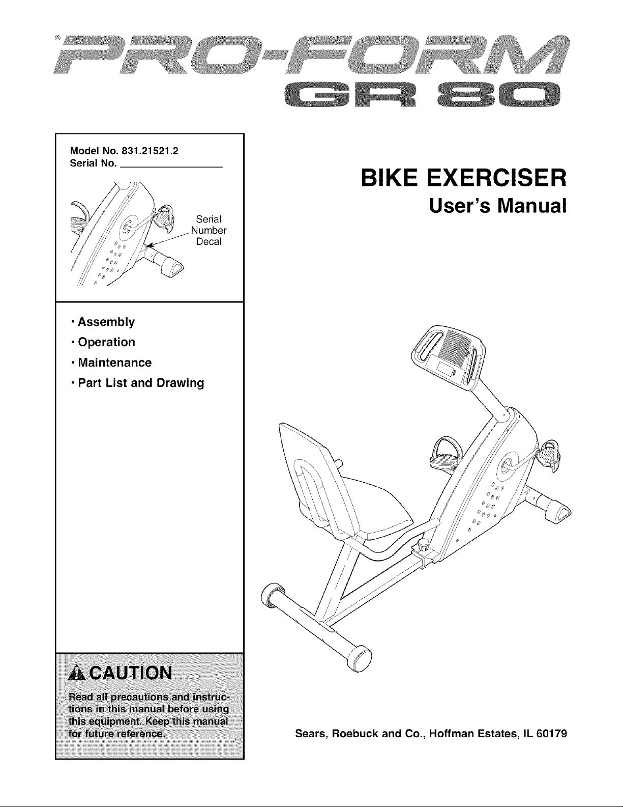
Model No. 831.21521.2
Serial No.
• Assembly
• Operation
• Maintenance
• Part List and Drawing
BIKE EXERCISER
User's Manual
Serial
Decal
Sears, Roebuck and Co., Hoffman Estates, IL 60179
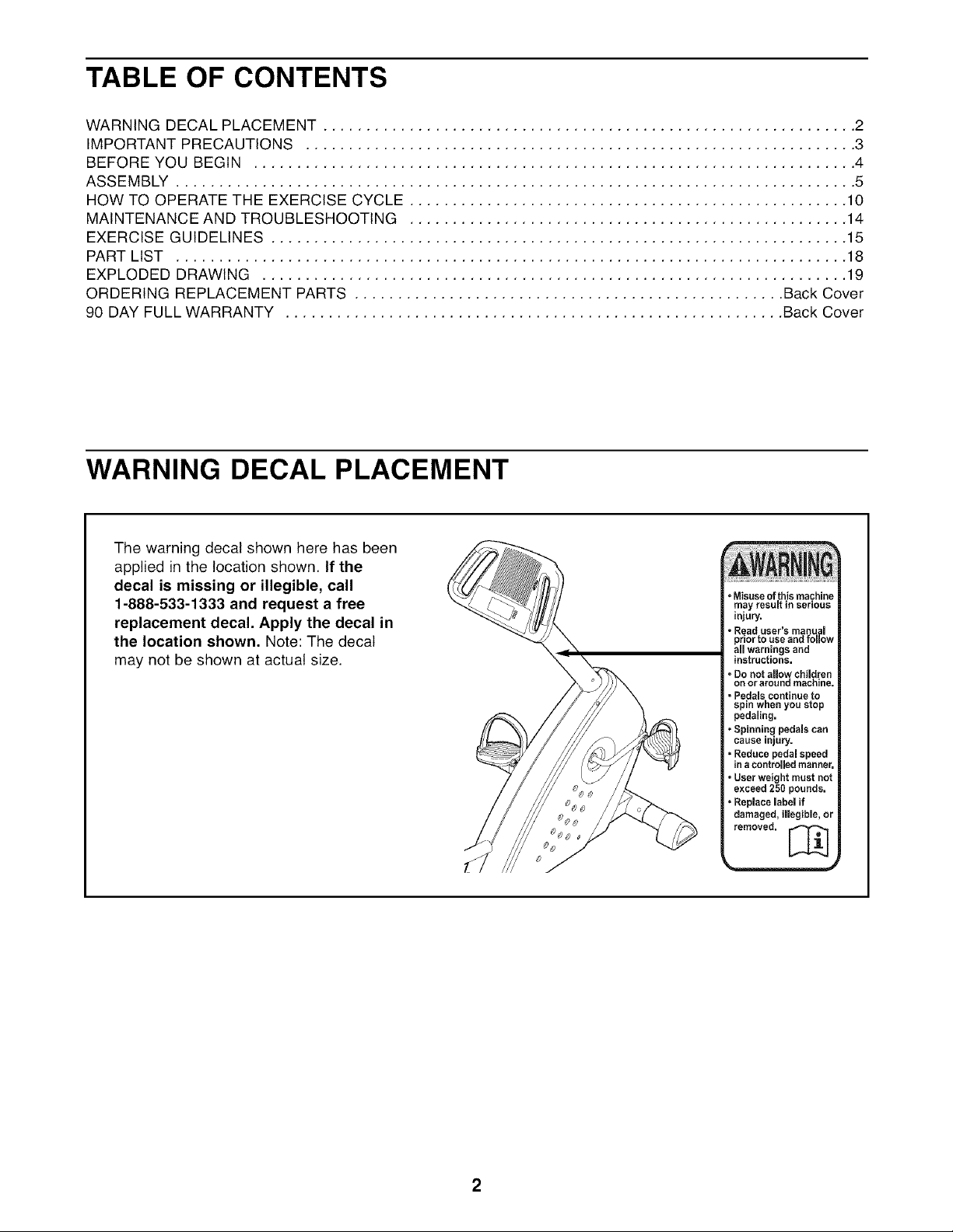
TABLE OF CONTENTS
WARNING DECAL PLACEMENT .............................................................. 2
IMPORTANT PRECAUTIONS ................................................................ 3
BEFORE YOU BEGIN ...................................................................... 4
ASSEMBLY ............................................................................... 5
HOW TO OPERATE THE EXERCISE CYCLE ................................................... 10
MAINTENANCE AND TROUBLESHOOTING ................................................... 14
EXERCISE GUIDELINES ................................................................... 15
PART LIST .............................................................................. 18
EXPLODED DRAWING .................................................................... 19
ORDERING REPLACEMENT PARTS .................................................. Back Cover
90 DAY FULL WARRANTY .......................................................... Back Cover
WARNING DECAL PLACEMENT
The warning decal shown here has been
applied in the location shown. If the
decal is missing or illegible, call
1-888-533-1333 and request a free
replacement decal. Apply the decal in
the location shown, Note: The decal
may not be shown at actual size.
• Misuseof this machine
may result in serious
injury.
° Read user's manual
prior to use and follow
all warnings and
instructions.
° Do not allow children
on or around machine,
• Pedals continue to
spin when you stop
pedaling.
• Spinning pedals can
cause Injury,
=Reduce pedal speed
in acontrolled manner.
• User weight must not
exceed 250 pounds.
• Replace label if
damaged, illegible, or
removed. [_

IMPORTANT PRECAUTIONS

BEFORE YOU BEGIN
Congratulations for selecting the new PROFORM ®GR
80 exercise cycle. Cycling is one of the most effective
exercises for increasing cardiovascular fitness, build-
ing endurance, and toning the body. The GR 80 exer-
cise cycle offers a selection of features designed to let
you enjoy this healthful exercise in the convenience
and privacy of your home.
For your benefit, read this manual carefully before
you use the exercise cycle. If you have questions
Fan
Console
after reading this manual, please see the back cover
of this manual. To help us assist you, note the product
model number and serial number before contacting
us. The model number and the location of the serial
number decal are shown on the front cover of this
manual.
Before reading further, please familiarize yourself with
the parts that are labeled in the drawing below.
Pulse Sensor
-- Pedal/Strap
Wheel
Seat
Adjustment Knob
Handlebar
4
ASSEMBLY
Assembly requires two persons. Place all parts of the exercise cycle in a cleared area and remove the
packing materials. Do not dispose of the packing materials until assembly is completed.
In addition to the included tools, assembly requires a Phillips screwdriver __ and two
adjustable wrenches G_-_,
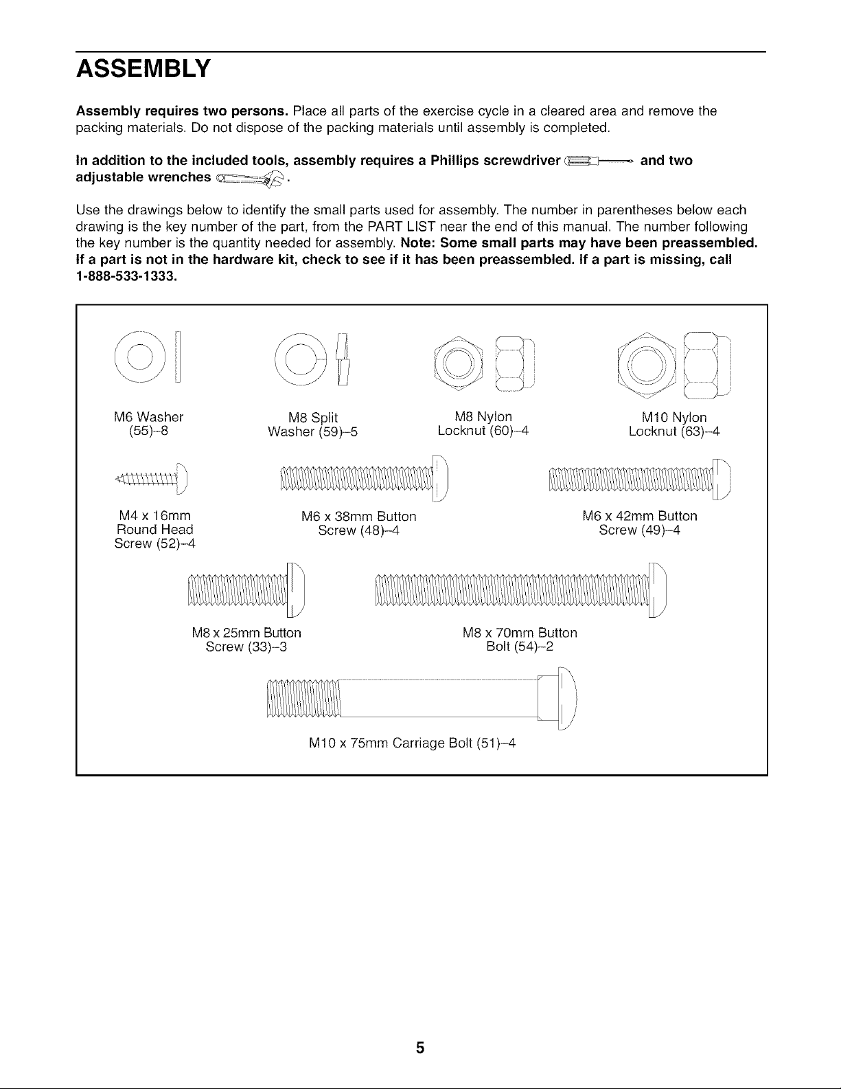
Use the drawings below to identify the small parts used for assembly. The number in parentheses below each
drawing is the key number of the part, from the PART LIST near the end of this manual. The number following
the key number is the quantity needed for assembly. Note: Some small parts may have been preassembled.
If a part is not in the hardware kit, check to see if it has been preassembled. If a part is missing, call
1-888-533-1333.
M6 Washer M8 Split M8 Nylon M10 Nylon
(55)-8 Washer (59)-5 Locknut (60)-4 Locknut (63)-4
M4 x 16mm
Round Head
Screw (52)-4
M8 x 25mm Button
Screw (33)-3
M6 x 38mm Button
Screw (48)-4
M8 x 70mm Button
M10 x 75mm Carriage Bolt (51)-4
M6 x 42mm Button
Screw (49)-4
Bolt (54)-2
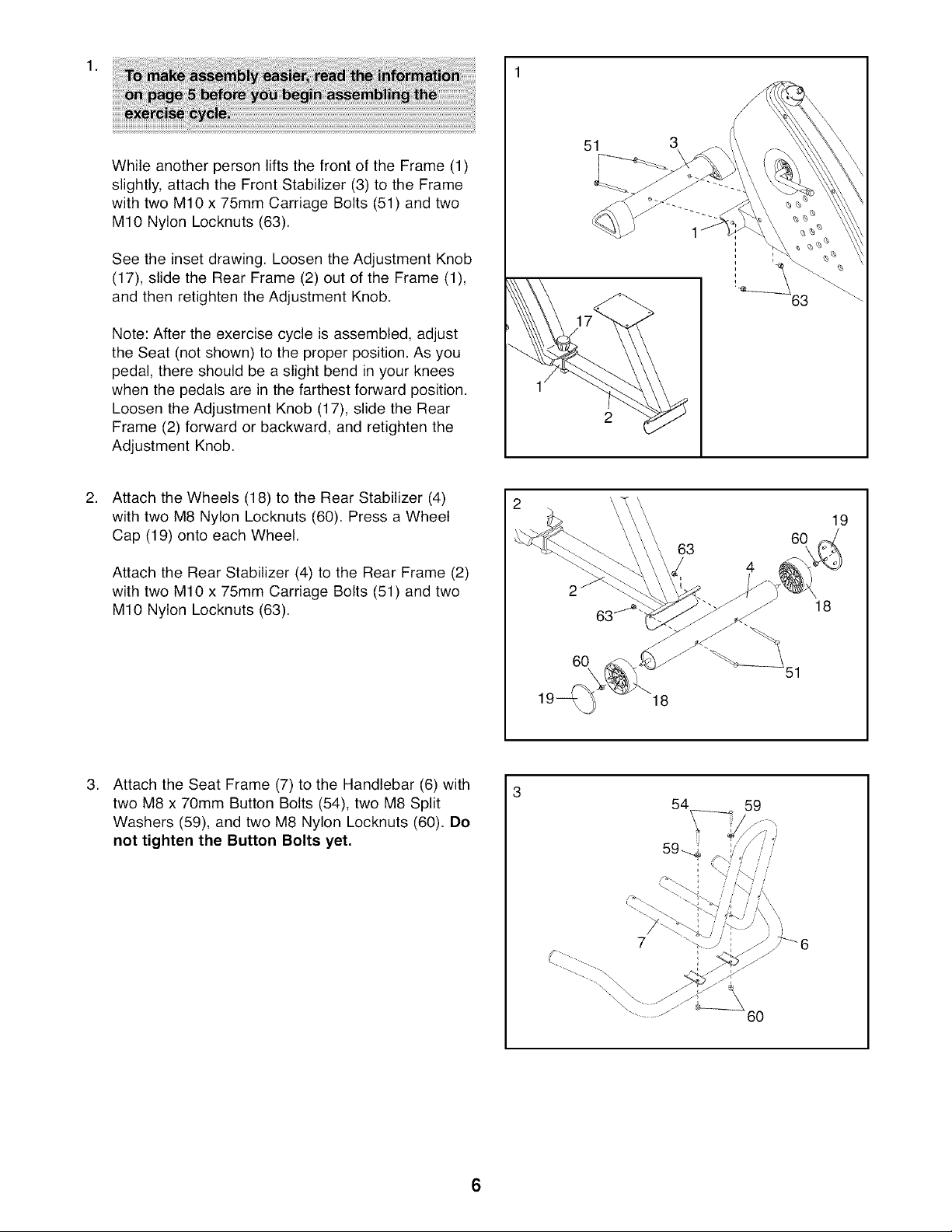
WhileanotherpersonliftsthefrontoftheFrame(1)
slightly,attachtheFrontStabilizer(3)totheFrame
withtwoM10x75mmCarriageBolts(51)andtwo
M10NylonLocknuts(63).
Seetheinsetdrawing.LoosentheAdjustmentKnob
(17),slidetheRearFrame(2)outoftheFrame(1),
andthenretightentheAdjustmentKnob.
Note:Aftertheexercisecycleisassembled,adjust
theSeat(notshown)totheproperposition.Asyou
pedal,thereshouldbea slightbendinyourknees
whenthepedalsareinthefarthestforwardposition.
LoosentheAdjustmentKnob(17),slidetheRear
Frame(2)forwardorbackward,andretightenthe
AdjustmentKnob.
AttachtheWheels(18)totheRearStabilizer(4)
withtwoM8NylonLocknuts(60).PressaWheel
Cap(19)ontoeachWheel.
AttachtheRearStabilizer(4)totheRearFrame(2)
withtwoM10x 75mmCarriageBolts(51)andtwo
M10NylonLocknuts(63).
51
63
19
60
18
.
Attach the Seat Frame (7) to the Handlebar (6) with
two M8 x 70mm Button Bolts (54), two M8 Split
Washers (59), and two M8 Nylon Locknuts (60). Do
not tighten the Button Bolts yet,
60
18
54
59
60
6
 Loading...