

Page 1
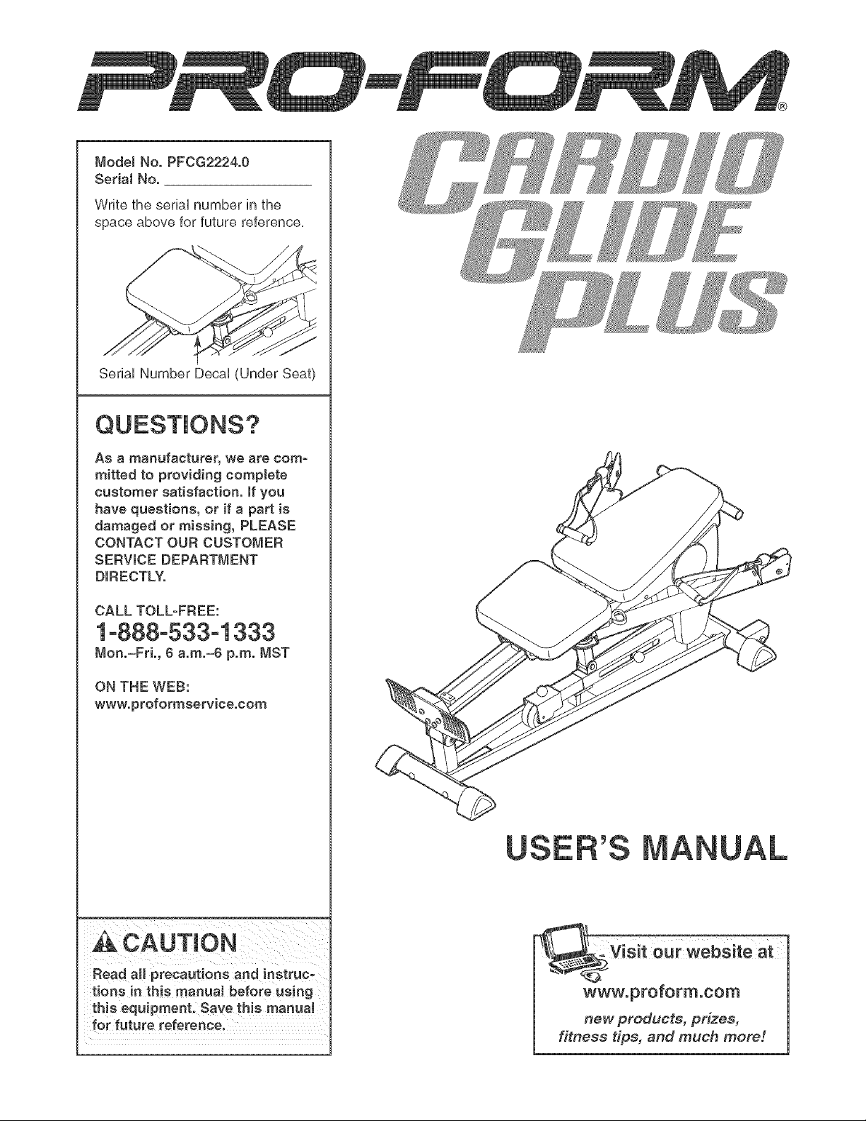
ModelNo.PFCG2224.0
SerialNo.
WritetheseriaUnumberinthe
spaceaboveforfuturereference.
SeriaUNumberDecaU(UnderSeat)
Asamanufacturer,wearecom-
mittedto providingcomplete
customersatisfaction,if you
have questions, or if a part is
damaged or missing, PLEASE
CONTACT OUR CUSTOMER
SERVICE DEPARTMENT
DIRECTLY.
CALL TOLL-FREE:
1o888o533o1333
Mon.=Fri., ¢ a.m.=6 p.m. MST
ON THE WEB:
www.proformservice.com
Read aH precautions and instruc-
tions in this manua_ before using
this equipment. Save this manual
for future reference.
our ,ebs teat--
www.proform.com
new products, prizes,
fitness tips, and much meter.
Page 2
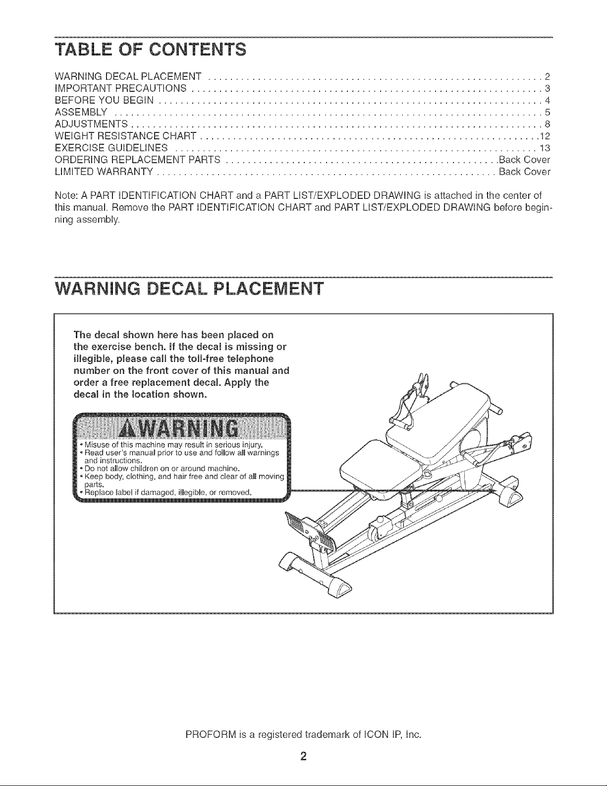
TABLE OF CONTENTS
WARNING DECAL PLACEMENT ............................................................. 2
iMPORTANT PRECAUTIONS ................................................................ 3
BEFORE YOU BEGIN ...................................................................... 4
ASSEMBLY .............................................................................. 5
ADJUSTMENTS ........................................................................... 8
WEIGHT RESISTANCE CHART .............................................................. 12
EXERCISE GUiDELiNES .................................................................. 13
ORDERING REPLACEMENT PARTS .................................................. Back Cover
LiMiTED WARRANTY .............................................................. Back Cover
Note: A PART iDENTiFiCATiON CHART and a PART LIST/EXPLODED DRAWING is attached in the center of
this manual, Remove the PART iDENTiFiCATiON CHART and PART LIST/EXPLODED DRAWING before begin-
ning assembly,
WARNING DECAL PLACEMENT
The decal shown here has been placed on
the exercise bench. If the decaJ is missing or
illegibJe, please call the toll-free telephone
number on the front cover of this manuaJ and
order a free replacement decal Apply the
decal in the tocation shown.
Misuse of this machine may result in serious injury.
Read user's manuaB prior to use and follow aHwarnings
and instructions.
Do not allow children on or around machine.
Keep body, clothing, and hair free and clear of aH moving
parts.
_ble, o_emoved.
PROFORM is a registered trademark of ICON IP, Inc,
2
Page 3
iMPORTANT PRECAUTIONS
AWARNING: Toreducethedekofeedous_njury,readthefo,ow_ng_mportantpreeaut_ons
before using the exercise bench.
Read all instructions in this manual and all 7. Keep hands and feet away from moving parts.
warnings on the exercise bench before using
the exercise bench. Use the exercise bench 8. Always wear atHetic shoes for foot protec-
only as described in this manual, tion while exercising.
2.
It is the responsibility of the owner to ensure 9.
that all users of the exercise bench are ade-
quateJy informed of aH precautions.
3. The exereiee bench is intended for home use
only. Do not use the exercise bench in any
commercial, rental, or institutional setting.
Keep the exercise bench indoors, away from
moisture and duet. Place the exercise bench
an a level surface, with a mat beneath it to
protect the fJoor or carpet. Make sure that
there is enough clearance around the exer=
cise bench to mount and dismount the exer-
cise bench and to perform the intended exer- exercising, stop immediately and make sure
cises° that the rope is on the puHeyso Replace the
=
Make sure aH parts are properly tightened
each time the e_erciee bench is used°
Replace any worn parts immediately.
=
Keep children under 12 and pets away from
the exercise bench at aJl times.
The exercise bench is designed to support a
maximum user weight of 250 pounds.
10. The exercise bench is designed to use the
user's weight as the resistance. Do not use
the exercise bench with dumbbells or any
other type of weight to increase the resist-
ance°
11. Always make sure the backrest frame is fully
engaged before using the backrest.
12. Make sure that the rope remains on the pul°
leye at aH times, if the rope binds as you are
rope at least every two years.
13. if you feel pain or dizziness at any time while
exercising, stop immediateJy and begin cool=
ing down.
"_ WAR NING: Beforebeginniogtheeoranyexerciseprogram,consultyourp.yeieJan.Thee
is especially important for persons over the age of 35 or pereone with pre-existing health problemso
Fiead aH instructions before using, iCON assumes no responsibility for personal injury or property
damage sustained by or through the use of this product.
3
Page 4

BEFORE YOU BEGIN
Thank you for selecting the versatile PROFORM _ CAR°
DIO GLIDE PLUS exercise bench, The exercise bench
is designed to develop every major muscie group of the
body, Whether your goal is to tone your body, build dra-
matic muscle size and strength, or improve your cardio°
vascular system, the exercise bench wHi heip you to
achieve the specific resuits you want,
For your benefit, read this manuaJ carefully before
using the exercise bench, if you have questions after
reading this manual see the front cover of this manu-
aL To heip us assist you, piease note the product
modei number and seriaHnumber before caiHng, The
Handle
Backrest
Seat
Rail
model number isPFCG2224,0, The serialnumber can
be foundon a detailattachedto theexercisebench
(seethefrontcoverofthismanual forthe locationof
the decai),
To avoid a registration fee for any service needed
under warranty, you must register the exercise
bench at www.proformservice.com/registration.
Before reading further, please review the drawing
below and familiarize yourself with the parts that are
labeled,
Arm
Console
Foot Rest
Base
Resistance Knob
Resistance Leg
ASSEMBLED DiMENSiONS:
Height: 25 in, / 64cm
Width: 63 in, / 160cm
Depth: 56 in, / 142cm
Weight: 105 Ibs,/ 48 kg
4
Page 5
Make Things Easier for Yourself
Everything in this manual is designed to ensure
that the weight bench can be assemoled suc-
cessfully by anyone. Most people find that by
setting aside plenty of time, assembly will go
smoothly,
To hire an authorized service technician to
assemble the exercise bench, call toll-free
1-800-445-2480.
Before beginning assembJy, carefully read the
following information and instructions:
• As you assemble the weight bench, make sure all
parts are oriented as shown in the drawings,
, For help identifyinq srnaH parts, use the PART
HDENTHFHCATHONCHART.
The included hex key(s} -@ , and the
following tools (not included) may be required
for assembly:
• Two adjustable wrenches
• One rubber mallet
• One standard screwdriver L-__}
• Assembly requires two people,
• Tighten all parts as you assemble them, unless
instructed to do otherwise,
• Place all parts in a cleared area and remove the
packing materials, Do not dispose of the packing
materials until assembly is completed,
Before beginningassembly,makesureyou
understand the information in the box
above. For heJp identifying small parts, use
the PART mDENTmFmCATmONCHART in the
center of this manual
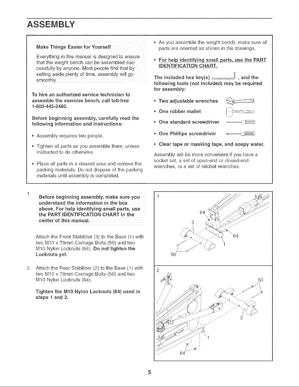
Attach the Front Stabilizer (3) to the Base (1) with
two MIO x 78mm Carriage Bolts (50) and two
MIO Nylon Locknuts (64), Do not tighten the
Locknuts yet.
Attach the Rear Stabilizer (2) to the Base (1) with
two MIO x 78ram Carriage Bolts (50) and two
MIO Nylon Locknuts (64),
• One Philtips screwdriver _====_LX_
• Clear tape or masking tape, and soapy water.
Assembly wiii be more convenient if you have a
socket set, a set of open-end or closed-end
wrenches, or a set of ratchet wrenches,
64
5O
5O
Tighten the M!O Nyton Locknuts (64) used in
steps 1 and 2.
Page 6
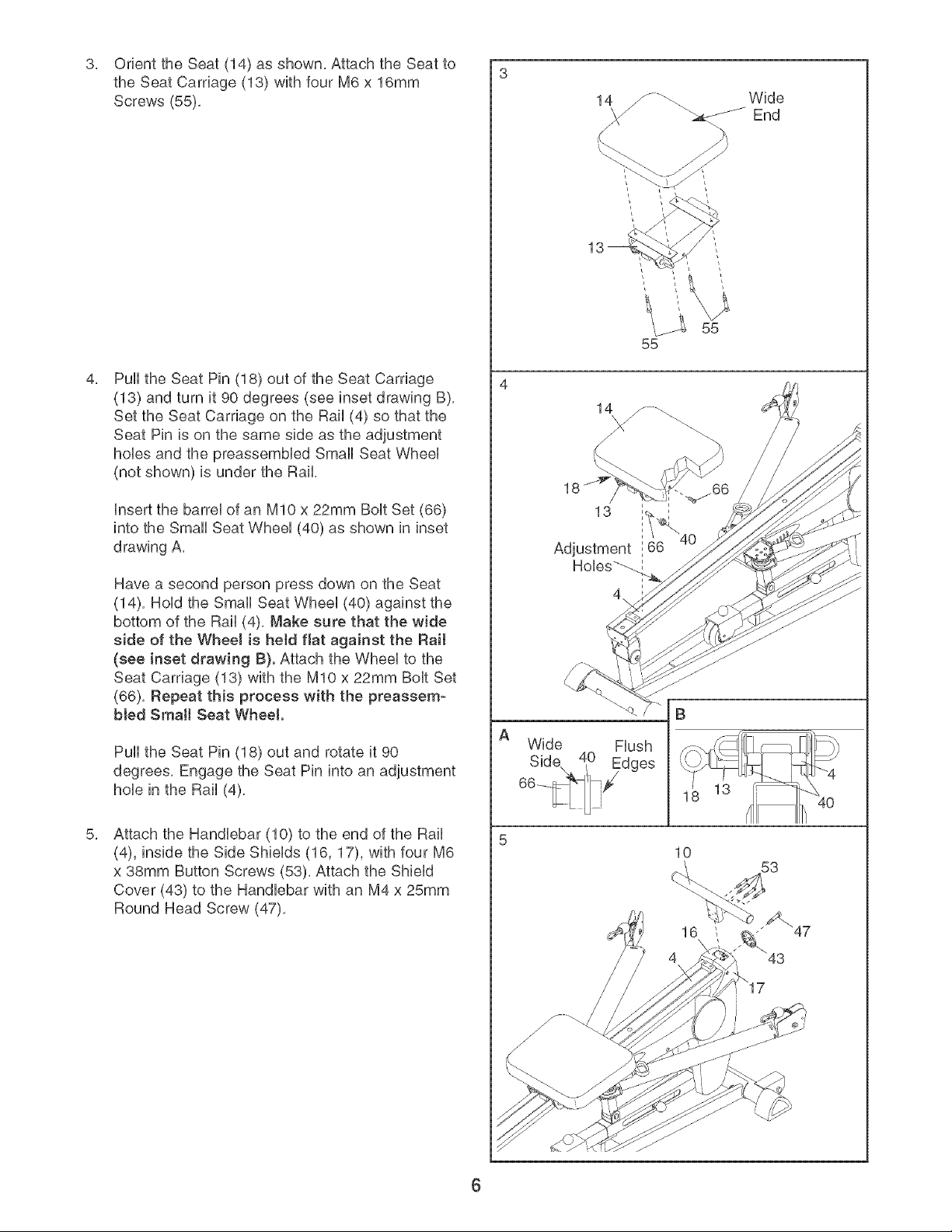
OrienttheSeat(14)asshown,AttachtheSeatto
3, 3
theSeatCarriage(13)withfourM6x16mm
Screws(55),
PulltheSeatPin(18)outof theSeatCarriage
(13)andturnit90degrees(seeinsetdrawingB),
SettheSeatCarriageontheRail(4)sothatthe
SeatPinisonthesamesideastheadjustment
hoUesandthepreassemMedSmallSeatWheeU
(notshown)isundertheRail,
UnsertthebarreUofanMIOx22mmBoUtSet(66)
intotheSmallSeatWheeU(40)asshownininset
drawingA,
Wide
&_J-_-_End
55
HaveasecondpersonpressdownontheSeat
(14),HoUdtheSmallSeatWheeU(40)againstthe
bottomoftheRail(4),Makesurethatthewide
sideoftheWheeJis heldflatagainsttheRail
(seeinsetdrawingB).AttachtheWheeUtothe
SeatCarriage(13)withtheMIOx22mmBoUtSet
(66),Repeatthisprocesswiththe preassem-
bledSrnaHSeatWheel
PulltheSeatPin(18)outandrotateit90
degrees,EngagetheSeatPinintoanadjustment
holeintheRail(4),
AttachtheHandlebar(10)totheendoftheRail
(4),insidetheSideShields(16,17),withfourM6
x38mmButtonScrews(53),AttachtheShield
Cover(43)to theHandlebarwithanM4x25mm
RoundHeadScrew(47),
Wide
Flush
13 I IIh 40
6
Page 7

Orient the Backrest (12) so that the narrow end is
over the top of the Backrest Frame (11). Attach
the Backrest to the Backrest Frame with two M6 x
25mm Screws (77) and two M6 x 45mm Screws
(78).
Slide the top of the Backrest Frame (11) under
the Handlebar (10). Pivot the Backrest Frame
down onto the Rail (4) so that the pin on the
Backrest Frame is inserted into the hole in the
Rail.
Narrow
End
77
78
10
11
8. Attach the Foot Hate (9) to the Rail (4) with four
M6 x 25mm Button Screws (57). Do not tighten
the Screws yet.
Connect the Wire (63) to the ConsoHe(84). The
connector should slide easily into the socket
and snap into place. Hfit does not, turn the con-
nector over and then insert it. IF THE CONNEC-
TOR IS NOT INSERTED PROPERLY, THE CON-
SOLE MAY BE DAMAGED WHEN THE POWER
IS TURNED ON. Push the excess Wire into the
Rail (4).
insert three "AA" batteries (not included) into the
Console (84). Alkaline batteries are recommended.
Hole
57
57
Attach the Console (84) to the Rail (4) and the
Foot Hate (9) with four M4 x 16mm Screws (76).
Tighten the four M6 × 25rnrn Screws (57} used
in step 8.
10. Make sure that aHHparts have been properHy tight-
ened. The use of the remaining parts wHHbe
expHained in ADJUSTMENTS, beginning on the
foHHowingpage.
76
7
Page 8

ADJUSTMENTS
This section expUains how to adjust the exercise bench. See the EXERCISE GUUDEMNES on page 13 for impor-
tant information about how to get the most benefit from your exercise program, Refer to the accompanying exer-
cise guide to see the correct form for each exercise,
Make sure all parts are properly tightened each time the exercise bench is used, Replace any worn parts imme-
diately, The exercise bench can be cleaned with a damp cloth and a mild, non-abrasive detergent, Do not use
solvents,
ATTACHING THE BACKREST
Slide the top of the Backrest Frame (11) under the
Handlebar (10), Pivot the Backrest Frame down onto
the Rail (4) so that the pin on the Backrest Frame is
inserted into the hob in the Rail
the pin on the Backrest Frame (11) is inserted
into the hole before using the Backrest (12).
/
/
10
ADJUSTING THE SEAT
To adjust the Seat (14) to a different position on the
Rail (4), pull the Seat Pin (18) out as far as it will go,
Move the Seat to the new position and engage the
Seat Pin into the Rail,
To allow the Seat (14) to roil on the Rail (4), pull the
Seat Pin (18) out and turn it 90 degrees, Engage the
Seat Pin into the Seat Carriage (18),
the Seat Pin (18) !s fully engaged bef0re us!ng
the exercise bench.
18
\
4
\
\
8
Page 9

ATTACHING THE ACCESSORmES
A Handb (68) can be attached to the Rope (80) with
a CHp (83), The other accessories can be attached
to the Rope in the same manne_.
ADJUSTING THE RESISTANCE SETTING
To adjust the resistance setting, pull the Resistance
Knob (27) and use the Knob (71) to slide the
Resistance Leg Extension (7) into or out of the
Resistance Leg (8), Engage the Resistance Knob into
the Resistance Leg.
/
/
the Resistance Knob (27) is fully engaged into
the Resistance Leg (8) before Using the exercise
bench.
ADJUSTING THE ARM POSITION
Change the position of an Arm (5 or 6) by pulling the
Arm Pin (21) until it disengages the bracket on the
Rail (4), Pivot the Arm to the new position and re°
engage the Arm Pin into the Rail bracket.
the Arm Pin (21) is fully engaged into the bracket
on the Rail (4) before using the exercise bench.
/
/
8
27
7
71
4
/
Bracket
21
Page 10

REPLACmNGTHEBATTERmES
RemovethefourM4x 16mmScrews(76)fromthe
ConsoUe(84),Insertthree"AA"batteriesinthe
ConsoUebatterycase,AUkaHnebatteriesarerecom-
mended,ReattachtheConsoUeto theRail(4)andthe
FootHate(9)withthefourScrews,
TIGHTENINGTHEROPE
ThetypeofRope(80)usedontheexercisebench
canstretchslightlywhenitisfirstused,ffthereis
sUackintheRopebeforeresistanceisfeUt,theRope
shouUdbetightened,
Battery
Case
76
76
15
84
\
TotightentheRope(80),firstpulloneendoftheRope
outuntiltheRopeistight,Then,measurethedistance
betweentheRopeCover(79)andtheSwiveUArm(15),
HaveasecondpersonpulltheRope(80)outand
holditwNetheRopeisadjusted.PushtheRope
Cover(79)downtheRopeandUoosenthetwoM5x
21mmFUatHeadScrews(72),PulltheRopethrough
theCHp(83)andtheCUamps(81,82)toshortenthe
Ropebythemeasuredamount,Makesurethat
thereis 1/4"betweentheClampsandtheCJip.
Then,retightenthetwoScrewsandcovertheClamps
withtheRopeCover.
two M5x 21ram Fiat Head Screws (72) are fully
tightened before the exercise bench is used.
Measure
Distance
8O
72
79
I
\\
81
82
10
Page 11

FEATURES OF THE CONSOLE
1. Turn on the power.
The consob features five modes that provide instant
exercise feedback during your workouts, The modes
are described below,
Cycles/Minute--This mode displays the number of
repetitions you are completing per minute,
Time--This mode displays the elapsed time, Note: if
you stop exercising for a few seconds, the time mode
wiii pause,
Total Cycles--This mode displays the total number of
repetitions you have completed during your workout,
Calories--This mode displays the approximate num-
ber of calories you have burned,
Scan--This mode displays the Cycles/Minute, Time,
Total Cycles, and Calories modes, for a few seconds
each, in a repeating sequence,
HOW TO OPERATE THE CONSOLE
Make sure that there are batteries in the console (see
BATTERY REPLACEMENT on page 10), if there is a
sheet of clear plastic on the face of the console,
remove the plastic,
Follow the steps at the right to operate the console,
To turn on the power, press the On/Reset button or
begin exercising, The entire display will light for a
moment; the console will then be ready for use,
2. Select the desired mode.
Scan mode--
When the power
is turned on, the
Scan mode will be
selected, One
mode indicator will
appear below the
word "SCAN," and
a second mode
indicator will show
which mode is
currently dis-
played, Note: if you have selected a different
mode, you can reselect the Scan mode by pressing
the Mode button repeatedly,
CycJes/Minute,
Time, TotaJ
Cycles, or
CaJodes mode--
To select a single
mode for continu-
ous display, press
the Mode button
repeatedly, The
mode indicators
wiii show which mode is selected, Make sure there
is not a mode indicator below the word "SCAN,"
To reset the console at any time, press the
On/Reset button,
3. Turn off the power.
To turn off the power, simply wait for a few minutes,
The console has an "auto-off" feature, if the con-
sob buttons are not pressed and the rope is not
pulled for a few minutes, the console will turn off to
conserve the batteries,
Mode indicators
CYCLES/MIN. TIME TOTAL CYCLES
: SCAN CALORIES
I sl_.
CYCLES/MIN _ TOTALCYCLES
11
Page 12

WEIGHT RESISTANCE CHART
The exercise bench uses a percentage of the user's weight as resistance for exercising, The charts beUowshow
the approximate resistance in pounds for six popuUar exercises, Note: The actual resistance for each exercise
may vary due to differences in friction levels between the cables, pulleys, and other moving parts.
Biceps Cud, Chest Fly, Chest Press
m 1 2 3 4 5 6
t00
110
t20
130
_ 140
150
170
i80
190
210
220
230
24O
Leg Press, Overhead Extension, Shoulder Press
26
27
27
28
29
3O
31
32
33
34
35
36
37
39
39
4O
31 37 44 51 59
32 38 46 53 61
33 40 47 55 64
34 41 49 57 67
35 43 51 60 70
36 45 54 63 73
38 47 56 66 76
40 49 59 69 80
41 51 61 72 83
43 53 64 75 87
45 55 67 79 92
46 58 70 83 96
48 60 74 87 101
50 63 77 91 106
52 65 80 94 110
53 68 83 98 115
7 8
67 76 85 94 103
70 79 88 98 107
73 82 92 102 111
76 86 96 106 116
79 90 100 111 121
83 94 105 116 127
87 98 110 121 133
91 103 115 127 139
95 108 120 133 145
100 113 126 139 152
104 118 132 146 160
110 124 138 153 167
115 130 145 160 175
120 136 152 168 184
125 142 158 175 191
131 148 165 183 200
9 t0
1!
130
150
P 170
laO
t_
200
210
220
230
240
250
26
27
27
28
29
3O
31
32
33
34
35
36
37
38
39
4O
30 35 40 47 55
31 36 42 49 57
32 38 43 51 60
33 39 45 53 63
34 41 47 56 66
36 43 50 59 69
37 45 52 62 72
39 47 55 65 76
40 49 57 68 79
42 51 60 71 83
44 53 63 75 88
45 56 66 79 92
47 58 70 83 97
49 61 72 86 101
51 63 74 89 104
52 66 76 91 108
12
63 71 79 88 98
66 74 82 92 102
69 77 86 96 106
72 81 90 100 111
75 85 94 105 116
79 89 99 110 122
83 93 104 115 128
87 98 109 121 134
91 103 114 127 140
96 108 120 133 147
100 113 126 140 155
106 119 132 147 162
111 125 139 154 170
116 131 145 161 178
120 135 151 167 185
124 140 157 174 192
Page 13

EXERCISE GUiDELiNES
THE FOUR BASmCTYPES OF WORKOUTS
Muscle Building--To increase muscie size, use a high
amount of resistance, Your muscies wHiadapt and grow
as you progressiveiy increase the intensity of your exer-
cise by:
changing the ievei of resistance
changing the number of repetitions or sets performed,
(A "repetition" is one compiete cycHeof an exercise,
such as one sit-up, A "set" is a series of repetitions,)
The proper amount of resistance for each exercise
depends upon the individual You must gauge your Him-
its and select the amount of resistance that is right for
you, Begin with 3 sets of 8 repetitions for each exercise
you perform, When you can compHete3 sets of 12 rep-
etitions without difficuity, increase the amount of resist-
ance, Rest for 3 minutes after each set,
Toning--Tone your muscles by using a moderate
amount of resistance and increasing the number of rep-
etitions in each set, Compiete as many sets of 15-20
repetitions as possibie without discomfort, Rest for 1
minute after each set,
Warming Up--Begin each workout with 5-10 minutes
of stretching and light exercise to warm up, Warming up
prepares your body for more strenuous exercise by rais-
ing your body temperature, increasing circulation, and
delivering more oxygen to your muscles,
Working Out--Each workout should include 6-10 dif-
ferent exercises, Select exercises for every major mus-
cle group, emphasizing areas that you want to develop
most, To give balance and variety to your workouts,
vary the exercises from session to session,
Schedule your workouts for the time of day when your
energy level is the highest, Each workout should be fop
lowed by at bast one day of rest, Once you find the
right schedule for you, stick with it,
Exercise Form--Maintaining proper form is an essen-
tial part of an effective exercise program, This requires
moving through the full range of motion for each exer-
cise, and moving only the appropriate parts of the body,
Exercising in an uncontrolled manner will leave you feel-
ing exhausted, The exercise guide show the correct
form for several exercises and describes how to per-
form the exercise,
Weight Loss--To lose weight, use a low amount of
resistance and increase the number of repetitions in
each set, Exercise for 20-30 minutes, resting for a max-
imum of 30 seconds between sets,
Cross Training--Cross training is an efficient way to
get a compiete and weli-balanced fitness program, An
exampie of a balanced program is:
Strength training workouts on Monday, Wednesday,
and Friday,
20-30 minutes of aerobic exercise, such as riding an
exercise bike or running on a treadmili, on Tuesday
and Thursday,
Rest from both strength training and aerobic exercise
for at bast one fuli day each week to give your body
time to regenerate,
PERSONALIZING YOUR EXERCISE PROGRAM
Determining the right length of time for each workout, as
well as the number of repetitions and sets completed, is
an individual matter, it is important to avoid overdoing it
during the first few months of your exercise program,
You should progress at your own pace and be sensitive
to your body's signals, if you experience pain or dizzi-
ness at any time while exercising, stop immediately and
begin cooling down, Find out what is wrong before con-
tinuing, Remember that adequate rest and a proper diet
are important factors in any exercise program,
The repetitions in each set should be performed
smoothly and without pausing, A repetition's exertion
stage should last about half as long as the return stroke,
Proper breathing is important, Exhale during the exer-
tion stage of each repetition and inhale during the return
stroke, Never hold your breath, Rest for a short period
of time after each set, The time depends on which type
of workout you are performing (see THE FOUR BASIC
TYPES OF WORKOUTS),
Plan to spend the first couple of weeks familiarizing
yourself with the equipment and learning the proper
form for each exercise,
Cooting Down--End each workout with 5-10 minutes
of stretching, Include stretches for both your arms and
legs, Move slowly as you stretch and do not bounce,
Ease into each stretch gradually and go only as far as
you can without strain, Stretching at the end of each
workout is an effective way to increase flexibility,
Staying Motivated--For motivation, keep a record of
each workout, The charts on pages 14 and 15 can be
photocopied and used to record your workouts, List
the date, the exercises performed, the resistance used,
and the numbers of sets and repetitions completed,
Record your weight and key body measurements at the
end of every month, Remember, the key to achieving
the greatest results is to make exercise a regular and
enjoyable part of your everyday life,
13
Page 14

MONDAY EXERCISE WEIGHT SETS REPS
Date:
/ /
TUESDAY
Date:
/ /
Date:
/ /
Date:
/
AEROBIC EXERCISE
EXERCISE WEIGHT SETS REPS
AEROBIC EXERCISE
FRIDAY EXERCISE WEIGHT SETS REPS
Date:
/ /
Make photocopies of this page for scheduling and recording your workouts,
14
Page 15

MONDAY EXERCISE WEIGHT SETS REPS
Date:
/ /
TUESDAY
Date:
/ /
Date:
/ /
Date:
/
AEROBIC EXERCISE
EXERCISE WEIGHT SETS REPS
AEROBIC EXERCISE
FRIDAY EXERCISE WEIGHT SETS REPS
Date:
/ /
Make photocopies of this page for scheduling and recording your workouts,
15
Page 16

PART iDENTiFiCATiON CHART
Refer to the drawings below to identify small parts used in assembly, The number in parentheses by each draw-
ing is the key number of the part, from the PART LiST in the center of this manual, Note: Some small parts
may have been pre-attached, if a part is not in the parts bag, check to see if it has been pre-attached.
MIO x 78mm Carriage Bolt (50)
, 1}
M6 x 45mm Screw (78)
M6 x 38mm Button Screw (53)
D
M6 x 25mm Button Screw (57)
M6 x 25ram Screw (77)
MIO Nylon Locknut (64)
M4 x 25mm Round Read Screw (47)
MIO x 22mm Bolt Bet (66)
M6 x 16ram Screw (55)
M4 x 16ram Screw (76)
Page 17

PART LlST Model No. PFCG 24.0 R0208C
Key No. Qty. Description Key No. Qty.
1 1 Base 46 4
2 1 Rear Stabilizer 47 5
3 1 Front Stabilizer 48 1
4 1 Rail 49 4
5 1 Left Arm 50 4
6 1 51 2
7 1 Resistance Leg Extension 52 1
8 1 Resistance Leg 53 4
9 1 Foot Hate 54 2
10 1 HandUebar 55 4
11 1 Backrest Frame 56 1
12 1 Backrest 57 4
13 1 Seat Carriage 58 2
14 1 Seat 59 2
15 2 SwiveUArm 60 1
16 1 Right Side ShieUd 61 1
17 1 Left Side ShieUd 62 1
18 1 Seat Pin 63 1
19 4 Stabilizer Endcap 64 6
20 2 WheeU 65 1
21 2 Arm Pin 66 2
22 2 Hastic Spacer 67 1
23 2 Small Hastic Spacer 68 2
24 4 Arm Bushing 69 2
25 1 AnMe Strap 70 5
26 2 Stabilizer Wheel 71 1
27 1 Resistance Knob 72 6
28 1 Bumper 73 2
29 2 Stop Pad 74 2
30 2 Rail Cover 75 6
31 2 Arm SUeeve 76 8
32 2 1 3/4" Pulley 77 2
33 9 2" Pulley 78 2
34 2 Base Bushing 79 2
35 2 Rail Bushing 80 1
36 1 Reed Switch 81 2
37 2 2 1/8" Pulley 82 2
38 4 Swivel Arm Bushing 83 2
39 2 Lower Rail Bushing 84 1
40 2 Small Seat Wheel 85 1
41 4 Seat Wheel 86 2
42 2 Handlebar Endcap 87 2
43 1 Shield Cover # 1
44 1 Axle # 1
45 9 MIO Washer
Description
M4 x 38mm Round Head Screw
M4 x 25mm Round Head Screw
M8 x 46mm Button Screw
M6 x 8mm Bolt
MIO x 78mm Carriage Bolt
MIO x 60mm Button Bolt
M8 x 63mm Bolt Set
M6 x 38mm Button Screw
3/8" x 63mm Button Bolt
M6 x 16mm Screw
3/8"x 150mm Bolt
M6 x 25mm Button Screw
M8 x 22mm Button Bolt
3/8" x 48mm Button Bolt
3/8" x 120mm Bolt
M13 x 60mm Bolt Set
Hip Strap
Wire
MIO Nylon Locknut
MIO x 16mm Button Bolt
MIO x 22mm Bolt Set
1/2" Nylon Locknut
Handle
Snap Ring
M8 Washer
Knob
M5 x 21mm Flat Head Screw
Arm Endcap
4mm Spacer
3/8" Nylon Locknut
M4 x 16mm Screw
M6 x 25mm Screw
M6 x 45mm Screw
Rope Cover
Rope
Upper Clamp
Lower Clamp
Clip
Console
Magnet
M8 Large Washer
6mm Spacer
User's Manual
Exercise Guide
Note: "#" indicates a non-illustrated part, Specifications are subject to change
of this manual for information about ordering replacement parts,
without notice, See the back cover
Page 18

EXPLODED DRAWING--Model No. PFCG 24.0 Ro2o5c
72 32 12 _/
72
79
84
58 30 29_
i
57
25
33
20 87
21
71
82
83
72
73 .......
/
33
33
/ 33
/
33
/
68
19
!
3
/34
35
/
64 "'@
19
36
50
Page 19

ORDERmNG REPLACEMENT PARTS
To order repUacement parts, see the front cover of this manual To heUpus assist you, phase be prepared to give
the following information:
1, The MODEL NUMBER of the product (PFCG2224,0)
2, The NAME of the product (PROFORM CARDUO GMDE PLUS exercise bench)
3, The SERIAL NUMBER of the product (see the front cover of this manuaU)
4, The KEY NUMBER and DESCRiPTiON of the part(s) (see the PART LUSTand EXPLODED DRAWING at the
center of this manuaU)
LIMITED WARRANTY
iCON HeaUth & Fitness, Unc,dCON), warrants this product to be free from defects in workmanship and mate°
riaU,under normaU use and service conditions, for a period of ninety (90) days from the date of purchase, This
warranty extends onUyto the originaU purchaser, iCON's obligation under this warranty is Hmited to repUacing
or repairing, at ICON's option, the product through one of its authorized service centers, All repairs for which
warranty claims are made must be pre-authorized by ICON, If the product is shipped to a service center,
freight charges to and from the service center will be the customer's responsibility, For in-home service, the
customer will be responsible for a minimal trip charge, This warranty does not extend to any product or dam-
age to a product caused by or attributable to freight damage, abuse, misuse, improper or abnormal usage or
repairs not provided by an ICON authorized service center; products used for commercial or rental purposes;
or products used as store display models, No other warranty beyond that specifically set forth above is author°
ized by ICON,
ICON is not responsible or liable for indirect, special or consequential damages arising out of or in connection
with the use or performance of the product or damages with respect to any economic loss, loss of property,
loss of revenues or profits, loss of enjoyment or use, costs of removal or installation or other consequential
damages of whatsoever nature, Some states do not allow the exclusion or limitation of incidental or conse°
quential damages, Accordingly, the above limitation may not apply to you,
The warranty extended hereunder is in lieu of any and all other warranties and any implied warranties of mer-
chantability or fitness for a particular purpose is limited in its scope and duration to the terms set forth herein,
Some states do not allow limitations on how long an implied warranty lasts, Accordingly, the above limitation
may not apply to you,
This warranty gives you specific legal rights, You may also have other rights which vaq/from state to state,
ICON HEALTH & FITNESS, INC., 1500 S. 1000 W., LOGAN, UT 84321-9813
Part No, 220744 R0205C Printed in China @2005 iCON IP, Inc,
 Loading...