

Page 1
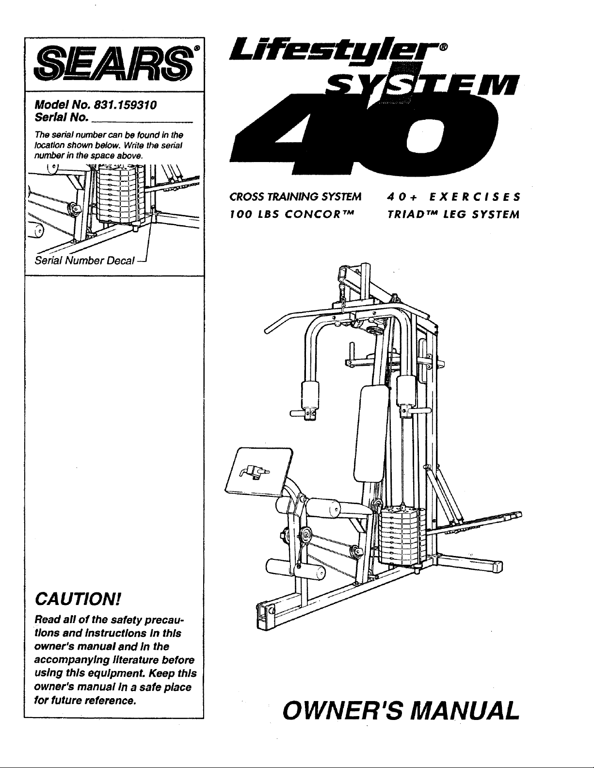
s Rs!
Model No. 831.159310
Serial No.
The serial number can be found in the
location shown below. Write the serial
number in the space above.
Serial Number Decal
CROSS TRAINING SYSTEM
100 LBS CONCOR TM
40+ EXERCISES
TRIAD TM LEG SYSTEM
CAUTION!
Read all of the safety precau-
tions and Instructions in this
owner's manual and in the
accompanying literature before
using this equipmenL Keep this
owner's manual in a safe place
for future reference.
OWNER'S MANUAL
Page 2
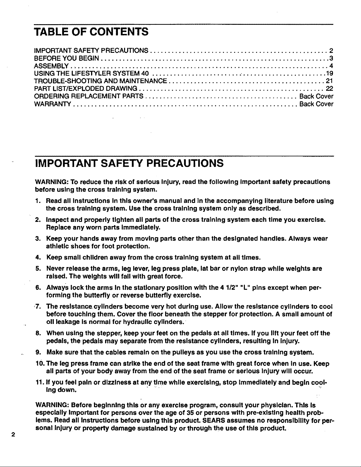
TABLE OF CONTENTS
IMPORTANT SAFETY PRECAUTIONS ................................................. 2
BEFORE YOU BEGIN ............................................................... 3
ASSEMBLY.. ..................................................................... 4
USING THE LIFESTYLER SYSTEM 40 ......................... ........................ 19
TROUBLE-SHOOTING AND MAINTENANCE ........................................... 21
PART LIST/EXPLODED DRAWING ................................................... 22
ORDERING REPLACEMENT PARTS .......................................... Back Cover
WARRANTY .............................................................. Back Cover
- IMPORTANT SAFETY PRECAUTIONS
WARNING: To reduce the risk of serious Injury, read the following Important safety precautions
before using the cross training system.
1. Read all Instructions In this owner's manual and in the accompanying literature before using
the cross training system. Use the cross training system only as described.
2. Inspect and properly tighten all parts of the cross training system each time you exercise.
Replace any worn parts Immediately.
3. Keep your hands away from moving parts other than the designated handles. Always wear
athletic shoes for foot protection.
4. Keep small children away from the cross training system at all times.
5. Never release the arms, leg lever, leg press plate, lat bar or nylon strap while weights are
raised. The weights will fall with great force.
6. Always lock the arms In the stationary position with the 4 1/2" "L" pins except when per-
forming the butterfly or reverse butterfly exercise.
,7. The reslstanne cylinders become very hot during use. Allow the resistance cylinders to cool
before touching them. Cover the floor beneath the stepper for protection. A small amount of
oll leakage Is normal for hydraulic cylinders.
8. When using the stepper, keep your feet on the pedals at all times. If you lift your feet off the
pedals, the pedals may separate from the resistance cylinders, resulting In Injury.
9. Make sure that the cables remain on the pulleys as you use the cross training system.
10. The leg press frame can strike the end of the seat frame with great force when In use. Keep
all parts of your body away from the end of the seat frame or serious Injury will occur.
11. If you feel pain or dizziness at any t!me while exercising, stop Immediately and begin cool-
Ing down. _'
WARNING: Before beglnnlng thls or any exerclse program, consult your physlclan. Thls Is
especlally Important for persons over the age of 35 or persons wlth pre-exlsUng health prob-
lems. Read all InstrucUons before uslng thls product. SEARS assumes no responslblllty for per-
sonal Injury or property damage sustalned by or through the use of thls product.
Page 3
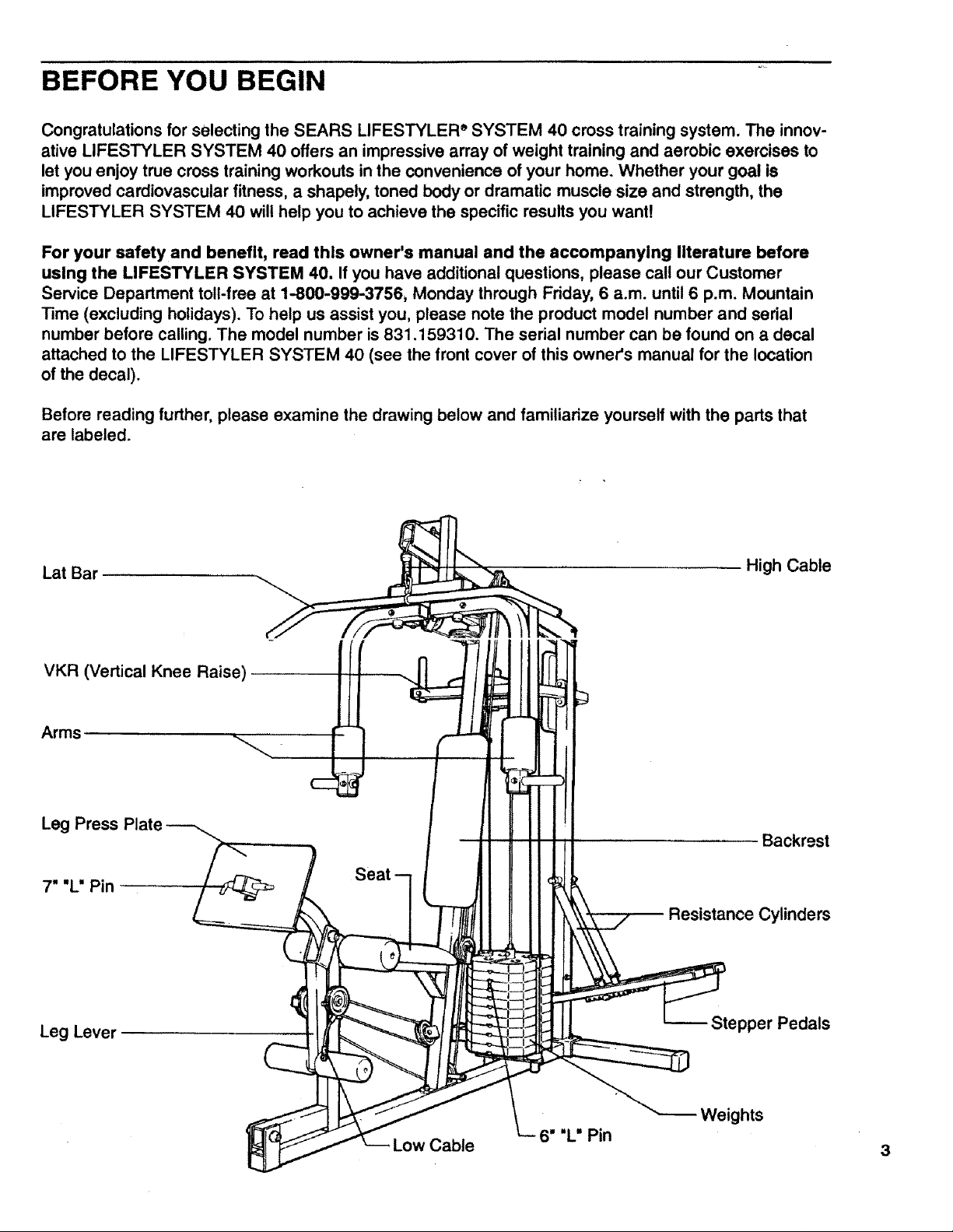
BEFORE YOU BEGIN
Congratulations for selecting the SEARS LIFESTYLER e SYSTEM 40 cross training system. The innov-
ative LIFESTYLER SYSTEM 40 offers an impressive array of weight training and aerobic exercises to
let you enjoy true cross training workouts in the convenience of your home. Whether your goal is
improved cardiovascular fitness, a shapely, toned body or dramatic muscle size and strength, the
LIFESTYLER SYSTEM 40 wil! help you to achieve the specific results you want!
For your safety and benefit, read this owner's manual and the accompanying literature before
using the LIFESTYLER SYSTEM 40, If you have additional questions, please call our Customer
Service Department toll-free at 1-800-999-3756, Monday through Friday, 6 a.m. until 6 p.m. Mountain
Time (excluding holidays). To help us assist you, please note the product model number and serial
number before calling. The model number is 831.159310. The serial number can be found on a decal
attached to the LIFESTYLER SYSTEM 40 (see the front cover of this owner's manual for the location
of the decal).
Before reading further, please examine the drawing below and familiarize yourself with the parts that
are labeled.
Lat Bar
VKR (Vertical Knee Raise)
Arms
Leg Press Plate
7" "L" Pin
High Cable
Backrest
Seat
Resistance Cylinders
Leg Lever
Low Cable
Stepper Pedals
3
Page 4

ASSEMBLY
Assembly requires two people and will take about 4 hours. The following tools (not Included) are
required: two 8" adjustable wrenches, a rubber mallet, a phillips screwdriver and a standard
screwdriver. Grease and a small bowl of soapy water are also required. As you assemble the
cross training system, read each step and examine each drawing carefully. Make sure that all parts
are oriented as shown In the drawings. Refer to the PART IDENTIFICATION (ID) CHART accompa-
nying this owner's manual for help identifying the small parts used in assembly. Due to the size and
weight of the cross training system, it should be assembled in the place where it will be used. Place all
parts of the cross training system in a cleared area and remove the packing materials; do not dispose
of the packing materials until the cross training system is completely assembled.
.
Press a 2" x 2" Outer Cap (36) onto each end
of the Stabilizer (73).
Insert two 5/16" x 2 3/4" Carriage Bolts (35)
and a 5/16" x 2 1/2" Carriage Bolt (22) up
through the Stabilizer (73).
Insert two 5/16" x 2 1/2" Carriage Bolts (22) up
through the Base (69). Slide the-end of the
Base over the two 5/16" x 2 3/4" Carriage
Bolts (35) in the Stabilizer (73).
36
35
i
36
2. Slide the Rear Upright (74) over the two
5/16" x 2 3/4" Carriage Bolts (35) in the
Stabilizer (73) and Base (69). Make sure that
the Rear Upright is turned so the pedal axles
are on the indicated side. Attach the Rear
Upright with two 5/16" Nylock Nuts (4). Do not
fully tighten the Nylock Nuts yet.
3. Slide the end of the Brace (56) that has an
oblong hole in it over the 5/16" x 2 1/2"
Carriage Bolt (22) in the Stabilizer (73). Attach
the Brace with a 5/16" Nylock Nut (4). Do not
fully tighten the Nylock Nut yet.
Attach the other end of the Brace (56) tothe
Rear Upright (74) with a 5/16" x 2 1/2 wBolt
(20), 5/16" Washer (10) and 5/16" Nylock Nut
(4).
22
//74
.._ Pedal axles
"_ must be on
_4 this side
2;
73
Tighten all Nylock Nuts used In assembly
steps 1-3.
Page 5
o
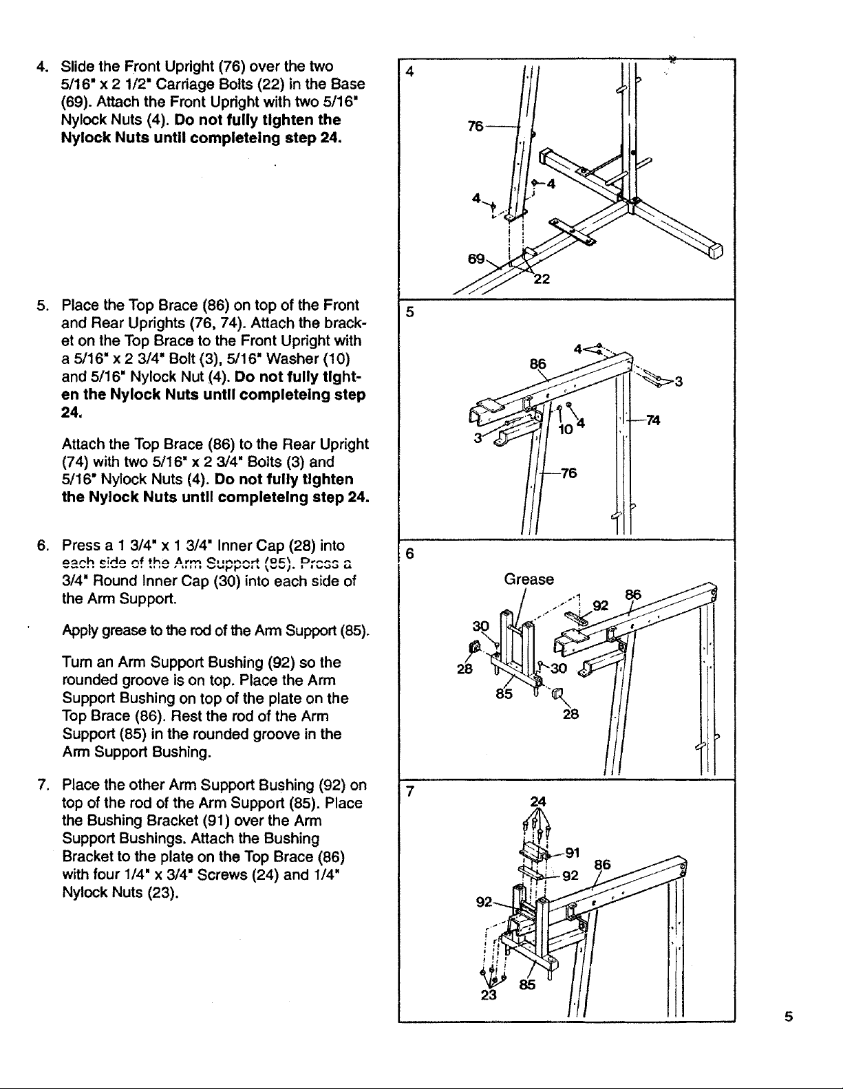
Slide the Front Upright (76) over the two
5/16" x 2 1/2" Carriage Bolts (22) in the Base
(69). Attach the Front Upright with two 5/16"
Nylock Nuts (4). Do not fully tighten the
Nylock Nuts until completeing step 24.
.
Place the Top Brace (86) on top of the Front
and Rear Uprights (76, 74). Attach the brack-
et on the Top Brace to the Front Updght with
a 5/16" x 2 3/4" Bolt (3), 5/16" Washer (10)
and 5/16" Nylock Nut (4). Do not fully tight-
en the Nylock Nuts until completeing step
24.
Attach the Top Brace (86) to the Rear Upright
(74) with two 5/16" x 2 3/4" Bolts (3) and
5/16" Nylock Nuts (4). Do not fully tighten
the Nylock Nuts until ¢ompletelng step 24.
4
5
,
Press a 1 3/4" x I 3/4" Inner Cap (28) into
3/4" Round Inner Cap (30) into each side of
the Arm Support.
Apply grease to the rod of the Arm Support (85).
Tum an Arm Support Bushing (92) so the
rounded groove is on top. Place the Arm
Support Bushing on top of the plate on the
Top Brace (86). Rest the rod of the Arm
Support (85) in the rounded groove in the
Arm Support Bushing.
.
Place the other Arm Support Bushing (92) on
top of the rod of the Arm Support (85). Place
the Bushing Bracket (91) over the Arm
Support Bushings, Attach the Bushing
Bracket to the plate on the Top Brace (86)
with four 1/4" x 3/4" Screws (24) and 1/4"
Nylock Nuts (23).
6
86
7
24
23
Page 6

Press two 1 3/4" x 1 3/4" Inner Caps (28) into
8. 8
each of the Arms (51).
Apply grease to the axles On the Arm Support
(85). Slide an Arm (51) onto the right axle.
Hold two 1 5/16" Retainer Rings (38) and a
1" Plastic Cap (37) against the lower end of
the axle. Make sure that the teeth on the
Retainer Rings bend downward. Tap the Re-
tainer Rings and Plastic Cap onto the axle.
Attach the other Arm (51) in the same manner.
Wet the lower ends of the Arms (51) and the
insides of the two 6 1/2" Foam Pads (84) with
soapy water. Slide the Foam Pads onto the
Arms until the Foam Pads are 3" from the
lower ends.
28
g.
Insert the end of a Handle (52) that has a
,_u_ th_ou it ;-'- tl-Ju -;-'-" ^'- _).
II tLU _._ I I U t;;;
II_IIL t"_1 III _=;.,_
5/16" Washer (10) and 5/16" x 3/8" Metal
Spacer (13) onto a 5/16" x 2 1/4" Bolt (14).
Insert the Bolt through the Arm and the
Handle. Slide another 5/16" Washer (10) onto
the Bolt and tighten a 5/16" Nylock Nut (4)
onto the Bolt.
Press a 1" Round Inner Cap (11) into the
Handle (52).- ....
Assemble a Handle (52) to the left Arm (51)
in the same manner.
Wet the Handles (52) with soapy water and
slide a Handle Grip (53) onto each Handle.
51
53
14
Page 7
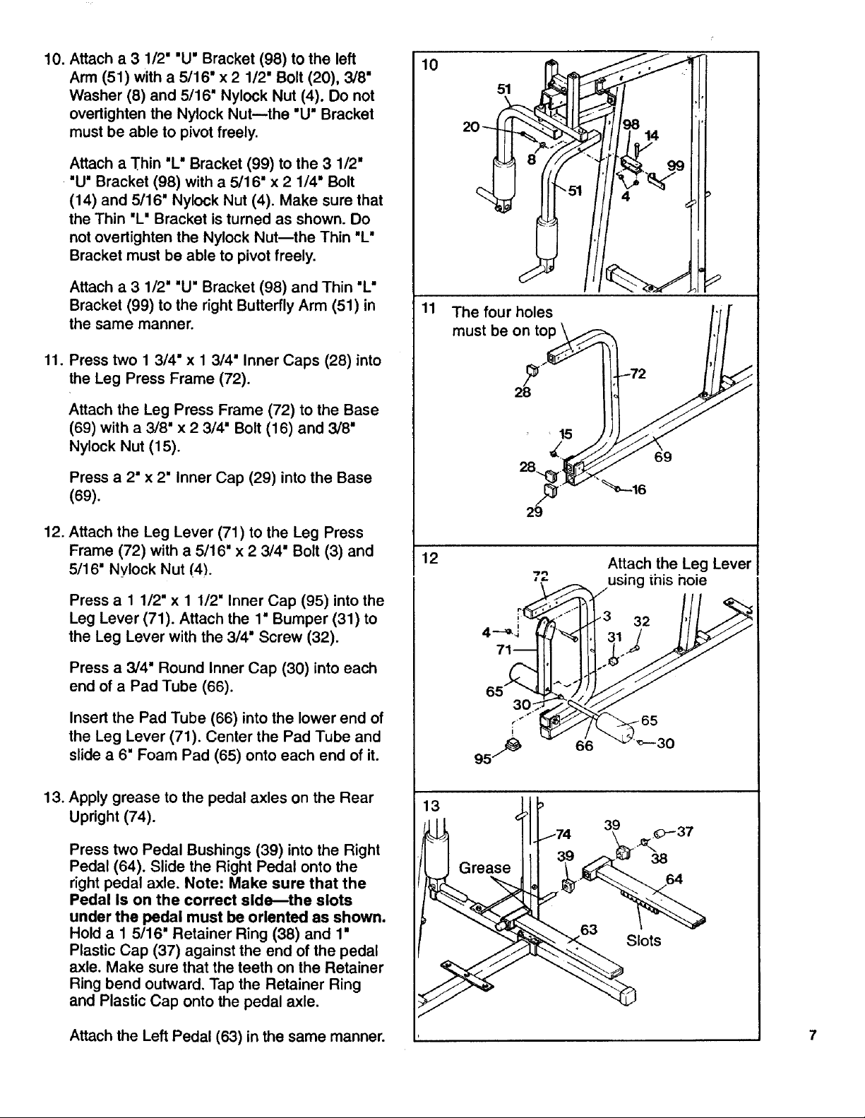
10. Attach a 3 1/2" "U" Bracket (98) to the left
Arm (51) with a 5/16" x 2 1/2" Bolt (20), 3/8"
Washer (8) and 5/16" Nylock Nut (4). Do not
overtighten the Nylock Nut--the "U" Bracket
must be able to pivot freely.
Attach a Thin "L" Bracket (99) to the 3 1/2"
"U" Bracket (98) with a 5/16" x 2 1/4" Bolt
(14) and 5/16" Nylock Nut (4). Make sure that
the Thin "L" Bracket is turned as shown. Do
not overtighten the Nylock Nut--the Thin "L"
Bracket must be able to pivot freely.
Attach a 3 1/2" "U" Bracket (98) and Thin "L"
Bracket (99) to the right Butterfly Arm (51) in
the same manner.
10
11
The four holes I'/
11. Press two 1 3/4" x 1 3/4" Inner Caps (28) into
the Leg Press Frame (72).
Attach the Leg Press Frame (72) to the Base
(69) with a 3/8" x 2 3/4" Bolt (16) and 3/8"
Nylock Nut (15).
Press a 2" x 2" Inner Cap (29) into the Base
(69).
12. Attach the Leg Lever (71) to the Leg Press
Frame (72) with a 5/16" x 2 3/4" Bolt (3) and
5/16" Nylock Nut (4).
Press a 1 1/2" x 1 1/2" Inner Cap (95) into the
Leg Lever (71). Attach the 1" Bumper (31) to
the Leg Lever with the 3/4" Screw (32).
Press a 3/4" Round Inner Cap (30) into each
end of a Pad Tube (66).
Insert the Pad Tube (66) into the lower end of
the Leg Lever (71). Center the Pad Tube and
slide a 6" Foam Pad (65) onto each end of it.
must be on t;_ ///
, 15
29_ 16
12
o 't- _ 7us=ng in=s hole
4--__ _ 31 / II L SJ
95 _ v 6"6 "_ _--30
Attach the Leg Lever
13. Apply grease to the pedal axles on the Rear
Upright (74).
Press two Pedal Bushings (39) into the Right
Pedal (64). Slide the Right Pedal onto the
right pedal axle. Note: Make sure that the
Pedal Is on the correct side--the slots
under the pedal must be oriented as shown.
Hold a 1 5/16" Retainer Ring (38) and 1"
Plastic Cap (37) against the end of the pedal
axle. Make sure that the teeth on the Retainer
Ring bend outward. Tap the Retainer Ring
and Plastic Cap onto the pedal axle.
Attach the Left Pedal (63) in the same manner.
13 J _
lots
Page 8

14,Place a Foot Pad (62) on the end of the Right
Pedal (64). Attach the Foot Pad with a 1/2"
Pan Screw (45).
Attach the other Foot Pad (62) to the Left
Pedal (63) in the same manner.
15.
Apply grease to the cylinder axles on the Rear
Upright (74).
Slide a Cylinder Spacer (48) and a Resistance
Cylinder (60) onto each cylinder axle. Hold a
1• Retainer Ring (47) and 5/8" Plastic Cap
(46) against the end of the left cylinder axle,
Make sure that the teeth on the Retainer Ring
bend outward, Tap the Retainer Ring and
Plastic Cap onto the cylinder axle. Attach a 1"
Retainer Ring (47) and 5/8" Plastic Cap (46)
to the right cylinder axle in the same manner,
45
63
,,_-- 46
15 _/Grea_e
16. Raise the Right Pedal (64) and rest it on the
hr:_ek_t _t fh_ Inw_r _nd nf th_ rinhf
Resistance Cylinder (60). Make sure that the
bracket is in one of the slots under the Pedal.
Rest the Left Pedal (63) on the bracket at the
lower end of the left Resistance Cylinder (60).
Make sure that the brackets are in the same
slots under both Pedals.
17, Attach the two VKR Arms (57) to the Rear
Upright (74) with two 5/16" x 2 3/4" Bolts (3)
and 5/16" Nylock Nuts (4),
Press a 1 1/2" x 1 1/2" Inner Cap (95) into
each VKR Arm (57),
16 I/ll IlL
i
17
95
95
60
64
63
57
4
57
Page 9

18. Attach a VKR Armrest (58) to each VKR Arm
(57) with two 1/4" x 2' Screws (9) and 1/4"
Washers (1).
Attach the VKR Backrest (59) to the Rear
Upright (74) with two 1/4" x 2 1/2" Screws (2)
and 1/4" Washers (1).
18 ._
19. Press a 1" Round Inner Cap (11) into each
end of a Handle (52).
Insert the end of the Handle (52) that has a
hole through it into the left VKR Arm (57).
Slide a 5/16" Washer (10) onto a 5/16" x 2"
Bolt (12). Insert the Bolt through the VKR
Arm and the Handle. Slide another 5/16"
Washer (10) onto the Bolt and tighten a 5/16"
Nylock Nut (4) onto the Bolt.
Assemble a Handle (52) to the right VKR Arm
(57) in the same manner.
20. Press a 1 1/2" x 1 1/2" Inner Cap (95) into the
RARt F'rAm_. (R7) Attsoh the ReS! P!Ste (_RS)
to the Seat Frame with the 1/4" x 2" Carriage
Bolt (25), a 1/4" Washer (1) and a 1/4" Nylock
Nut (23).
Attach the Seat (77) to the Seat Plate (68)
with two 1/4" x 3/4" Screws (24).
Attach the Seat (77) to the Seat Frame (67)
with a 1/4" x 2 _Screw (9) and 1/4" Washer (1).
19
_11 I"L--52
2O
77
' 1
67 _23
21. Attach the Seat Frame (67) to the Front
Upright (76) with two 5/16" x 2 3/4" Bolts (3),
5/16" Washers (10) and 5/16" Nylock Nuts
(4).
Press a 3/4" Round Inner Cap (30) into each
end of a Pad Tube (66).
Insert the Pad Tube (66) into the Seat Frame
(67). Center the Pad Tube and slide a 6" Foam
Pad (65) onto each end of it.
21
67
4<
65
9
Page 10

22. Attach the Backrest (78) to the Front Upright
(76) with two 1/4" x 2 1/2" Screws (2) and
1/4" Washers (1).
23.
Insert a 3/8" x 2 3/4" Bolt (16) into one side of
the Top Brace (86). Slide a 3/8" x 3/8" Metal
Spacer (6) onto the Bolt. Lay the ball-end of
the Short Cable (94) over a 3 1/2"Pulley (55).
Slide the Pulley and another 3/8" x 3/8" Metal
Spacer (6) onto the Bolt. Insert the Bolt
through the other side of the Top Brace and
tighten a 3/8" Nylock Nut (15) onto the Bolt.
Attach the 2" Metal Spacer (49) inside the
Top Brace (86) with a 5/16" x 2 3/4" Bolt (3)
and 5/16" Nylock Nut (4). Make sure that the
Short Cable (94) is under the 2" Metal Spacer.
22
23
15 86
6 "_" 3
94
24.
Insert the other end of the Short Cable (94)
(86) and the Front Upright (76). Lay the Cable
over a 3 1/2" Pulley (55). Hold the Pulley in
the upper end of the Front Upright.
Slide a 3/8" Washer (8) and 3/8" x 3/8" Metal
Spacer (6) onto a 3/8" x 3 1/2" Bolt (5). Insert
the Bolt through the Top Brace (86), Front
Upright (76) and 3 1/2" Pulley (55). Slide
another 3/8_x 3/8" Metal Spacer (6) and 3/8"
Washer (8) onto the Bolt and tighten a 3/8"
Jam Nut (7) onto the Bolt.
Tighten all Nylock Nuts used in assembly
steps 4-5.
25. Attach two.3 1/2" Pulleys (55) to the two "1'
Plates (75) with 3/8" x 1 3/4" Bolts (26) and
3/8" Nylock Nuts (15). Make sure that the
Pulleys are attached to the holes in the ends
of the "1" Plates.
24 r,,
0 ,J,J \
7_ ........... ,,
, \
25
55
15
75
55
r
,26
75
10
Page 11

26. Route the end of the Short Cable (94) around
the indicated 3 1/2" Pulley (55) in the "t"
Plates (75).
Insert a 3/8" x 2 3/4" Bolt (16) into one side of
the Top Brace (86). Slide a 3/8" x 3/8" Metal
Spacer (6) onto the Bolt. Lay the Short Cable
(94) over a 3 1/2" Pulley (55). Slide the Pulley
and another 3/8" x 3/8" Metal Spacer (6) onto
the Bolt. Insert the Bolt through the other side
of the Top Brace and tighten a 3/8" Nylock Nut
(15) onto the Bolt.
26
86
15
27. Press the Domed Inner Cap (34) into the
lower end of the Weight Selector (82).
Slide a Weight (79) onto the upper end of the
Weight Selector (82). Make sure that the
Weight is turned so the pin groove is down-
ward.
Insert the end of the Short Cable (94) into the
upper end of the Weight Selector (82) and
attach it with the 5/16" x 1 1/2" Bolt (33) and
a 5/16" Nylock Nut (4).
28. Wrap the ball-end of the Long Cable (93)
under a 3 1/2" Pulley (55). Attach the Pulley
to the Leg Press Frame (72) with a 3/8" x
3 1/2" Bolt (5), 3/8" Washer (8) and 3/8"
Nylock Nut (15). Make sure that the Cable is
between the Pulley and the pin on the Leg
Press Frame.
27
/
Pin Groove
28
11
Page 12

Attach a 3" "U" Bracket (97) to the Front
29. 29
Upright (76) with a 5/16" x 4" Bolt (27), 5/16"
Washer (10) and 5/16" Nylock Nut (4). The
Nylock Nut should be threaded onto the
Bolt four complete turns. The cabling will
be too short If the Nylock Nut Is overtlght-
ened.
Wrap the Long Cable (93) around a 4 1/2"
Pulley (54) as shown. Attach the Pulley to the
3" "U" Bracket (97) with a 3/8" x 1 3/4" Bolt
(26) and 3/8" Nylock Nut (15).
30. Slide a Plastic Cable Guide (18) and a 3 1/2"
Pulley (55) onto a 3/8" x 3 1/2" Bolt (5). Insert
the Bolt into the Leg Lever (71). Slide a 3/8"
Washer (8) onto the Bolt and tighten a 3/8"
Nylock Nut (15) onto the Bolt.
Pull back the Plastic Cable Guide (18) and
wrap the Long Cable (93) around the 3 1/3"
Pulley (55). Turn the Plastic Cable Guide so
it holds the Cable on the Pulley.
31.
Slide a Plastic Cable Guide (18) and a 3 1/2"
Pulley (55) onto a 3/8" x 3 3/4" Bolt (21).
Insert the Bolt into the tube on the Base (69)
and tighten a 3/8" Nylock Nut (15) onto the
Bolt.
Pull back the Plastic Cable Guide (18) and
wrap the Long Cable (93) under the 3 1/3"
Pulley (55). Turn the Plastic Cable Guide so
it holds the Cable on the Pulley.
93
26
3O
31
18
55
21 69
15
12
32.
Route the Long Cable (93) over the 3 1/2"
Pulley (55) at the lower end of the "1" Plates
(75).
Slide a Plastic Cable Guide (18) and a 3 1/2"
Pulley (55) onto a 3/8" x 3 3/4" Bolt (21).
Insert the Bolt into the tube on the Front
Upright (76) and tighten a 3/8" Nylock Nut
(15) onto the Bolt.
Pull back the Plastic Cable Guide (18) and
wrap the Long Cable (93) under the 3 1/3"
Pulley (55). Turn the Plastic Cable Guide so
it holds the Cable on the Pulley.
Page 13

33. Attach a Thick "L" Bracket (100) to the bracket
on the Top Brace (86) with a 5/16" x 3 1/4"
Bolt (19) and 5/16' Nylock Nut (4). Make sure
that the Thick "L" Bracket is turned as shown.
Slide a Plastic Cable Guide (18) and a 3 1/2"
Pulley (55) onto a 3/8" x I 3/4" Bolt (26). Insert
the Bolt into the Thick "L" Bracket (100) and
tighten a 3/8" Nylock Nut (15) onto the Bolt.
Pull back the Plastic Cable Guide (18) and
lay the Long Cable (93) over the 3 1/2" Pulley
(55). Turn the Plastic Cable Guide so it holds
the Cable on the Pulley.
34. Slide a Plastic Cable Guide (18) and a 3 1/2"
Pulley (55) onto a 3/8" x 2" Bolt (44). Insert the
Bolt into the Thin "L" Bracket (99) on the left
Arm (51) and tighten a 3/8" Nylock Nut (15)
onto the Bolt.
Pull back the Plastic Cable Guide (18) and
wrap the Long Cable (93) around the 3 1/2"
Pulley (55). Turn the Plastic Cable Guide so
it holds the Cable on the Pulley.
33
55
34
93
35. Attach a 3" "U" Bracket (97) to the Front
Upright (76) with a 5/16' x 4" Bolt (27), 5/16"
Washer (10) and 5/16' Nylock Nut (4). The
Nylock Nut should be threaded onto the
Bolt four complete turns. The cabling will
be too short If the Nylock Nut Is overtlght-
ened.
Wrap the Long Cable (93) around a 4 1/2"
Pulley (54). Attach the Pulley to the 3" "U"
Bracket (97) with a 3/8" x 1 3/4" Bolt (26) and
3/8" Nylock Nut (15).
36. Slide a Plastic Cable Guide (18) and a 3 1/2"
Pulley (55) onto a 3/8" x 2" Bolt (44). Insert the
Bolt into the Thin "L" Bracket (99) on the right
Arm (51) and tighten a 3/8" Nylock Nut (15)
onto the Bolt. Note: Make sure that the
3 1/2" Pulley is attached on the side of the
Thin "L" Bracket as shown.
Pull back the Plastic Cable Guide (18) and
wrap the Long Cable (93) around the 3 1/2"
Pulley (55). Turn the Plastic Cable Guide so
it holds the Cable on the Pulley,
35
36
54 97.
93
15 99 _93
\
\
\
\
\
\
\
13
Page 14

37. Slide the end of the Long Cable (93) onto the
end of the 3/8" x 3 1/2" Bolt (5) in the Top
Brace (86). Slide a 3/8" Washer (8) onto the
Bolt and tighten the 3/8" Jam Nut (7) onto the
Bolt. Note'- The 3/8" x 3 1/2" Bolt (5) Is the
Bolt that was used In assembly step 24.
The Bolt will already have one Nut thread-
ed onto It. The step described above will
attach the Long Cable to the remaining
threads so there will be two Nuts on the
Bolt.
37
7
86
Attach the Cable to
the same Bolt that
was used in
24
38. Slide the Leg Press Plate (70) onto the end of
the Leg Press Frame (72). Insert the 7" "L"
Pin (40) through the Leg Press Plate and one
of the four holes in the Leg Press Frame.
39. Find the lower ends of the two Weight Guides
(83) (there are holes near the upper ends of
the Weight Guides). Slide a Weight Bumper
(50) onto the lower end of each Weight
Guide. Insert the Weight Guides into the
bracket on the Base (69).
Fit theWeight Guides (83) into the recesses
in the sides of the Weight (79) on the Weight
Selector (82).
38
72
40
70
39
14
40. Insert a 5/16" x 4 1/4" Bolt (41) through the
upper end of one of the Weight Guides (83).
Slide a 2 5/8" Metal Spacer (42) onto the Bolt
and insert the Bolt into the Top Brace (86).
Tighten a ,_/16" Nylock Nut (4) onto the Bolt.
Attach the other Weight Guide (83) to the Top
Brace (86) in the same manner.
4O
41
42 86
41
Page 15

41. Raise the Weight Selector (82). Place the
remaining nine Weights (79) on the Weight
Guides (83) by tipping the Weights as shown.
Make sure that the Weights are turned so all
of the pin grooves are under the Weights and
are on the same side. Lower the Weight
Selector into the Weights.
41
Pin Grooves
42. Open a Weight Sleeve (80) and close it
around one of the Weight Guides (83). Close
the other Weight Sleeve (80) around the
other Weight Guide. Turn the Weight Sleeves
so the hinged sides are toward each other.
43. Tip the top Weight (79) as shown. Fit the low
_Ju_ Ui L;_ VV_;*yllL ZllLU _ VV_,lyllL ,._l_t_vt_ _ou),
Fit the high side of the Weight into the other
Weight Sleeve. Press the Weight and the
Weight Sleeves down until they are resting
on top of the other Weights.
42
43
8O
II \\\/I
44. Hold the open end of a Weight Sleeve Clip
(81) against one of the Weight Sleeves (80)
as shown. Firmly press the Weight Sleeve
Clip until it snaps around the Weight Sleeve.
Press the other Weight Sleeve Clip (81) onto
the other Weight Sleeve (80) in the same
manner.
44
15
Page 16

45. Press a 1" Round Inner Cap (11)into each
end of the I.at Bar (87).
46.
Remove the "HIGH PULLEY" decal from the
Decal Sheet (not shown). Apply the decal to
the side of the Top Brace (86).
Remove the "DUAL FUNCTION PRESS
ARM" decal from the Decal Sheet (not
shown). Center the decal on the front of the
Arm Support (85).
Remove the "ACTUAL RESISTANCE FOR
BENCH PRESS..." decal from the Decal
Sheet (not shown). Apply the decal to the left
Arm (51).
45
46
"HIGH PULLEY"
"DUAL
PRESS ARM"
"ACTU
RESISTANCE
FOR BENCH
PRESS..."
11
86
85
47,
Remove the "VERTICAL KNEE RAISE" decal
from the. De._._l Rhe.et (ncJt ._hnwn) Apply thp.
decal to the side of the right VKR Arm (57).
48. Remove the "LOW PULLEY" decal from the
Decal Sheet (not shown). Apply the decal to
the Leg Press Frame (72) below the indicated
3 1/2" Pulley (55).
47
!
57
"VERTICAL
KNEE RAISE"
48
16
Page 17

49. Remove the "TRIAD LEG SYSTEM" decal
from the Decal Sheet (not shown). Apply the
decal to the corner of the Leg Press Plate
(70).
49
"TRIAD LEG SYSTEM"
50. Remove the ten small decals numbered "10"
through "100" from the Decal Sheet (not
shown). Apply the decals to the ten Weights
(79) in the indicated locations. The decal
numbered "10" should be applied to the top
Weight; the decal numbered "100" should be
applied to the bottom Weight.
51. Remove the "INDEPENDENT ACTION
shown). Apply the decal to the Rear Upright
(74). The lower end of the decal should be
aligned with the cylinder axles.
Remove the "HOT" decal from the Decal
Sheet (not shown). Apply the decal to the
Rear Upright (74) above the indicated 5/16"
Nytock Nut (4).
50
51
"INDEPENDENTACTION
STEPPER"
Cylinder Axles
Remove the two "SPEED LINK" decals from
the Decal Sheet (not shown). Apply the
decals to the Left and Right Pedals (63, 64).
Make sure that both decals are turned so the
words "FAST" are toward the Upright (74).
"SPEED LINK"
Note: The words
"FAST" must be
at this end.
64
17
Page 18

52. Make sure that all parts are properly tightened. The use of all remaining parts will be explained in
USING THE LIFESTYLER SYSTEM 40, beginning on page 19 of this owner's manual.
WARNING: For your safety and benefit, attach all decals before using the cross training sys-
tem,
Before using the cross training system, make sure that both of the cables are properly routed. Pull
the ends of both cables a few times to make sure that the cables move smoothly over the pulleys.
Move the butterfly arms and the leg press plate a few times. If either of the cables does not move
smoothly, locate and correct the problem before using the cross training system. IMPORTANT: If
the cables are not properly routed, they may be permanently damaged when used with
heavy weights.
18
Page 19

USING THE LIFESTYLER SYSTEM 40
The instructions below describe how each part of the cross training system can be adjusted. See the
EXERCISE GUIDE accompanying this owner's manual to see how the cross training system should be
set up for each individual exercise.
CHANGING THE WEIGHT SE'n'ING
The weight setting of the cross training system
can be changed from a minimum of 10 pounds to
a maximum of 100 pounds, in increments of 10
pounds. To select a weight setting, insert the
6" "L" Pin (96) under a Weight (79) and through
the Weight Selector (82). Turn the end of the Pin
downward.
Note: Due to the design of the cables and pul-
leys, the amount of weight will be DOUBLED
when the arms are used in the press arm
mode, and TRIPLED when the leg press plate
is used.
CHANGING THE STEPPING RESISTANCE
To vary the intensity of your workouts, the resis-
tance of the stepper pedals can be changed. To
change the resistance, lift the Pedals (63, 64) off
the brackets at the lower ends of the Resistance
Cylinders (60). Move the brackets to different
slots under the Pedals. Make sure that the brack-
ets are in the same slots under both Pedals. The
farther the Resistance Cylinders are from the
Rear Upright (74), the greater the resistance will
be.
ADJUSTING THE LEG PRESS PLATE
The Leg Press Plate (70) can be adjusted to any
of four positions. To change the position, first
remove the 7" "L" Pin (40). Move the Leg Press
Plate forward or backward and insert the "L" Pin
through the Leg Press Plate and the Leg Press
Frame (72).
/
60
64
63
70
40
72
For certain exercises, the Leg Press Plate (70)
should be removed from the Leg Press Frame
(72).
19
Page 20

USINGTHEARMSINTHEBUTrERFLYMODE
To use the Arms (51) in the butterfly mode, the
Arm Support (85) must be locked in a stationary
position. To lock the Arm Support, insert a 4 1/2"
"L" Pin (43) down through the center of the Arm
Support and the bracket on the Front Upright (76).
Set the other 4 1/2" "L" Pin (43) aside.
USING THE ARMS IN THE PRESS MODE
85
\\'
To use the Arms (51) in the press mode, the
Arms must be locked in a stationary position.
Insert the two 4 1/2" "L" Pins (43) down through
the Arm Support and the Arms. IMPORTANT:
Always lock the arms in the stationary posi-
tion with the 4 112" "L" Pins except when per-
forming the butterfly or re-verse butterfly exer-
cise.
ATTACHING THE LAT BAR OR NYLON STRAP
TO THE H!GH C.A.BLE
The Lat Bar (87) can be attached to the high
cable with a Cable Clip (89). For some exercises,
the Chain (88) must be attached between the Lat
Bar and the high cable with two Cable Clips. The
distance between the Lat Bar and the high cable
can be adjusted by attaching the Cable Clips
closer together o_rfarther apart along the Chain.
43
<
The Nylon Strap (90) can be attached to the high
cable in the same manner.
ATTACHING THE LAT BAR OR NYLON STRAP
TO THE LOW CABLE
The Lat Bar (87-) can be attached to the low cable
with a Cable Clip (89). For some exercises, the
Chain (88) must be attached between the Lat Bar
and the low cable with two Cable Clips.-The dis-
tance between the Lat Bar and the low cable can
be adjusted by attaching the Cable Ciips closer
together or farther apart along the Chain.
The Nylon Strap (90) can be attached to the high
20 cable in the same manner.
87
Page 21

TROUBLE-SHOOTING AND MAINTENANCE
Inspect and properly tighten all parts of the cross training system each time you exercise. Replace any
wom parts immediately. The cross training system can be cleaned using a damp cloth and mild non-
abrasive detergent. Do not use solvents.
ADJUSTING THE CABLES
If there is too much slack in the cables, the
cables can be adjusted. To tighten the cables,
find the 5/16" Nylock Nut (4) near the lower end
of the Front Upright (76). To tighten the cables,
hold the 5/16" x 4" Bolt (27) and turn the Nylock
Nut clockwise. If the cables cannot be tightened
enough by turning the Nylock Nut, see the
instructions below.
Locate the two 3 1/2" Pulleys (55) attached to the
"1" Plates (75). The 'T' Plates have three adjust-
ment holes for tightening the cables. Remove the
3/8" Nylock Nut (15) and 3/8" x 1 3/4" Bolt (26)
attaching the lower Pulley to the 'T' Plates. Attach
the Pulley to the next higher hole in the "1"
Plates. Turn the 5/16" Nylock Nut (4) clockwise
umii the cabies are tight (see Orawing i).
27
If the cables still cannot be tightened enough,
see the back cover of this owner's manual to
order new cables.
-26
55 _
21
Page 22

PART LIST/EXPLODED DRAWING--Model No. 831.159310
Key Part Key Part
No. No. Qty. Description No. No. Qty. Description
1 014127 10 1/4" Washer 53 112444 2 Handle Grip
2 013341 4 1/4" x2 1/2"Screw 54 113815 2 4 1/2" Pulley
3 113744 11 5/16" x 2 3/4" Bolt 55 108192 12 3 1/2" Pulley
4 012082 29 5/16" NylockNut 56 113697 1 Brace
5 104049 3 3/8"x3 1/2" Bolt 57 113698 2 VKR Arm
6 113745 6 1/2" x 3/8" Metal Spacer 58 113669 2 VKR Armrest
7 012108 2 3/8" Jam Nut 59 113700 1 VKR Backrest
8 105495 8 3/8" Washer 60 109398 2 Resistance Cylinder
9 013498 5 1/4" x-2" Screw 61 112323 4 Cylinder Bushing
10 014073 14 5/16" Washer 62 112277 2 Foot Pad
11 103343 8 1" Round Inner Cap 63 113861 1 Left Pedal
12 013442 2 5/16" x 2" Bolt 64 113860 1 Right Pedal
13 111470 4 3/8" x 3/8" Metal Spacer 65 113704 4 6" Foam Pad
14 102864 4 5/16" x2 1/4" Bolt 66 108726 2 PadTube
15 012108 14 3/8" Nylock Nut 67 113706 1 Seat Frame
16 113748 2 3/8" x 2 3/4" Bolt 68 113816 1 Seat Plate
17 113655 1 Decal Sheet 69 113709 1 Base
18 113662 6 Plastic Cable Guide 70 113857 1 Leg Press Plate
19 013231 1 5/16" x 3 1/4" B.olt 71 113710 1 Leg Lever
20 103053 3 5/16" )( 2 1/2" Bolt 72 113711 1 Leg Press Frame
21 106465 2 3/8" x 3 3/4" Bolt 73 113712 1 Stabilizer
22 100994 3 5/16" x 2 1/2" Carriage Bolt 74 113713 1 Rear Upright
23 012090 8 1/4" NylockNut 75 113760 2 "1" Plate
24 013456 6 1/4" x 3/4" Screw 76 113714 1 Front Upright
25 013330 1 1/4" x 2" Carriage Bolt 77 113715 1 Seat
26 013564 5 3/8" x 1 3/4" Bolt 78 113716 1 Backrest
"_7 Al':ll:;;_q 9 _/1R" v A" _,1+ 79 4na,_a,_ 10 _^r^;_.+
28 113666 8 1 3/4" x 1 3/4" Inner Cap 80 109976 2 Weight Sleeve
29 108874 1 2" x 2" inner Cap 81 112608 2 Weight Sleeve Clip
30 113667 6 3/4" Round Inner Cap 82 113699 1 Weight Selector
31 113668 1 1" Bumper 83 113719 2 Weight Guide
32 107428 1 3/4" Screw 84 113720 2 6 1/2" Foam Pad
33 013210 1 5/16" x 1 1/2" Bolt 85 113721 1 Arm Support
34 110726 1 Domed Inner Cap 86 113738 1 Top Brace
35 113814 2 5/16" x 2 3/4" Carriage Bolt 87 113739 1 Lat Bar
36 105723 2 . 2" x 2" Outer Cap 88 105315 1 Chain
37 113761. 4 1" Plastic Cap 89 103087 3 Cable Clip
38 113821 4 . 1 5/16" Retainer Ring 90 107048 1 Nylon Strap
39 112275 2 Pedal Bushing 91 113740 1 Bushing Bracket
40 113759 1 7""L" Pin 92 113741 2 Arm Support Bushing
41 113752 2 5/16" x4 1/4" Bolt 93 113650 1 Long Cable
42 113685 2 2 5/8" Metal Spacer 94 113649 1 Short Cable
43 105977 2 4 1/2""L" Pin 95 103833 4 1 1/2" x 1 1/2" Inner Cap
44 013580 _2 3/8" x 2" Bolt 96 113754 1 6""L"Pin
45 013162 2 1/2" Pan Screw 97 113755 2 3" "U" Bracket
46 115406 2 5/8" Plastic Cap 98 113758 2 3 1/2" "U" Bracket
47 112310 2 1" Retaining Ring 99 113756 2 Thin"L" Bracket
48 112359 2 Cylinder Spacer 100 113757 1 Thick "L" Bracket
49 113753 1 2" Metal Spacer # 113517 1 Owner's Manual
50 105433 2 Weight Bumper # 113663 1 Part Identification Chart
51 113694 2 Arm # 113822 1 Exercise Manual
52 113696 4 Handle
22 Note: "#" indicates a non-illustrated part. Specifications are subject to change without notice. Rev. 10/93
Page 23

55
44
55
4
42
86
87
4
58
42
57
23
I
84
14 |15_ 97
54
28
6
4 10
47
s
48
61
20
33
55
10
>
I
I i
I I
I
I
73
16
69
39
39
\ 37
45
23
Page 24

ORDERING REPLACEMENT PARTS
Each SYSTEM has its own MODEL NUMBER. Always mention this MODEL NUMBER when request-
ing service or repair parts for your SYSTEM.
All parts listed herein can be ordered through SEARS, ROEBUCK AND CO. SERVICE CENTERS and
most SEARS RETAIL STORES. If parts you need are not stocked locally, your order will be transmitted
to a SEARS PARTS DISTRIBUTION CENTER for handling.
WHEN ORDERING REPAIR PARTS, ALWAYS GIVE THE FOLLOWING INFORMATION:
1. The MODEL NUMBER -of the product (831.159310).
2. The NAME of the product (SEARS LIFESTYLER ®SYSTEM 40 cross training system).
3. The PART NUMBER of the part(s) from the PART IDENTIFICATION (ID) CHART accompanying
this owner's manual.
4. The DESCRIPTION of the part(s) from the PART IDENTIFICATION CHART accompanying this
owner's manual.
Your SEARS SYSTEM has added value when you consider that SEARS has service units nationwide,
staffed with SEARS trainedtechnici'ans specifically trained on SEARS products, having the pads, tools
and equipment to ensure that we meet our pledge to you: "We service what we sell."
Should you ever need repair service or pads, call toll free:
For repair service: 1-800-4-REPAIR (1-800-473-7247)
For repair parts: !-800-FON-PART (I-800-366-7278)
I
For 90 days from the date of purchase, when proper assembly and maintenance procedures
detailed'in the .Owner's Manual are followed, SEARS will, free of charge, repair or replace and
install a replacement part for any defective partl when this cross training system is used in a
normal manner.
This warranty does not apply when this cross training system is used for commercial or rental
purposes.
SERVICE-IS AVAILABLE SIMPLY BY CONTACTING YOUR NEAREST SEARS SERVICE
CENTER/DEPARTMENT IN THE UNITED STATES.
This warranty gives you specific legal rights, and you may also have other rights which vary
from state to state. - '
FULL 90 DAY WARRANTY
u
I
SEARS_ ROEBUCK AND CO., DEPT. 817WA,
3333 BEVERLY ROAD, HOFFMAN ESTATES, IL 60179
Part No. 113517 10/93 © Sears, Roebuck and Co. Printed in Canada
 Loading...