

ProFlow PF-OXY1, 5 Technical Manual

© 2016 erie water treatment TM-EN-PF-OXY-Rev2016.08
Technical Manual
WATER FILTER - Fe, Mn, H2S
Models: PF-OXY1
PF-OXY+1
PF-OXY1,5
PF-OXY+1,5

TABLE OF CONTENT & INSTALLATION RECORD
Page 2
Table of content & Installation record ..................................................................................Page 2
Warning & Safety instructions ..............................................................................................Page 3
Operating conditions & Requirements .................................................................................Page 4
Assembly..............................................................................................................................Page 6
Installation ...........................................................................................................................Page 8
Commissioning .....................................................................................................................Page 9
Electronic control panel .......................................................................................................Page 10
Maintenance ........................................................................................................................Page 13
Troubleshooting ...................................................................................................................Page 14
Electrical wiring diagrams ....................................................................................................Page 16
Default configuration parameter settings.............................................................................Page 17
Composition overview .........................................................................................................Page 18
Exploded view - PF-OXY1 & PF-OXY+1 - System ....................................................................Page 20
Exploded view - PF-OXY1 & PF-OXY+1 - Timer assembly .......................................................Page 22
Exploded view - PF-OXY1 & PF-OXY+1 - Valve body...............................................................Page 24
Exploded view - PF-OXY1,5 & PF-OXY+1,5 - System ...............................................................Page 26
Exploded view - PF-OXY1,5 & PF-OXY+1,5 - Timer assembly..................................................Page 28
Exploded view - PF-OXY1,5 & PF-OXY+1,5 - Valve body .........................................................Page 30
Exploded view - PF-OXY1,5 & PF-OXY+1,5 - Piston assembly .................................................Page 32
Technical data - PF-OXY1 & PF-OXY+1 ...................................................................................Page 33
Technical data - PF-OXY1,5 & PF-OXY+1,5 .............................................................................Page 34

WARNING & SAFETY INSTRUCTIONS
Page 3
Before you begin the installation of the appliance, we advise you read
and carefully follow the instructions contained in this manual. It contains
important information about safety, installation, use and maintenance of
the product. The actual system that you have received, may differ from
the pictures/illustrations/descriptions in these Instructions.
Failure to follow the instructions could cause personal injury or damage
to the appliance or property. Only when installed, commissioned and
serviced correctly, the appliance will offer you many years of trouble-free
operation.
The appliance is intended to ‘filter’ the water, meaning it will remove
specific undesired substances; it will not necessarily remove other
contaminants present in the water. The appliance will not purify polluted
water or make it safe to drink!
Installation of the appliance should only be undertaken by a competent
person, aware of the local codes in force. All plumbing and electrical
connections must be done in accordance with local codes.
Before setting up the appliance, make sure to check it for any externally
visible damage; do not install or use when damaged.
Use a hand truck to transport the appliance. To prevent accident or
injury, do not hoist the appliance over your shoulder. Do not lay the
appliance on its side.
Keep these Instructions in a safe place and ensure that new users are
familiar with the content.
The appliance is designed and manufactured in accordance with current
safety requirements and regulations. Incorrect repairs can result in
unforeseen danger for the user, for which the manufacturer cannot be
held responsible. Therefore repairs should only be undertaken by a
competent technician, familiar and trained for this product.
In respect of the environment, this appliance should be disposed of in
accordance with Waste Electrical and Electronic Equipment
requirements. Refer to national/local laws and codes for correct recycling
of this appliance.
OPERATING CONDITIONS & REQUIREMENTS
Page 4
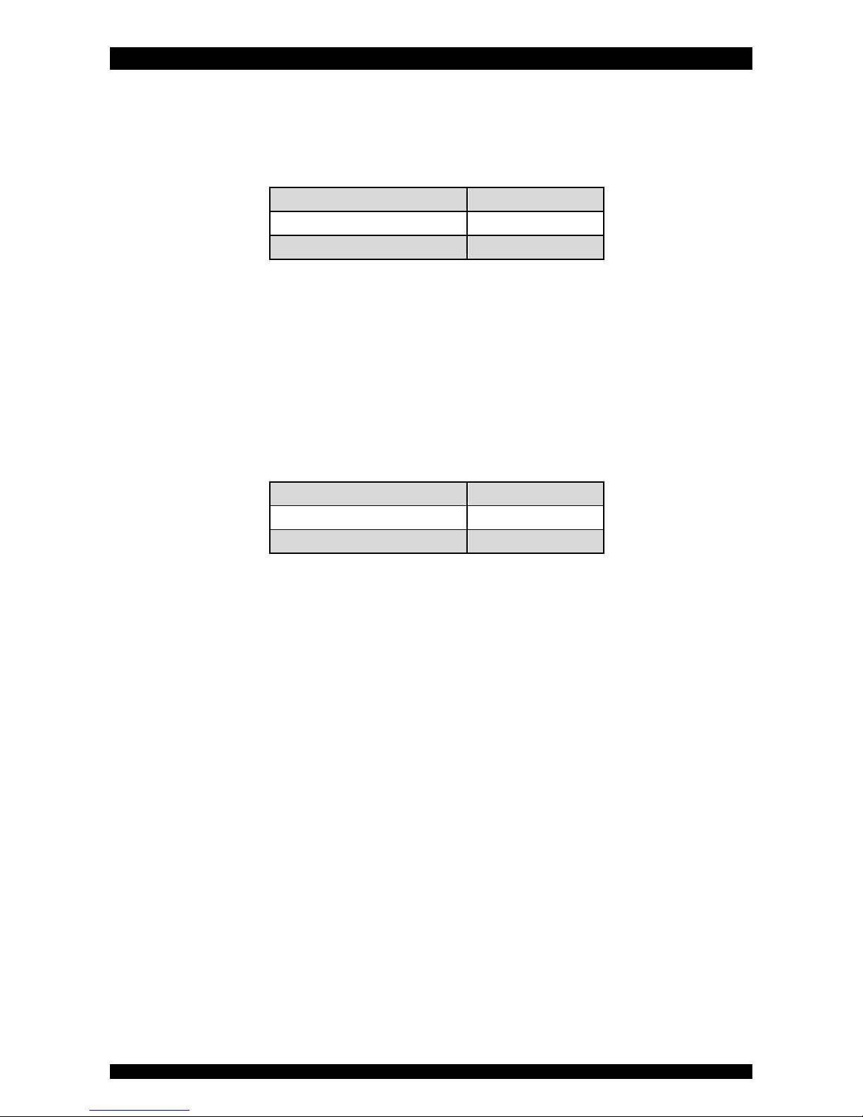
APPLICATION LIMITATIONS PF-OXY:
pH: for Iron removal: 6,8 - 9,0
for Manganese removal: 8,0 - 9,0
for Iron & Manganese removal: 8,0 - 8,5
maximum contaminant content:
Iron (Fe2+) 15 mg/L
Manganese (Mn2+) 2 mg/L
Hydrogen Sulfide (H2S) 5 mg/L
organic matter: max. 4,0 mg/L; higher level may hinder the correct operation of
the system.
chlorine: max. 1,0 mg/L
iron bacteria: if iron bacteria are present, frequent service may be necessary,
while the life of the system may be limited; by properly controlling the iron
bacteria with chlorine or another approved method of bacterial reduction, the
system will function properly.
APPLICATION LIMITATIONS PF-OXY
+
:
pH: 5,8 - 10,5
maximum contaminant content:
Iron (Fe2+) 70 mg/L
Manganese (Mn2+) 35 mg/L
Hydrogen Sulfide (H2S) 15 mg/L
organic matter: water should be free from organic matter.
iron bacteria: if iron bacteria are present, frequent service may be necessary,
while the life of the system may be limited; by properly controlling the iron
bacteria with chlorine or another approved method of bacterial reduction, the
system will function properly.
OPERATING PRESSURE MIN-MAX: 2,5-8,0 bar / 36-116 psi
low operating pressure may lead to insufficient backwash of the filter media,
resulting in an increase in pressure drop and/or a reduction of the filtration
capacity during the service cycle.
if installed on a well, verify that the well pump is powerful enough to provide
sufficient flow rate for the backwash cycle.
check water pressure regularly.
take into account that night time water pressure may be considerably higher than
day time water pressure.
install a pressure reducer ahead of the appliance if necessary.
OPERATING TEMPERATURE MIN-MAX: 4-48 °C / 39-120 °F
do not install the appliance in an environment where high ambient temperatures
(e.g. unvented boiler house) or freezing temperatures can occur.
the appliance cannot be exposed to outdoor elements, such as direct sunlight or
atmospheric precipitation.
do not install the appliance too close to a water heater; keep at least 3 m (10 ft)
of piping between the outlet of the appliance and the inlet of the water heater;

OPERATING CONDITIONS & REQUIREMENTS
Page 5
water heaters can sometimes transmit heat back down the cold pipe into the
appliance; always install a check valve at the outlet of the appliance.
ELECTRICAL CONNECTION:
this appliance only works on 24 VAC; always use it in combination with the
supplied transformer.
in case of damage to the power supply cable of the transformer, immediately
disconnect the transformer from the power outlet and replace the transformer.
make sure to plug the transformer into a power outlet, which is installed in a dry
location, with the proper rating and over-current protection.

ASSEMBLY
Page 6
CONTENT CHECK
Actual parts that you have received, may differ from the
pictures/illustrations in these Instructions!
Only on systems with ≥3 cuft of filter media: for ease of
transportation and installation, the filter media is NOT
loaded in the pressure tank, but delivered in separate bags
of 1 cuft; it must be loaded on-site, after positioning of the
pressure tank.
Check the content of the system, using the Composition
Overview in these Instructions. Identify and lay-out the
different components to facilitate the assembly.
SIMPLEX
Picture 1.a, 2.a, 3.a
A Simplex system consists of 1 single filter module (pressure
tank, filter media, control valve).
During normal operation, the system delivers treated water.
As soon as it initiates a regeneration, it automatically goes
into bypass, guaranteeing uninterrupted supply of untreated
water.
It is possible to install a so called Normally Open Service Valve
(e.g. a solenoid operated diaphragm valve) in the outlet of the
system, that is controlled by the electronic timer of the
system; this Service Valve will be activated during the entire
duration of the regeneration, to close-off the control valve's
standard 'untreated water bypass during regeneration'.
MULTIPLEX PARALLEL
Picture 4
A Multiplex PARALLEL system consists of 2 or more Simplex
systems, that:
- are hydraulically installed in parallel;
- are programmed for different times of regeneration;
- may have a so called Normally Open Service Valve (e.g. a
solenoid operated diaphragm valve) in the outlet of each
Simplex system, that is controlled by the electronic timer
of each Simplex system; this Service Valve will be
activated during the entire duration of the regeneration,
to close-off the control valve's standard 'untreated water
bypass during regeneration'.
During normal operation, all Simplex systems are in service,
doubling/tripling/… the service flow rate!
In case of a power failure, all Service Valves will be
deactivated, meaning the outlet of all Simplex systems will be
open, guaranteeing uninterrupted supply of water.
FILTER MEDIA LOADING
1. Move the pressure tank to the correct installation
location; position it on a flat and level surface. Make sure
to leave enough space for ease of service.
2. Position the riser assembly upright and centred in the
pressure tank; plug the top of the riser tube with a piece
of tape or clean rag, to prevent filter media from entering
the tube.
3. Place a funnel on the pressure tank opening and fill the
pressure tank with filter media; make sure the riser
assembly remains centered in the pressure tank.
4. Rinse the pressure tank opening to remove any grains of
filter media from the threaded section.
5. Unplug the top of the riser tube.
CONTROL VALVE
only for PF-OXY1 & PF-OXY+1
1. Make sure the O-ring in the riser insert and the tank Oring (around the threaded section of the control valve) are
in the correct position.
2. Screw the top distributor onto the control valve.
3. Lubricate the threaded section of the pressure tank, the
top of the riser tube and the tank O-ring of the control
valve; use a silicon-based lubricant.
4. Lower the control valve straight down onto the riser tube,
until the riser tube is correctly inserted in the riser insert;
then push it down firmly and screw it onto the pressure
tank.
only for PF-OXY1,5 & PF-OXY+1,5
Picture 5
1. On the brass valve seat:
make sure the O-ring in the riser insert is in the correct
position;
install the top distributor and fix it by means of the 2
stainless steel screws;
install the tank O-ring in the groove on the flange
around the threaded section.
2. Lubricate the threaded section of the pressure tank, the
top of the riser tube and the tank O-ring of the valve seat;
use a silicon-based lubricant.
3. Lower the valve seat straight down onto the riser tube,
until the riser tube is correctly inserted in the riser insert
inside the valve seat; then push it down firmly and screw
it onto the pressure tank.
4. Install the valve seat O-ring in the groove on the valve
seat.
5. Install the control valve onto the valve seat; mind the
alignment pin!
6. Bolt the control valve to the valve seat by means of the 4
stainless steel bolts; tighten firmly.

ASSEMBLY
Page 7
AIR INJECTION SYSTEM
only for PF-OXY1 & PF-OXY+1
Picture 6.a
Make sure the air injection system is installed in vertical
position, with the check valve and air intake filter screen
pointing upwards. Rotate it to this position if necessary.
only for PF-OXY1,5 & PF-OXY+1,5
Picture 6.b
1. Install the air injection system on the control valve;
tighten the nut firmly by hand.

INSTALLATION
Page 8
INLET & OUTLET
We strongly recommend the use of flexible hoses to
connect the appliance to the water distribution system; use
hoses with a large diameter in order to limit the pressure
loss.
We strongly recommend the installation of a bypass
system (not included with this product!) to isolate the
appliance from the water distribution system in case of
repairs. It allows to turn off the water to the appliance, while
maintaining full-flow (untreated) water supply to the user.
To prevent air from escaping from the compressed air
chamber, make sure the inlet line runs vertically upwards
into the water filter. If this is not possible, install a check
valve in the inlet line.
only for PF-OXY1 & PF-OXY+1:
with factory bypass (optional)
Picture 1
= mains water supply (untreated water)
= inlet of control valve (untreated water)
= outlet of control valve (treated water)
= application (treated water)
1. Screw the factory bypass onto the in/out ports on the
control valve (&); make sure to install the gasket
seals. Tighten the nuts firmly by hand.
2. Screw the connection kit with nuts onto the factory
bypass (&); make sure to install the gasket seals.
Tighten the nuts firmly by hand.
3. Connect the mains water supply to the adaptor on the
inlet port of the factory bypass ().
4. Connect the application to the adaptor on the outlet port
of the factory bypass ().
only for PF-OXY1 & PF-OXY+1:
with 3-valve connection kit (not included)
Picture 2
= inlet of control valve (untreated water)
= outlet of control valve (treated water)
1. Install the 3-valve connection kit.
2. Screw the connection kit with nuts onto the in/out ports
on the control valve (&); make sure to install the
gasket seals. Tighten the nuts firmly by hand.
3. Connect the IN valve of the 3-valve connection kit to the
adaptor on the in port of the control valve ().
4. Connect the OUT valve of the 3-valve connection kit to the
adaptor on the out port of the control valve ().
5. Connect the mains water supply to the inlet of the 3-valve
connection kit.
6. Connect the application to the outlet of the 3-valve
connection kit.
only for PF-OXY1,5 & PF-OXY+1,5:
with 3-valve connection kit (not incl.)
Picture 3
= inlet of control valve (untreated water)
= outlet of control valve (treated water)
1. Install the 3-valve connection kit.
2. Insert the adaptors in the in/out ports on the control valve
(&); make sure not to damage the O-rings. Install the
nuts and tighten them firmly by hand.
3. Connect the IN valve of the 3-valve connection kit to the
adaptor on the in port of the control valve ().
4. Connect the OUT valve of the 3-valve connection kit to the
adaptor on the out port of the control valve ().
5. Connect the mains water supply to the inlet of the 3-valve
connection kit.
6. Connect the application to the outlet of the 3-valve
connection kit.
DRAIN
We recommend the use of a stand pipe with air trap.
To prevent backflow from the sewerage system into the
appliance, always install and use an air gap (included with
PF-OXY1 & PF-OXY1+), to connect the drain hose to the
sewerage system.
Lay-out the drain hose in such a way that pressure loss
is minimized; avoid kinks and unnecessary elevations.
Make sure that the sewerage system is suitable for the
rinse water flow rate of the appliance.
only for PF-OXY1 & PF-OXY+1
Picture 7
1. Install the air gap to the sewerage system; it fits over a
32 mm pipe or inside a 40 mm pipe adaptor. Ensure a
permanent and watertight connection.
2. Connect a 13 mm hose to the drain connection of the
control valve (); secure it by means of a clamp.
3. Run the drain hose to the air gap and connect it to one of
the hose barbs; secure it by means of a clamp. This drain
line operates under pressure, so it may be installed higher
than the appliance.
only for PF-OXY1,5 & PF-OXY+1,5:
Picture 8
1. Connect a pipe to the 1” BSP Male drain connection of the
control valve (); use an appropriate sealant.
2. Run the pipe to the sewerage system and connect it,
ensuring sufficient air gap between the end of the pipe
and the sewerage system. This drain line operates under
pressure, so it may be installed higher than the appliance.
SERVICE VALVE (optional)
Picture 9
1. Plug the DIN plug on the connection cable of the Service
Valve into the DIN socket at the back of the electronic
timer head of the control valve ().

COMMISSIONING
Page 9
ELECTRICAL
1. Connect the appliances power cord to the transformers
output.
2. Plug the transformer into an electrical outlet.
PRESSURIZING
1. Put the bypass system in 'bypass' position.
2. Make sure the electronic controller of the appliance is in
service mode.
3. Open the mains water supply.
4. Open a cold treated water faucet nearby the appliance
and let the water run for a few minutes until all air is
purged and all foreign material that may have resulted
from the installation is washed out; close the faucet.
5. Gently pressurize the appliance, by putting it into service:
close the 'BYPASS' valve;
open the 'OUT' valve;
slowly open the 'IN' valve.
6. After 2-3 minutes, open a cold treated water faucet
nearby the appliance and let the water run for a few
minutes until all air is purged from the installation and the
filter media is rinsed (it is normal for the rinse water to
show some discoloration!); let the water run until the
rinse water is clear; close the faucet.
7. Check the appliance and all hydraulic connections for
leaks.
During the passage through the compressed air
chamber, the treated water will get highly oxygenated. As a
consequence it may become slightly non-transparent (milky
appearance) when it flows from the tap into a glass. This is
totally harmless for the quality of the treated water and will
disappear rapidly if the water is left standing for a moment!
ELECTRONIC CONTROL PANEL
1. Program the electronic controller.
INITIATE A REGENERATION
We strongly recommend to postpone the execution of
this 'start-up' regeneration by 24 hours. The filter media
needs sufficient time to absorb water and reach its normal
service weight. If the regeneration is performed too soon,
the filter media may be pushed against the top distributor
during the backwash cycle, possibly resulting in loss of filter
media or damage to the top distributor.
1. Manually initiate a regeneration, by pressing the scroll
button repeatedly until the display shows:
2. Leave the appliance in this position; the count-down
timer will count down to 0 sec and start a regeneration.
Regen in 10 sec
ELECTRONIC CONTROL PANEL
Page 10
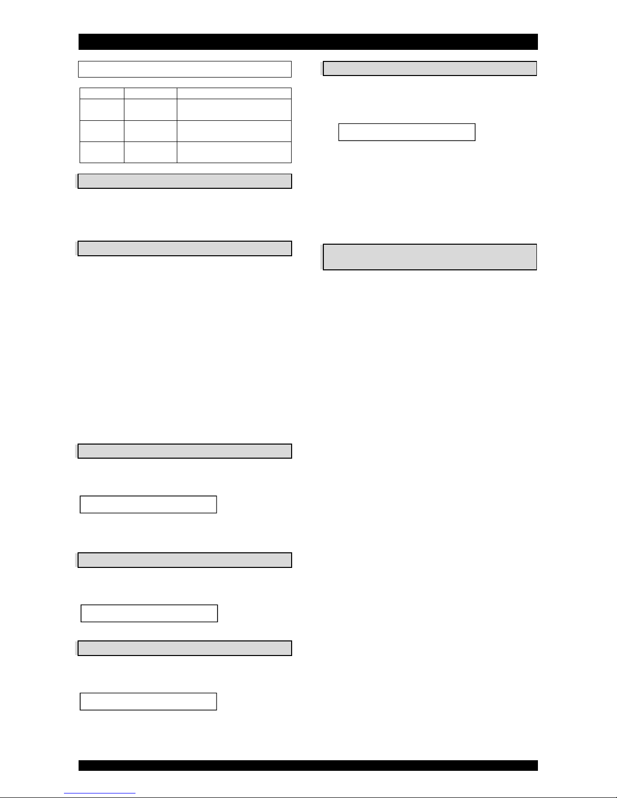
Picture 10
symbol
button
function
SCROLL
to advance to the next
parameter
UP
to increase the value of the
parameter
DOWN
to decrease the value of the
parameter
POWER-UP
After power-up the display will show the installed software
version. After 5 seconds it will automatically revert back to
the service display.
POWER FAILURE
In the event of a power failure, the program will remain
stored in the NOVRAM® during an undefined period, while an
incorporated SuperCap will maintain the correct time of day
during a period of several hours; consequently, in case of
prolonged power failure, the time of day might not be
maintained; if this happens, the time of day will be reset to
8:00 when the power supply is re-established, while the
indication will flash, indicating that the time of day needs to
be set.
When the power failure occurs during the execution of an
automatic regeneration, the control valve will remain in its
last position; when the power supply is re-established, the
control valve will return to the service position, stay there for
60 sec. and restart a complete regeneration from the
beginning.
TIMER FAILURE
In the event of a timer failure, the display will show the
message:
If powering off/on the appliance doesn’t solve this problem,
professional service is required.
SERVICE MODE
In service mode the display shows the time of day and the
number of days remaining until the next regeneration:
REGENERATION MODE
In regeneration mode the display shows the remaining
regeneration time and the remaining cycle time:
The control valve can be reset to service mode at any time by
pressing the scroll button, as such manually advancing it
through the regeneration cycles.
MANUAL REGENERATION
It is possible to manually initiate a regeneration.
1. Press the scroll button repeatedly until the display
shows:
If the control valve is left in this position, the count-
down timer will count down to 0 sec and start a
regeneration.
To cancel this mode, press the scroll button before
the countdown timer has reached 0 sec; the control
valve will return to the service mode.
2. Press the scroll button again if you want to manually
advance the control valve to the next regeneration cycle.
DRIVE MOTOR SPEED
(only for PF-OXY1 & PF-OXY+1)
The drive motor of the control valve, that drives the valve
body to its different regeneration positions, will start-up at
low speed to reduce its noise level. To increase the speed of
the drive motor, simply press the scroll button as soon as
the drive motor is activated.
Service Required
Regen in 10 sec
8:01 4 DAY REM
Rgn:123 CycY:456

ELECTRONIC CONTROL PANEL
Page 11
PROGRAMMING INSTRUCTIONS -
BASIC SETTINGS
Before entering the programming mode, make sure that
the appliance is in the service mode.
1. Press the scroll button; the display will show:
Press the up or down button to set the
language.
2. Press the scroll button again; the display will show:
Press the up button or down button to set the
time of day.
3. Press the scroll button again; the display will show:
Press the up or down button to set the number
of days between regenerations.
The filtration capacity of the appliance mainly depends
on the daily water usage and the Iron/Manganese content
in the water; many other factors may also have a significant
impact on the filtration capacity. Therefore it is
recommended to regenerate the appliance on a regular time
basis. In most applications a regeneration every 4 days
should be sufficient.
In case of extreme iron/manganese content and/or
water consumption, it is recommended to lower the
regeneration interval to 1 or max. 2 days.
Language:English
Set time: 8:01
Interval:4 Days
 Loading...