

Page 1
These instructions contain important information which will help you get best from your
equipment and ensure safe and correct assembly, use and maintenance.
If you need help or have damaged or missing parts, call the Customer Helpline: 0345 600 1714
or visit www.argos-support.co.uk
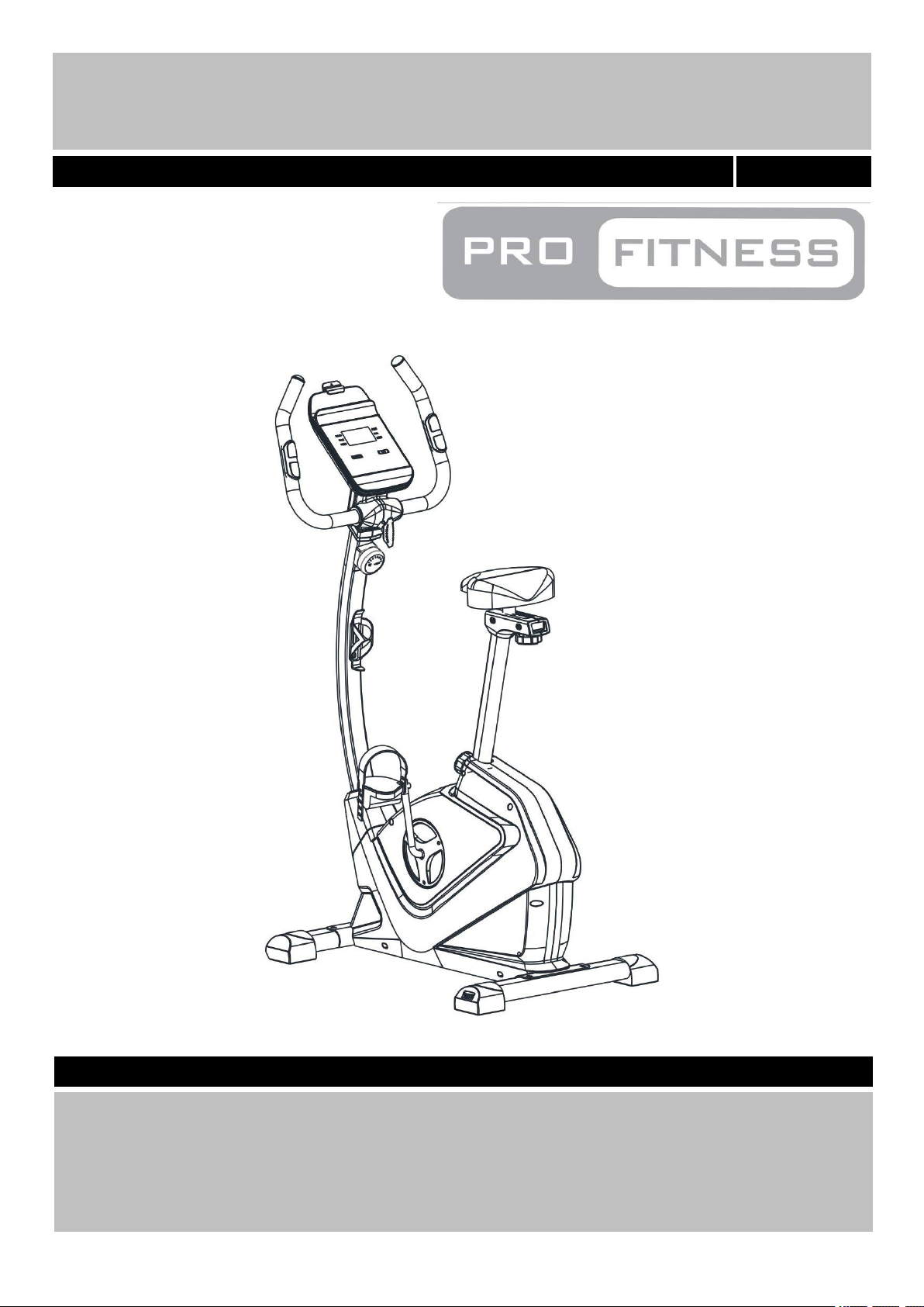
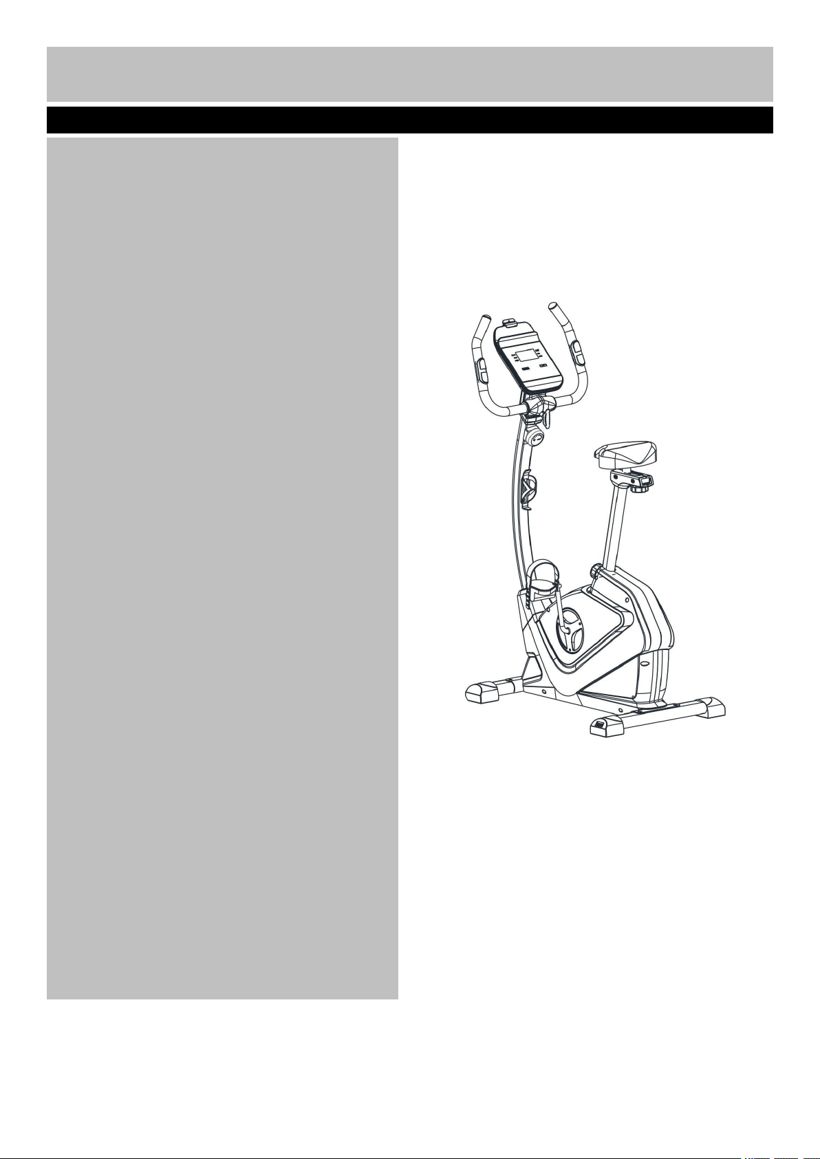
EB1000 Exercise Bike
Assembly & User’s Instructions- Please Keep for future reference
888/3559
Important – Please read these instructions fully before assembly or use
Page 2
Contents
Safety Information
2-3
Components - Parts
4
Components – Fixings
5
Assembly Instructions
6-13
Workout Area
14
Exercise Information
15-21
* Before starting
15
* Muscle Chart
16
* Warming up and Cooling down
17-18
* Console Operations
19-20
*Adjustment of the seat
21
*Adjustment of the handle
21
Care and Maintenance
22
Exploded Parts Diagram
23
Parts List
24-25
1
Page 3
、
This exercise equipment is built for optimum safety. However, certain precautions apply whenever you
Assembly
• The product must be installed on a stable and
level surface. To protect the floor or carpet from
damage, place a mat under the exercise bike.
• Assemble the item as close to its final position
(in the same room) as possible.
• Make sure you have enough space to layout the
parts before starting.
• Keep children and animals away from the work
area, small parts could pose a choking hazard if
swallowed.
• Dispose of all packaging carefully and responsibly.
• Check you have all the components and tools
listed in the parts list, bearing in mind that, for ease
of assembly, some components are pre-assembled.
• The assembly of this equipment is best carried out
by 2 people.
Use
• It is the responsibility of the owner to ensure that
all users of this product are properly informed as to
how to use this product safely.
• This product is intended for domestic use only.
Do not use in any commercial, rental, or institutional
setting.
• Use the equipment only for intended use, as
described in this manual. Do not use attachments
not recommended by the manufacturer.
• Keep this equipment indoors, away from moisture
and dust. Do not put the equipment in a garage,
outbuilding, covered patio, or near water.
• Your product is intended for use in clean dry
conditions. You should avoid storage in excessively
cold or damp places as this may lead to corrosion
and other related problems that are outside our
control.
• Keep unsupervised children away from the
equipment.
• Disabled persons should not use the equipment
without a qualified person or doctor in attendance.
• Always wear appropriate workout clothing when
exercising. Do not wear loose or baggy clothing, as
it may get caught in the equipment. Wear trainers to
protect your feet while exercising.
• Do not place any sharp objects around the
equipment.
• Keep hands away from all moving parts.
• If any of the adjustment devices are left projecting,
they could interfere with the user’s movement.
• Before using the equipment to exercise, always
perform stretching exercises to properly warm up.
• Only one person at a time should use the
equipment.
• If the user experiences dizziness, nausea, chest
pain, or other abnormal symptoms stop the workout
and seek immediate medical attention.
• Injuries to health may result from incorrect or
excessive training.
• This product is suitable for a maximum user
weight of: 120kg.
• This product conforms to: BS EN ISO 20957-1
and -5 Class (H) - Home Use - Class (C).
• This stationary training equipment is not suitable
for high accuracy purposes.
• The braking system is adjustable.
• Always examine your exercise bike before use to
ensure all parts are in working order.
• Never insert any object or body parts into any
opening.
• Warning: Batteries are to be inserted with the
correct polarity. Incorrect installation of batteries may
cause battery leakage and corrosion, resulting in
damage to the computer.
• Do not mix old and new batteries, or
batteries of different types.
Important – Please read fully before assembly or use
Safety Information
2
operate a piece of exercise equipment. Be sure to read the entire manual before you assemble, operate or
use this equipment.
Page 4
Warning: Before beginning any exercise program, consult your Doctor. This is
especially important for persons over the age of 35 or persons with pre-existing health problems. You MUST
read all instructions before using any fitness equipment. Argos and its associates assumes no responsibility for
personal injury or property damage sustained by or through the use of this product. Over exercising may result
in serious injury or death. If you feel faint stop exercising immediately. Warning! Heart rate monitoring systems
may be inaccurate. For the most accurate heart rate measure, please hold both hand pulse sensors
continuously during any programme.
• Do not dispose of batteries in a fire.
• Do not dispose of batteries wit
normal household waste, take to a local recycling
centre.
• Non-rechargeable batteries are not to be
recharged.
• Rechargeable batteries are only to be charged
under adult supervision.
• Rechargeable batteries are to be removed from
the product before being charged.
• Exhausted batteries are to be removed from the
product.
• Supply terminals are not to be short-circuited
3
Safety Information
Important –
Please read fully before assembly or use
Page 5
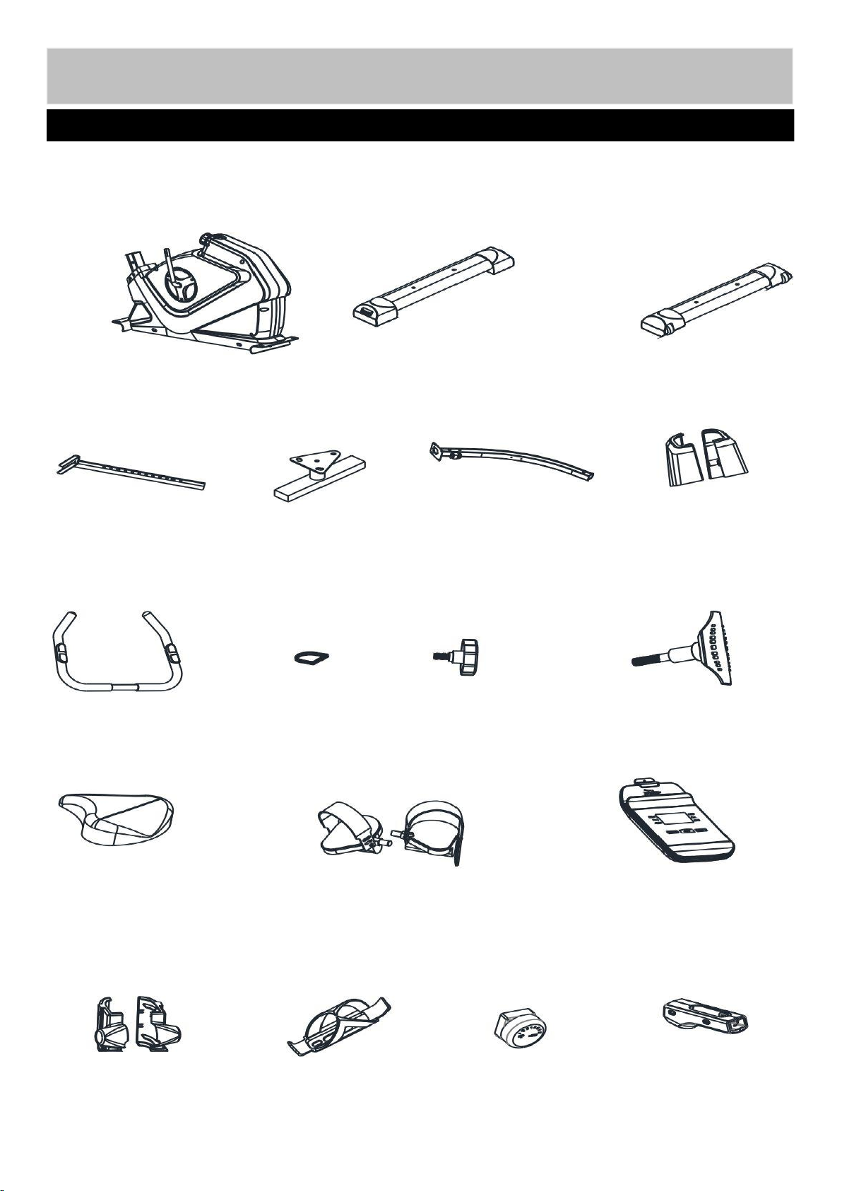
Note: Some of the smaller components may be pre-fitted to larger components. Please check carefully
Components - Parts
If you have damaged or missing parts, please call
the Customer Helpline: 0345 600 1714.
Please check you have all parts listed below
4
1. Main Frame
2. Rear Stabilizer
3. Front Stabilizer
4. Seat Post
5. Seat Bracket
6. Front Post
7. Handle
9. M10 Lock Knob
10. M8 Lock Knob
11. Saddle
12. Pedal (Left/Right)
13. Console
15. Handle Cover (L/R)
16. Bottle Holder
68. Tension knob
38. Saddle Cover(L&R)
33. Front L/R Post Cover
37. Front Post Ring
before contacting Argos regarding any missing components.
Page 6
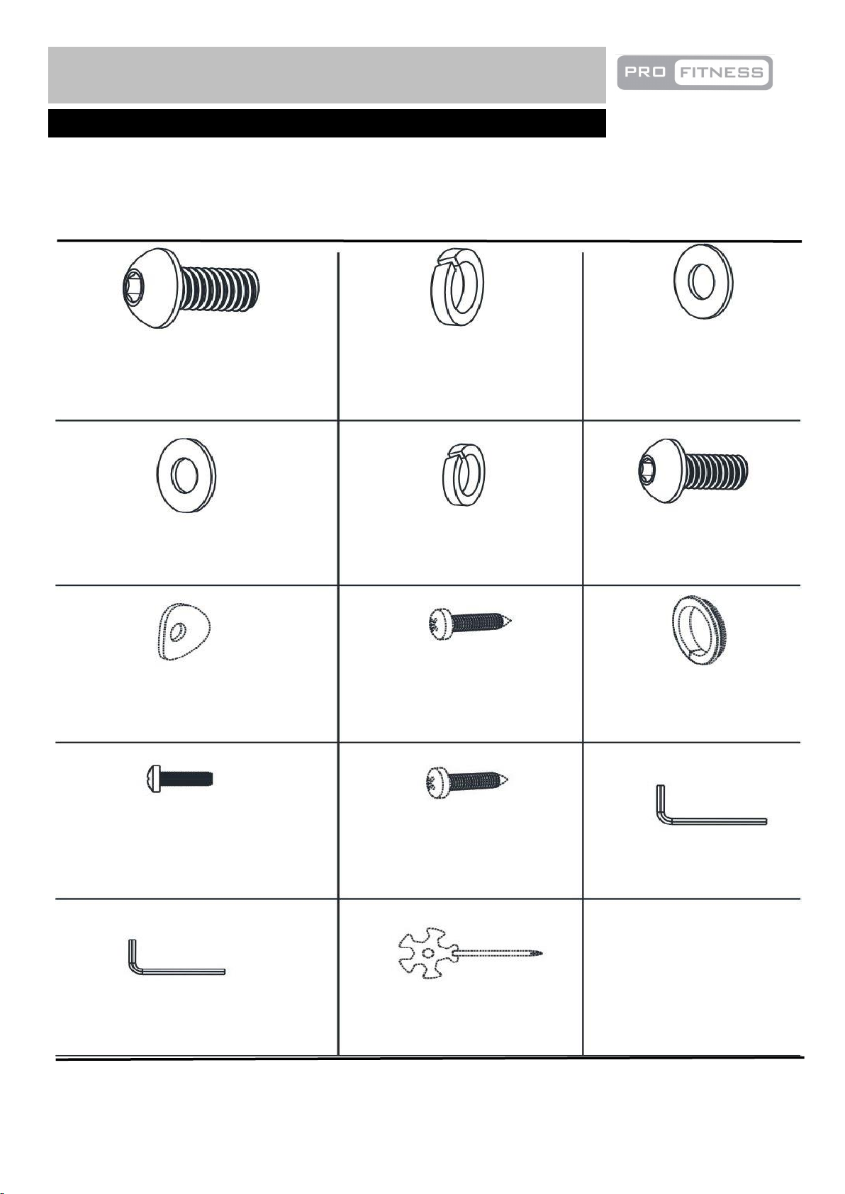
Note: The quantities below are the correct amount to complete the assembly. In some cases more
Components - Fixings
Please check you have all parts listing below
5
M10x20mm Allen Bolt × 4
17
18
19
21
22
23
24
25
74
10mm Spring Washer × 4
10mm Washer × 4
8mm Washer × 2
8mm Spring Washer × 4
M8x15mm Allen Bolt × 4
8mm Arc Washer × 2
ST4.2x15mm Philips Selfdrilling Screw × 2
5mm Allen Key × 1
6mm Allen Key × 1
Multi Wrench × 1
Joint Ring × 2
M5x5mm Philips Bolt × 4
77
ST4.2x15mm Philips Screw × 3
34
hardware may be supplied than are required. Some of the fixings are pre-fitted to the larger components.
Please check carefully before contacting Argos regarding any missing fixings.
Page 7
`
Assembly Instructions
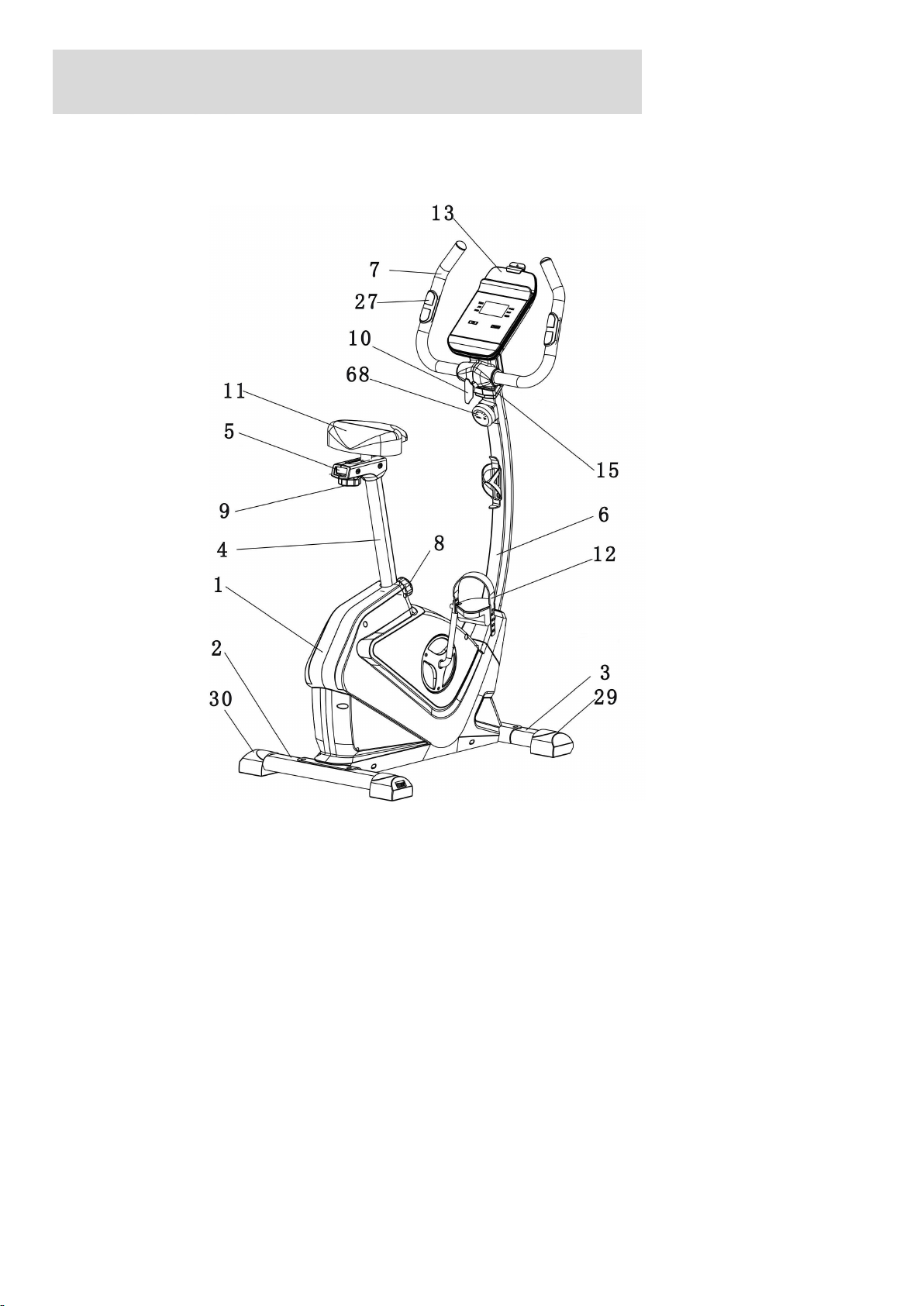
13 console
15 Left & Right Handle Cover
27 Handle Pulse Sensor
29 L&R Transport Wheel
30 Level Foot
68 Tension Knob
6
Total mass of the product is 25.5 kg. Total size of the equipment is (width) 56cm × (depth) 109cm × (height)
141 cm.
KEY
1 Main Frame
2 Rear stabilizer
3 Front Stabilizer
4 Seat Post
5 Seat Adjustment Bracket
6 Front Post
7 Handle
8 M16 Lock Knob
9 M10 Lock Knob
10 M8 T Shaped Lock Knob
11 Saddle
12 Left & Right Pedal
Page 8
Assembly Instructions
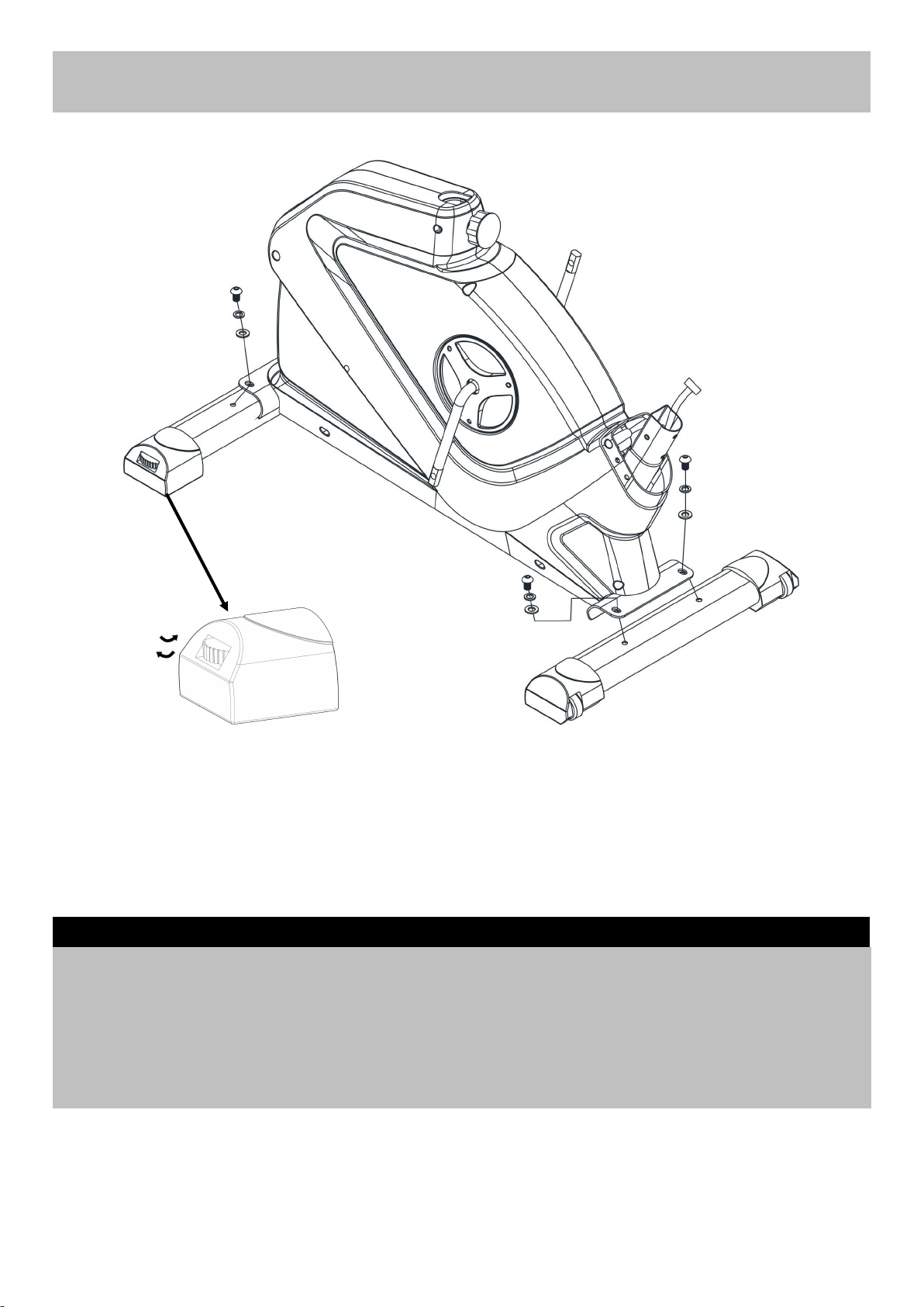
A. Attach Front Stabilizer (3) to Main Frame (1) using 2 x M10x20MM Allen bolts (17), 2 x10MM Spring
Washers (18) and 2 x10MM Washers (19).
B. Attach Rear Stabilizer (2) to Main Frame (1) using 2 x M10x20MM Allen bolts (17), 2 x10MM Spring
Washers (18) and 2 x10MM Washers (19).
Note: The knob on the Levelling Feet (30) can be rotated to ensure the bike sit flat on the ground as
shown in the diagram. Turn it anti clockwise to increase height and turn it clockwise to decrease height.
Step 1
7
2
17
18
19
17
18
19
1
3
30
17
18
19
Page 9
Assembly Instructions
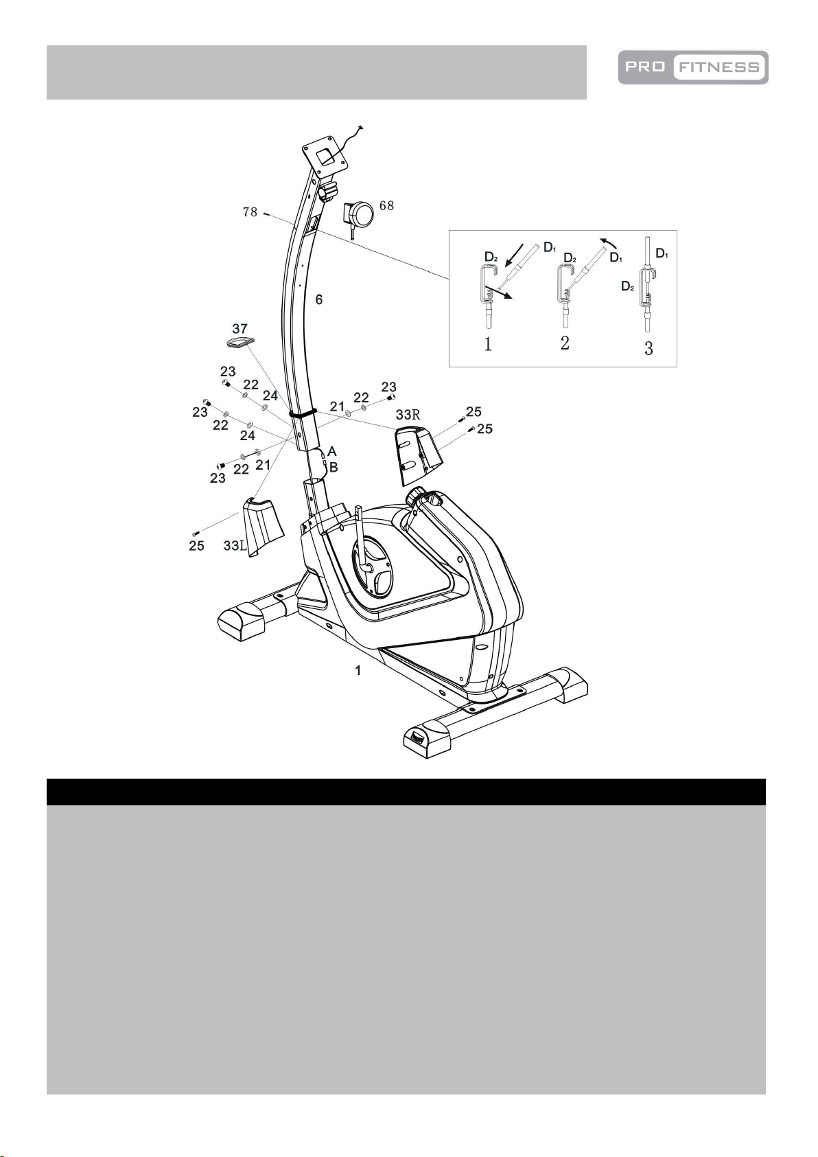
A. Place the Front Post Ring (37) around the Front Post (6).
B. Connect the Main Wire A and B.
C. Fix the Front Post (6) to the Main Frame (1) and tighten with 4 x M8x15MM Allen bolts (23), 4 x
8MM Spring Washers (22), 2 x 8MM Washers (21) and 2 x 8MM Arc Washers (24).
D. Attach the Front Post Cover (33L/R) to the Main Frame (1) and the Front Post Ring (37) with 3 x
ST4.2 x 15mm Phillips Screws (25).
E. Remove the M5x50mm Philips Bolt and Washer (78) from the Tension Knob (68).
Note: The M5x50mm Philips Bolt and Washer (78) is pre-assembled to the Tension Knob (68).
F. Turn the Tension Knob (68) to Level 1 and connect the bottom of the tension knob with the hook as
shown in the diagram. Then attach the Tension Knob (68) to the Front Post (6) using 1 x M5x50mm
Philips Bolt and Washer (78).
Step 2
8
Page 10
Assembly Instructions
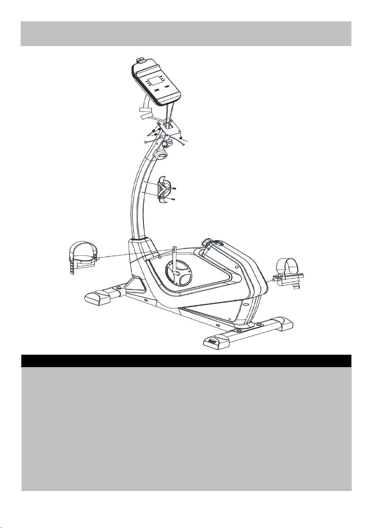
A. Connect the Pedals (12 L&R) to Cranks (41) as shown.
Note: For the two foot pedals marked "L" and "R". Fasten the left pedal by turning anti-clockwise and
fasten the right pedal by turning clockwise. Attach the pedal straps to the pedals as shown in the
diagram, the tension for pedal strap is adjustable.
B. Fix the Bottle Holder (16) to the Front Post (6) with2 x ST4.2 x 15mm Philips Screw (34).
C. Connect the Main Wire C to D, then pass the two Console Pulse Sensor Wires E through the upper
openings of the Front Post (6) as shown in the diagram.
D. Attach the Console(13) onto the top of the Front Post (6) and secure with 4 x 8MM Dome Head
Philips Bolts (71).
Note: The 4 x 8MM Dome Head Philips bolts (71) are pre-fitted on the back of the Console (13).
Step 3
9
12R
12L
63413
16
713471
1CD
E
E
Page 11
Assembly Instructions
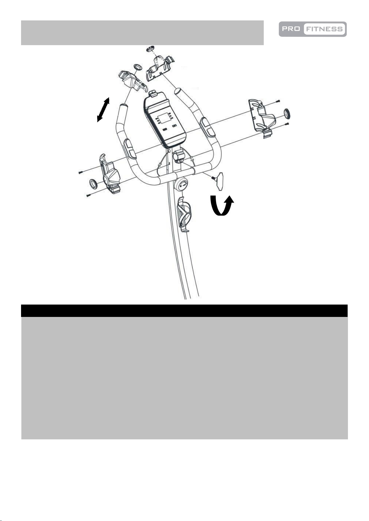
A. Attach the Handle (7) to the bracket on the Front Post (6), and secure with M10 Lock knob (10).
Note: To adjust the position of the handle, turn the lock knob (10) anti clockwise to loose the handle
(7) as shown in the diagram, and adjust the handle (7) to your required position, then secure the lock
knob (10).
B. Connect the two signal Wires(E) from Front Post (6) to the two Wires (F)from Handle (7).
C. Put the Left Handle Cover (15-L) and Right Handle Cover (15-R) on the left and right side of the
Handle (7) respectively, and then lock them to Front Post (6) using 4 x ST4.2x15mm Philips Screw
(25). Please note that the 4 × ST4.2 × 15mm Philips Screw (25) are pre-assembled.
D. Put two Joint Rings (74) on the left and right side of the Handle (7) respectively, then push them to the
Left and Right Handle Cover (15 L & R).
Step 4
10
74
15L
25
25
6
25
25
74
7
10
15R
EEF
F
Page 12
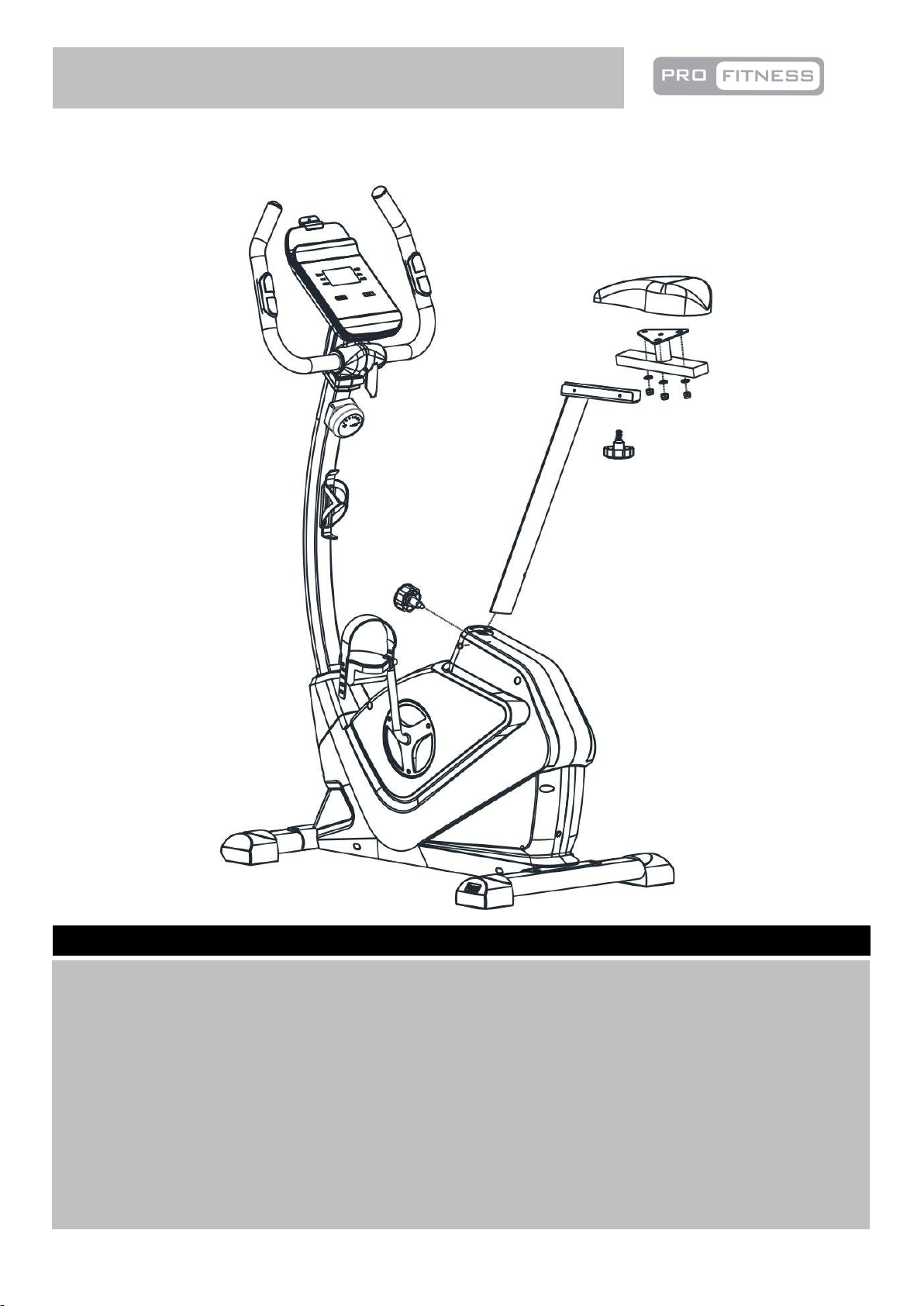
A. Fix the Saddle (11) to the Seat Bracket (5) using 3 x 8MM Washers (21) and 3 x 8MM Aircraft Nuts
(20).
Note: The fixings (20) and (21) have been pre-fitted to the Saddle (11).
B. Attach the Seat bracket (5) to the top of the Seat Post (4) using M10 Lock Knob (9).
Move the Saddle (11) forward or backward to a suitable position then tighten the M10 Lock Knob (9).
C. Insert the Seat Post (4) into the Main frame (1). Position the Seat Post (4) upward and downward at
your required and secure with the M16 Lock knob (8).
Note: The seat height is correct when the knee is slightly angled with the pedal vertically down and the
foot parallel to the floor.
Step 5
11
Assembly Instructions
1
11
21
20
5
4
9
8
Page 13
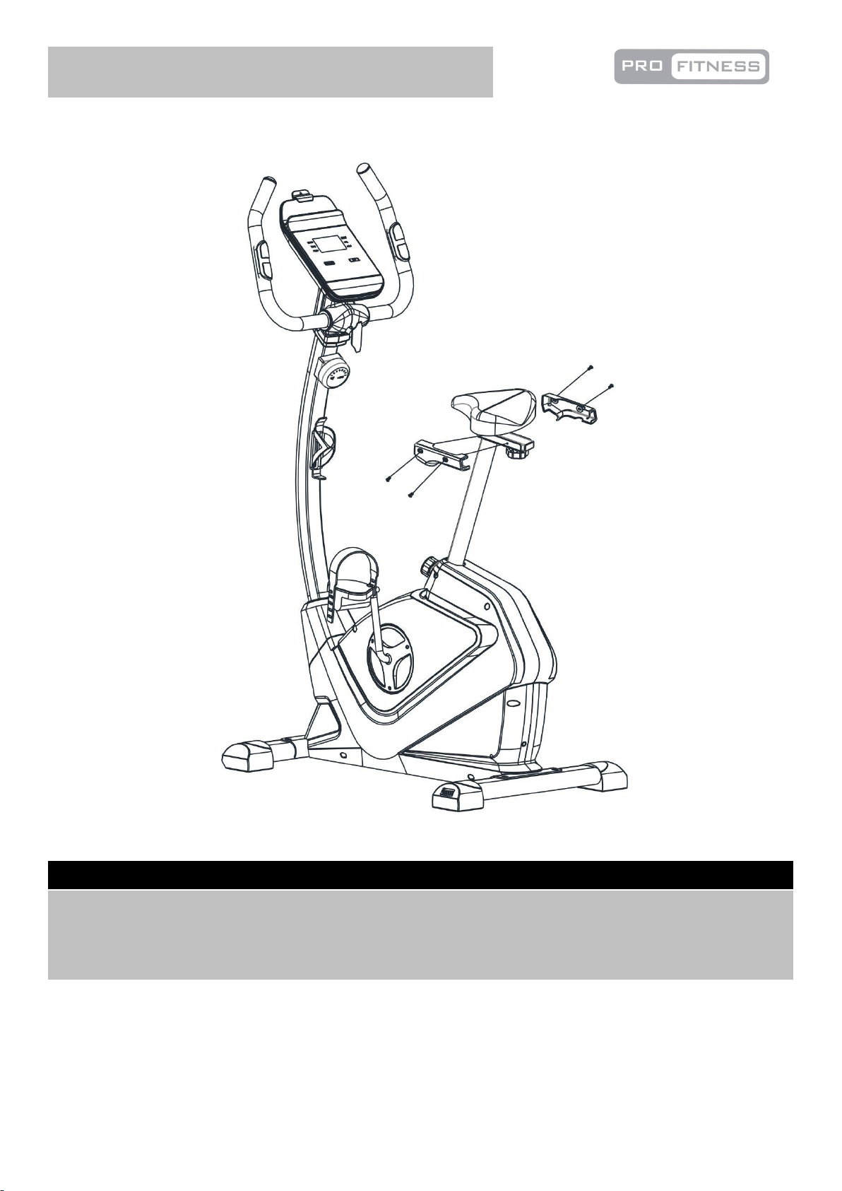
Assembly Instructions
Step 6
A. Fix the Saddle covers (38 L&R) to the Seat adjustable bracket (5),using M5 x 5mm Philips Screw
(77).
77
5
38L
38R
12
77
77
77
Page 14
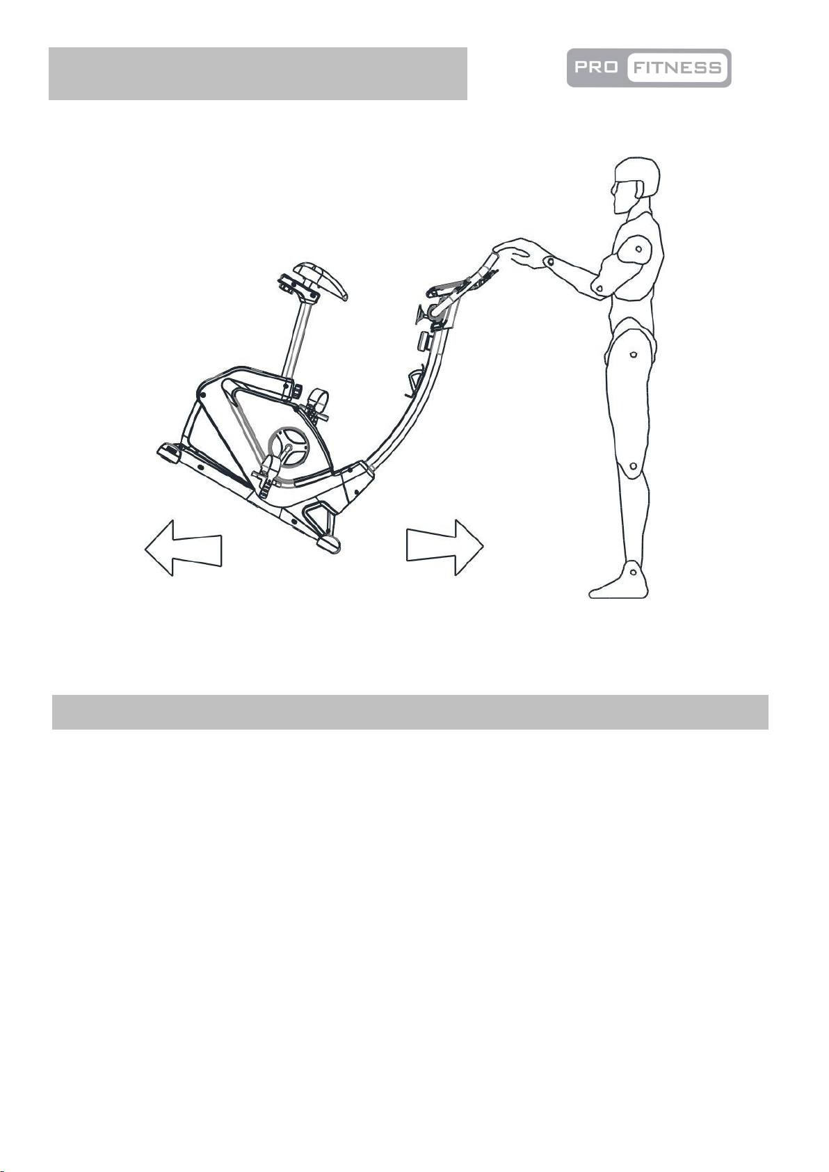
13
Assembly Instructions
Hold the handle to move the bike as shown in the diagram.
Page 15
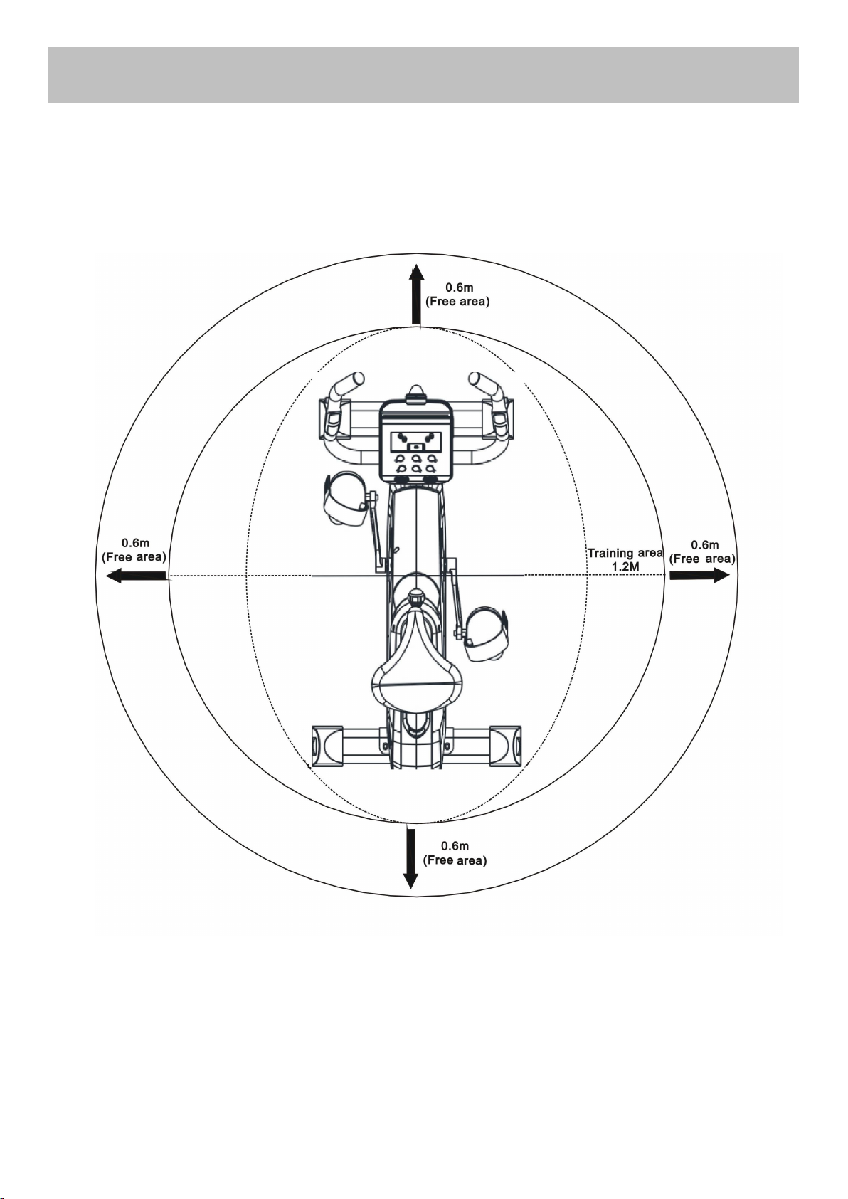
The free area must be at least 0.6m greater than the training area. This is a space where you can safely
Workout area
14
dismount, without obstruction, in case of an emergency. Where two pieces of equipment are positioned
adjacent to each other the free area may be shared.
Only one person should be within the training area when the equipment is in use.
Page 16
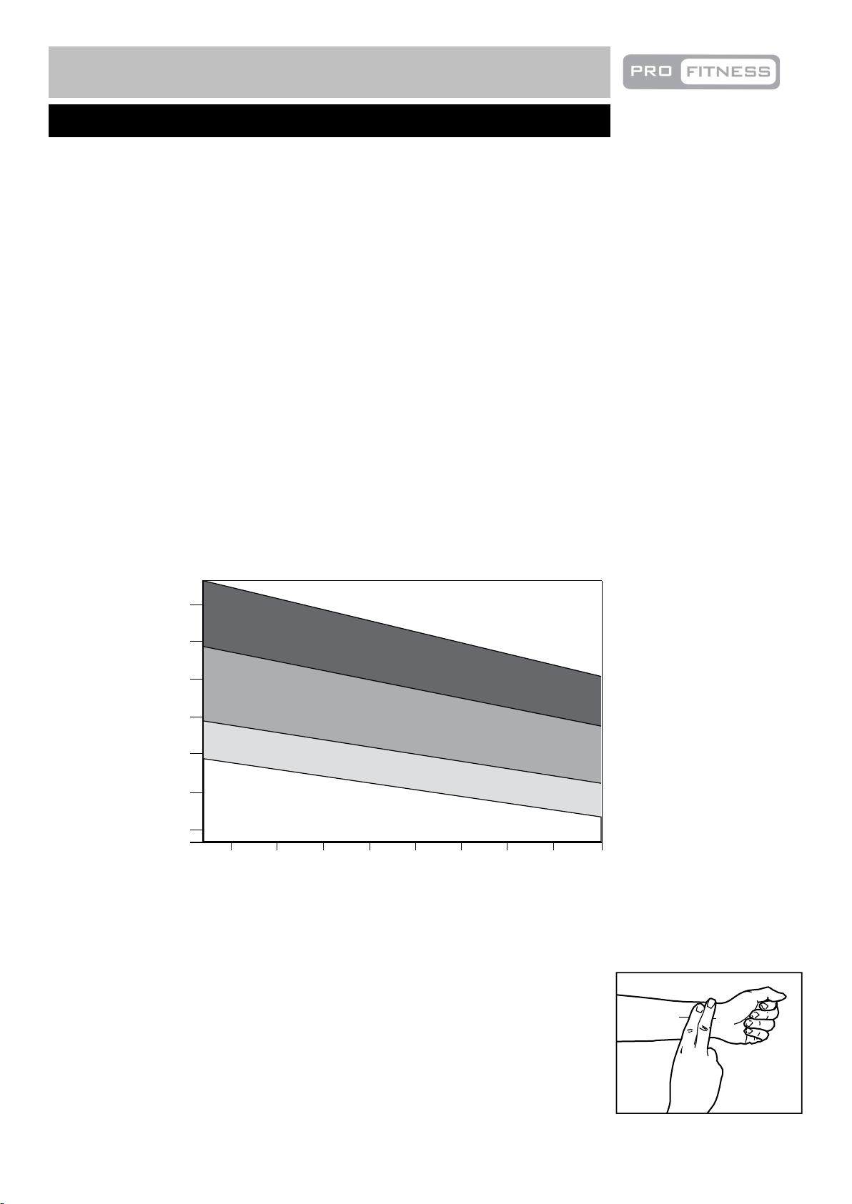
85% to Max
65% to 85%
55% to 65%
Up to 55%
Tailor your exercise program according to your physical condition. If you have been inactive for several
Cardiovascular
performance
Intermediate aerobic
Effective fat burning
Exercise Information
Before starting
15
Beats per minutes (bpm)
years, or are overweight, you must start slowly and increase your time on the equipment; a few minutes per
workout increase is advisable.
Initially, you may be able to exercise only for a few minutes in your target zone, however, your aerobic
fitness will improve over the next six to eight weeks. Don’t be discouraged if it takes longer. It’s important to
work at your own pace.
Please remember these essentials:
• Have your doctor review your training and diet programs to advise you of a workout routine you should
adopt.
• Begin your training program slowly with realistic goals.
• Monitor your pulse frequently. Establish your target heart rate based on your age and condition.
• Set up your equipment on a flat even surface with adequate training area, as prescribed in this manual.
Exercise intensity
To maximize the benefits of exercising, it is important to exercise at an appropriate intensity. The intensity
level can be found by using your heart rate as a guide. For effective aerobic exercise, your heart rate should
be maintained at a level between 65% and 85% of your maximum heart rate as you exercise. This is known
as your target zone. You can find your target zone in the table below.
200
180
160
140
120
100
80
25 30 35 40 45 50 55 60 70
Age
During the first few months of your exercise program, keep your heart rate near the low end of your target zone
as you exercise. After a few months, your heart rate can be increased gradually until it is near the middle of
your target zone as you exercise.
To measure your heart rate, stop exercising but continue moving your legs or
walking around and place two fingers on your wrist. Take a six-second heartbeat
count and multiply the results by 10 to find your heart rate. For example, if your
six-second heartbeat count is 14, your heart rate is 140 beats per minute.
(A six-seconds count is used because your heart rate will drop rapidly when you
stop exercising.) Adjust the intensity of your exercise until your heart rate is at the
required level.
Page 17
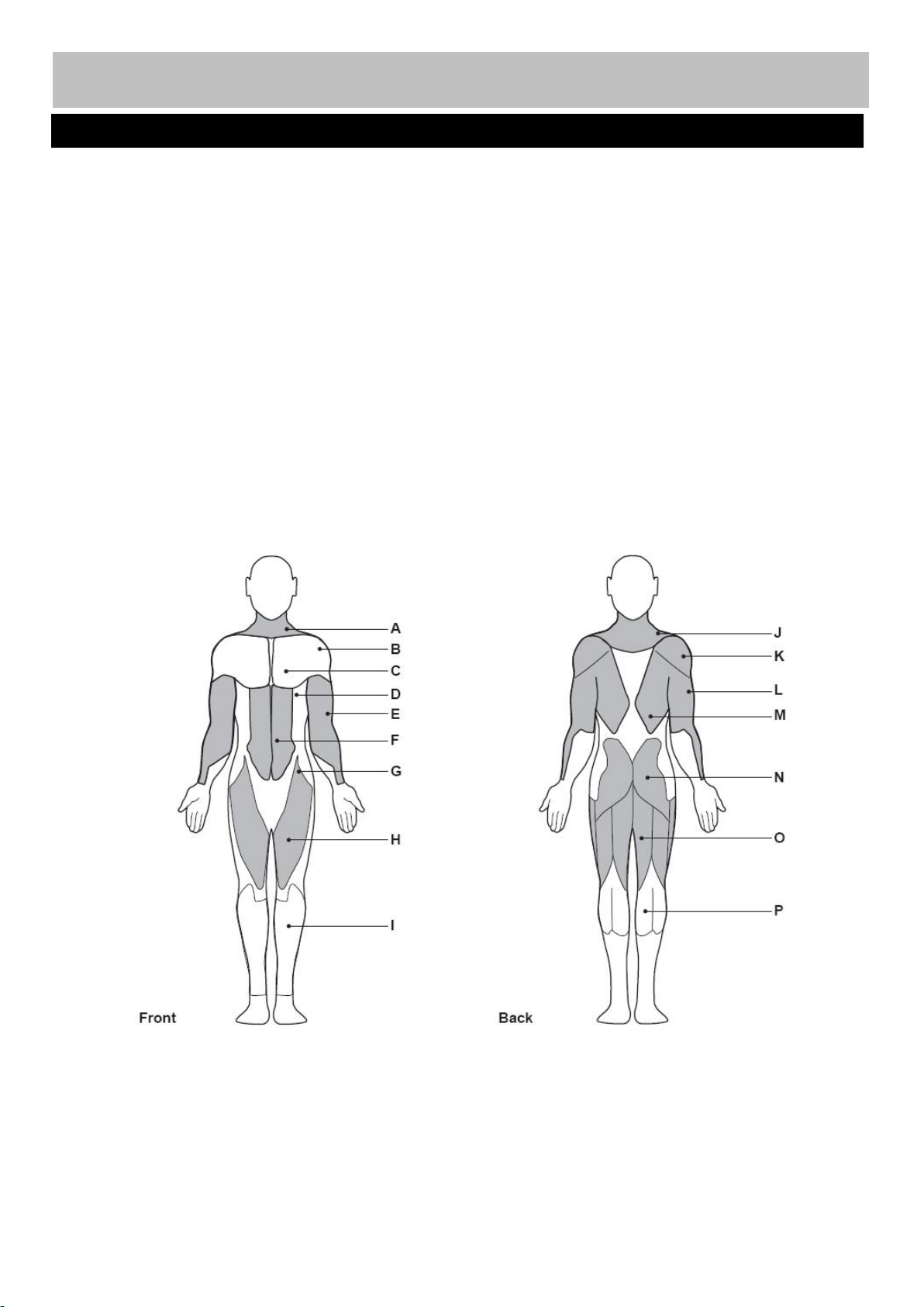
Aerobic Exercise
Muscle Chart
16
Exercise Information
A: Trapezius
B: Anterior Deltoid
C: Pectoralis Major
D: Serratus Anterior
E: Biceps
F: Abdominal
G: Sartorius
H: Quadriceps
I: Tibialis Anterior
J: Trapezius
K: Posterior Deltoid
L: Triceps
M: Latissimus Dorsi
N: Gluteals
O: Hamstrings
P: Gastrocnemiu
Aerobic exercise improves the fitness of your lungs and heart - your body’s most important muscle.
Aerobic exercise is promoted by any activity that uses your large muscles (arms, legs, or buttock, for
example).
Weight Training
Along with aerobic exercising which helps get rid of and keep off the excess fat that our bodies can
store, weight training is an essential part of an exercise routine. Weight training helps tone, build and
strengthen muscle. If you are working above your target zone, you may want to do a lower number of
reps.
Targeted Muscle Groups
The exercise routine that is performed on the exercise bike will develop the lower body muscle groups.
These muscle groups are highlighted on the muscle chart below.
Page 18
Each workout should include the following three parts:
Warming up and Cooling down
17
Exercise Information
leg.
1. A warm-up, consisting of 5 to 10 minutes of stretching and light exercise. A proper warm-up
increases your body temperature, heart rate, and circulation in preparation for exercise.
2. Training zone exercise, consisting of 20 to 30 minutes of exercising with your heart rate in your training
zone. (Note: During the first few weeks of your exercise program, do not keep your heart rate in your
training zone for longer than 20 minutes.)
3. A cool-down, with 5 to 10 minutes of stretching. This will increase the flexibility of your muscles and
will help to reduce post-exercise muscle soreness.
Exercise Frequency
To maintain or improve your condition, plan three workouts each week, with at least one day of rest
between workouts. After a few months of regular exercise, you may complete up to five workouts each
week, if desired. Remember, the key to success is make exercise a regular and enjoyable part of your
everyday life.
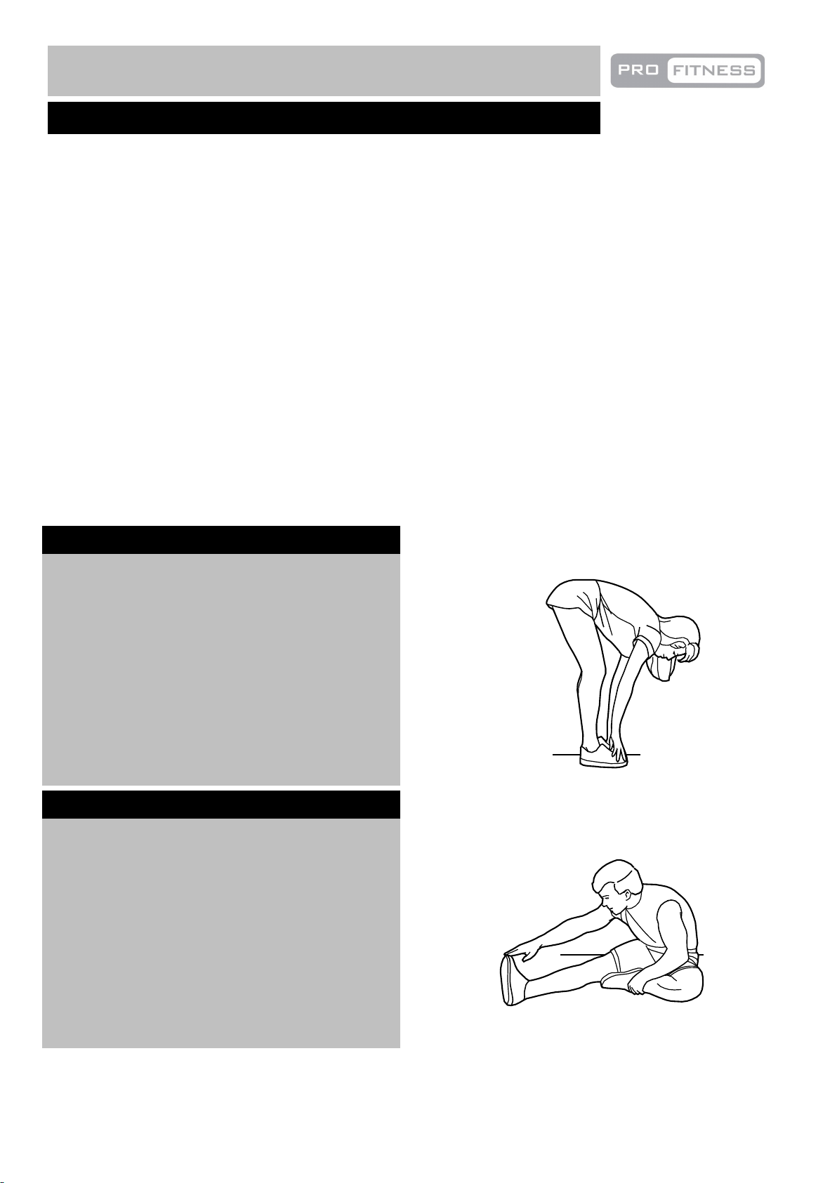
Suggested Stretches
For a correct warm up, see the followingbasic stretching exercises. Move slowlyasyoustretch, neverbounce.
Toe touch stretch
Stand with your knees bent slightly and
slowly bend forward from your hips.
Allow your back and shoulders to relax
as you reach down toward your toes as
far as possible.
Hold for 15 counts, then relax
Repeat 3 times.
Stretches: Hamstrings, back of knees and back.
Hamstring stretch
Sit with one leg extended. Bring the sole
of the opposite foot toward you and rest
it against the inner thigh of your
extended leg. Reach toward your toes
as far as possible.
Hold for 15 counts, then relax
Repeat 3 times for each
Stretches: Hamstrings, lower back and groin.
Page 19
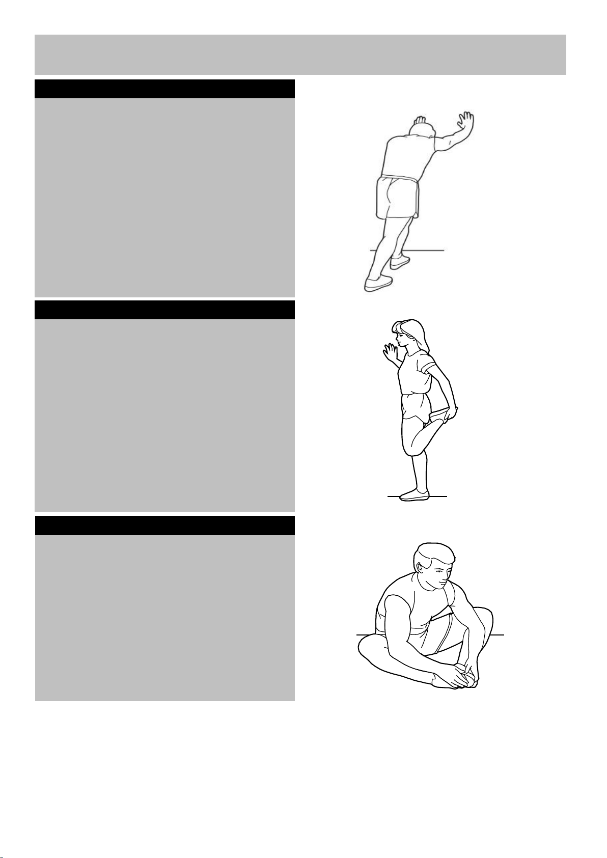
Inner thigh stretch
Calf/achilles stretch
Exercise Information
18
leg.
With one leg in front of the other, reach
forward and place your hands against a wall.
Keep your back leg straight and your back
foot flat on the floor. Bend your front leg,
lean forward and move your hips toward the
wall.
Hold for 15 counts, then relax.
Repeat 3 times for each leg. To cause
further stretching of the achilles
tendons, bend your back leg as well.
Stretches: Calves, achilles tendons and ankles.
Quadriceps stretch
With one hand against the wall for
balance, reach back and grasp one foot
with your other hand. Keeping your bent
knee pointing directly downward towards
the floor, gentle pull your
heel towards your buttock until you feel a gentle
stretch in the target area.
Hold for 15 counts, then relax.
Repeat 3 times .
Stretches: Quadriceps and hip muscles.
Sit with the soles of your feet together
and your knees outward. Pull your feet
toward your groin area as far as possible.
Hold for 15 counts, relax.
Repeat 3 times.
Stretches: Quadriceps and hip muscles.
Page 20
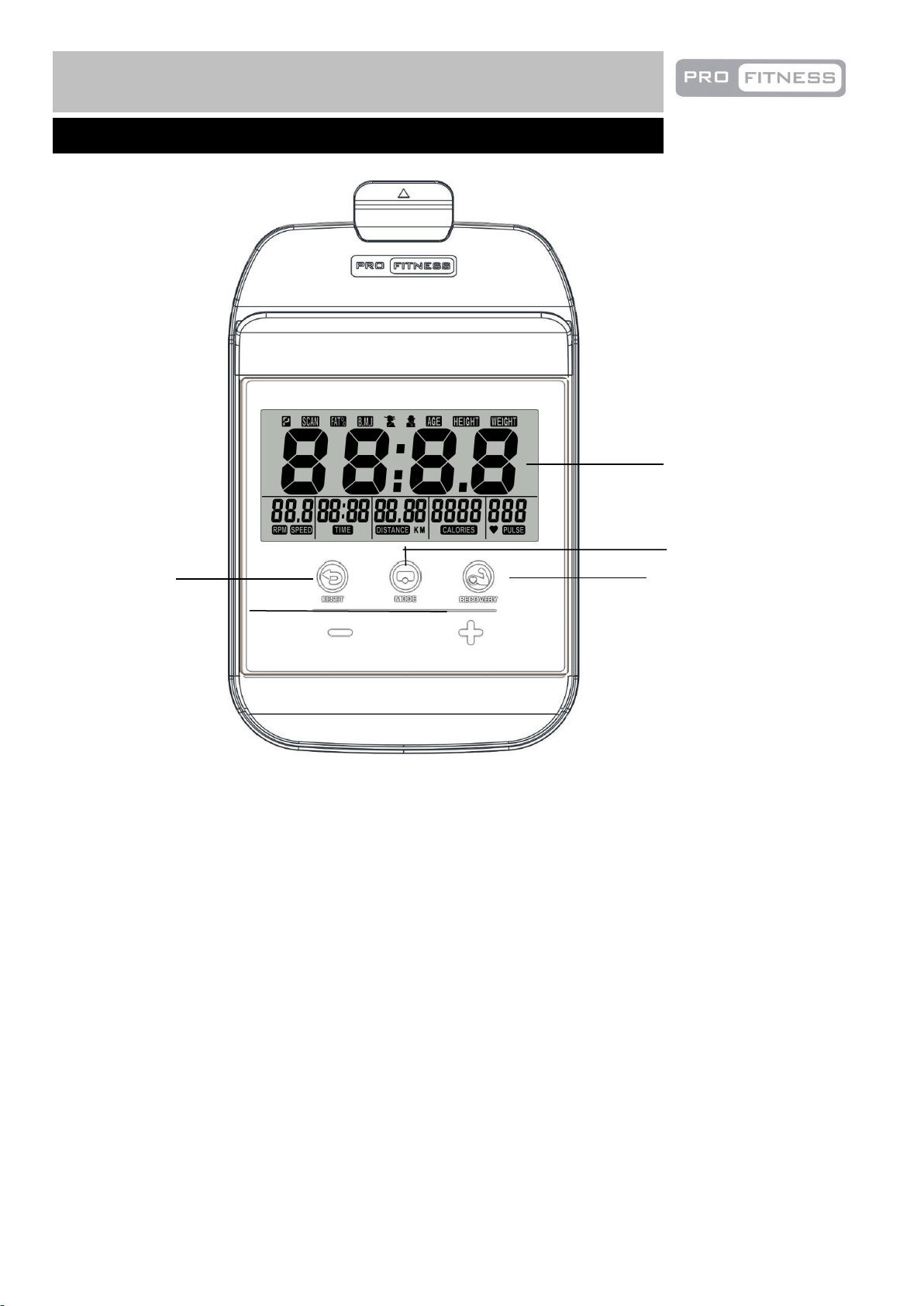
RECOVERY Key:
Exercise Information
Console Operation
19
Display
Mode
Recovery
Reset
The recovery function will test your fitness recovery. To do this, hold the hand pulse sensors for one minute
after which a fitness value will be displayed; F1.0 is excellent fitness and F6.0 is very poor fitness.
MODE: This key lets you select and lock on to a particular function which you want.
Press to Choose SCAN, if you do not want the scan mode, press the Mode key until the pointer is next
to the “flashing” function which you want. The unit can be reset by either changing the battery or
pressing the MODE key for 4 seconds
AUTO ON /OFF:The console will switch on automatically when the exercise bike is in motion. The
console will enter Clock and Temperature mode when the speed has no signal input or no keys are
pressed for approximately 4 minutes.
RESET: Clear the data to zero when set up your workout.
A. SPEED: Workout speed.
B. DISTANCE: Distance traveled.
C. TIME: Workout time.
D. CALORIES: Calories burnt.
E. RPM: display the speed value during exercise, measuring range 0 ~ 999.Out of range shows 999. If
there is no signal input within 4 seconds, the speed will be 0.
F. HR: Heart rate sensors are used to measure the number of beats per minute.Your current heart rate will
be displayed 1 to 2 seconds after the heartbeat signal is received.The heartbeat symbol flashes when
Page 21
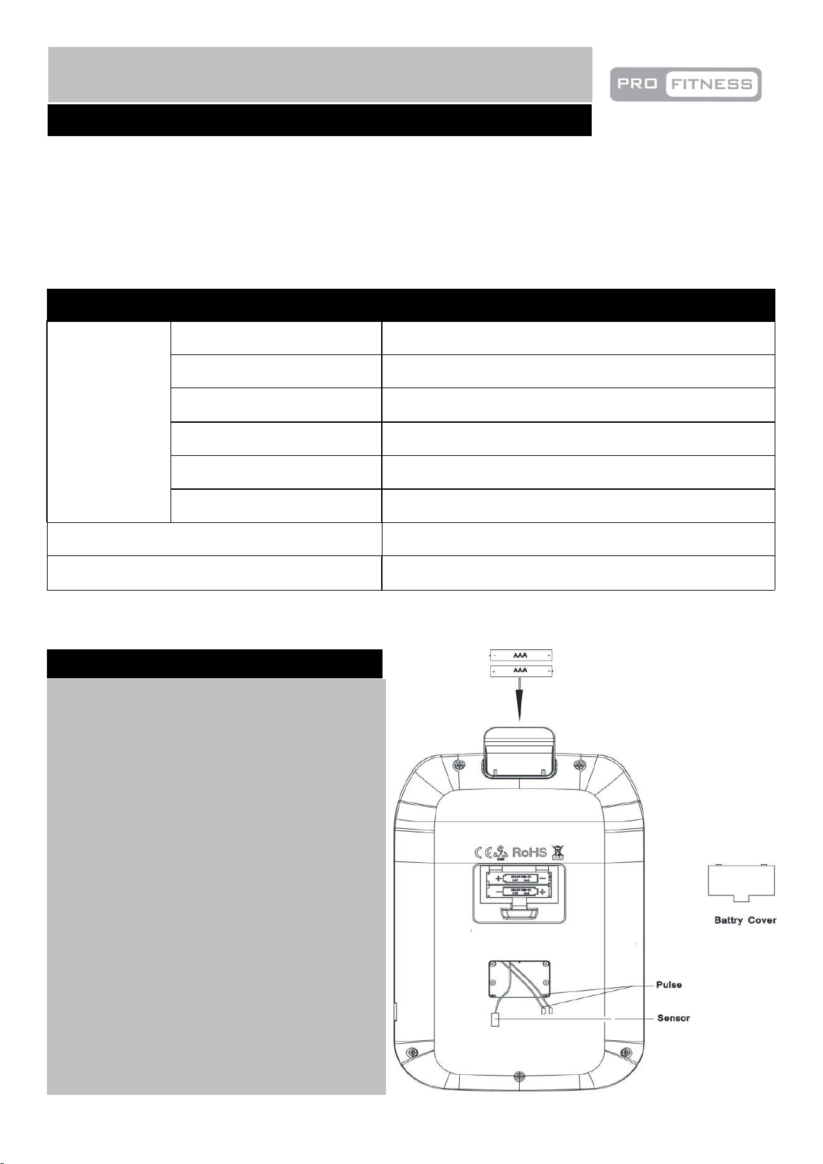
the heartbeat signal is received during the measurement.When no heart rate signal is input, the heart rate is
Specification
Function
Auto Scan
Every 6 Seconds
Speed
0.0 – 99.9 Km/h
Distance
0.0 – 999.9 Km
Time
00:00 – 99:59 (Minute: Second )
Calories
0.0 – 9999 Kcal
HR
0-240
Battery type
2 x SIZE – AAA
Operation Temperature
0℃ - +40℃
20
Replacement of the battery
A. Remove the battery cover on the back of the
computer.
B. Replace 1.5V (AAA) battery.
C. Make sure the battery is installed correctly
and the polarities are correct.
D. If the display is not clear or only partial
segments appeared, remove the battery and
wait for 15 seconds before re-installing it.
E. The battery life is approx. 10 months under
normal usage.
F. When the battery is removed, all the
functional values will reset to zero.
Exercise Information
Console Operation
displayed as P. Press UP or DOWN button one time, the heart rate will increase or decrease by 1 each time.
Long press for rapid accumulation or subtraction. Set the range of measurement heart rate, the
corresponding character flashing prompt when the measurement exceeds the preset range.
Page 22
`
Exercise Information
MAX
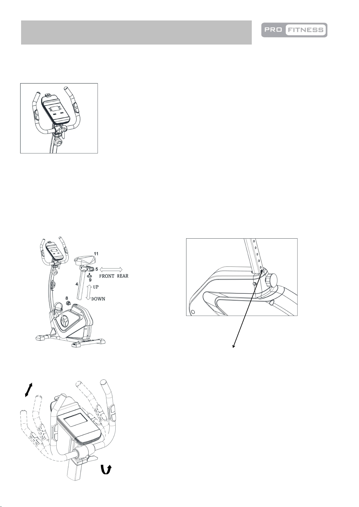
To adjust the position of the handle, turn the
lock knob (10) anti clockwise to loose the
handle (7) as shown in the diagram, and
adjust the handle (7) to your required
position, then secure the lock knob (10).
7
10
21
•Adjustment of the resistance
Adjustment of Resistance level by turning the 8-level tension knob either to the clockwise (increase) or
counter-clockwise (decrease).
•Adjustment of the seat
Unlock the M16 Lock Knob (8) and position the Seat Post (4) upwards or downwards at your required and
secure with the M16 Lock Knob (8).
Unlock the M10 Knob (9) and move the Saddle (11) forward or backward to a suitable position then tight
with M10 Knob (9).
Do not pull the Seat Post (4) beyond the MAX mark on the Seat Post (4).
Note: The seat height is correct when the knee is slightly angled with the pedal vertically down and the foot
parallel to the floor.
•Adjustment of the handle
Page 23
1. The safety level of the
equipment can only be
maintained if it is examined
regularly for damage and wear
e.g. ropes, pulleys and
connection points.
2. Lubricate moving parts
with light oil periodically to
prevent premature wear. To
prevent damage to the
computer, keep liquids away
and keep it out of direct
sunlight.
3. Inspect and tighten all parts
before using the equipment.
Replace defective
components immediately
and/or keep the equipment out
of use until repair.
4. The equipment can be
cleaned using a damp cloth
and mild non-abrasive
detergent. Do not use solvents.
5. Do not attempt to repair
this equipment yourself.
Should you have any difficulty
with assembly, operation or
use of your exercise product or
if you think that you may have
parts missing, contact
Customer Helpline:
0345 600 1714
www.argos-support.co.uk
Guarantee:
For guarantee purposes,
please retain your
purchase receipt.
Information for Users on Disposal of old Equipment and Batteries
These symbols indicate that equipment with these
symbols should not be disposed of as general
household waste. If you want to dispose of the
product or battery, please consider the collection
systems or facilities for appropriate recycling.
Service to this equipment should only be performed
by an authorized service representative, unless
authorized and/or instructed by the manufacturer.
Notice: The sign Pb
below the symbol for
batteries indicates that
this battery contains
lead.
22
Care and Maintenance
Page 24
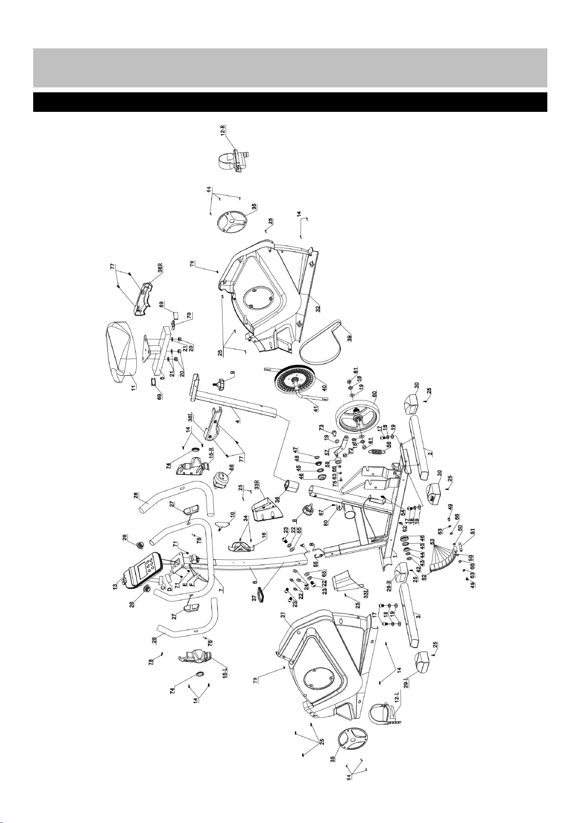
Exploded Parts Diagram
23
Page 25
No.
Description
QTY
SIZE
CODE
1
Main Frame
1
2A1205897
2
Rear Stabilizer
1
2A1205892
3
Front Stabilizer
1
2A1205891
4
Seat Post
1
2A1205895
5
Seat Adjustment Bracket
1
2A1205885
6
Front Post
1
2A1205898
7
Handle12A1205894
8
Lock Knob1M16
3C51JBD00101
9
Lock Knob1M10
3C51JBD00028
10
T Shaped Lock Knob
1M83C51JBD00042
11
Saddle13D71Q00024
12
Left & Right Pedal
2
3C51JBC00034
13
console13C300105
14
Philips Self -tapping &drilling Screw
8
ST4.2X15mm
3B55DDD00005
15L
Left Handle Cover
1
3C51JBG00016
15R
Right Handle Cover
1
3C51JBG00017
16
Bottle Holder
1
3D600024
17
Allen Bolt4M10X20mm
3B51DBD00205
18
Spring Washer
6
Φ10mm
3B53DIA00004
19
Washer7Φ10mm
3B53DIB00009
20
Nut (Zinc)3M8
21
Washer (Zinc)
3
Φ8mm
22
Spring Washer
4
Φ8mm
3B53DIA00009
23
Allen Bolt4M8X15mm
3B51DBD00203
24
Arc Washer
2
Φ8XR22mm
3B53DIC00014
25
Philips Screw
20
ST4.2X15mm
3B55DDA00009
26
Cone End Cap
2
Φ25mm
3C51JBB00141
27
Handle Pulse Sensor
2
3D23O00184
28
Handle Grip
2
Φ25X520mm
3C73K00041
29L
L Transport Wheel
1
3C51JBC00035
29R
R Transport Wheel
1
3C51JBC00036
30
Level Foot
2
3C51JBC00080
31
Left Cover
1
3C51JBG00666
32
Right Cover
1
3C51JBG00667
33L
Front L Post Cover
1
3C51JBG00668
33R
Front R Post Cover
1
3C51JBG00669
34
Philips Self-drilling Screw
2
ST4.2X15mm
3B55DDD00005
35
Crank Cover
2
3C59J00418
36
Sleeve13C51JBE00056
37
Front Post Ring
1
3C51JBG00672
38L
Left Saddle Cover
1
3C51JBG00670
38R
Right Saddle Cover
1
3C51JBG00671
39
Belt13D59P00001
40
Belt Pulley
1
3C59J00050
41
Crank13D600007
42
Lock Nut13D600008
43
C-Shaped Lock Ring
1
3D600008
44
Alex Sleeve
1
3D600008
Parts List
24
Page 26

45
Bearing23D600008
46
Bearing Chamber
2
3D600008
47
Lock Washer
1
3D600008
48
Right Bead Flange
1
3D600008
49
Hex Bolt2M6X15mm
3B51DBJ00083
50
Bead Flange
2
3B56D00014
51
Axle13B67E00203
52
Magnet Bracket
1
2A1300077
53
Magnet83F900023
54
Spring136mm
3B61EJZ00004
55
Tension Adjustable Cable
1
3C59J00420
56
Spring174mm
3B61EJA00005
57
Belt Tension Pulley
1
2A1205893
58
Tension Pulley Bracket
1
2A0600002
59
Spring Bead Flange
1
60
Fly Wheel
1
3D89R00007
61
Nut
2
M10
62
Clip33C59J00052
63
Spring Washer
3
Φ6mm
3B53DIA00007
64
Philips Self Tapping Screw
6
ST2.9X10mm
3B55DDB00014
65
Washer2Φ8mm
3B53DIB00010
66
Washer3Φ6mm
3B53DIB00067
67
Philips Bolt
1
M4X10mm
3B55DDB00007
68
Tension Knob
1
3C51JBD00048
69
End Cap
2
3C51JBB00138
70
U-Shaped Case
1
2A1300069
71
Dome Head Philips bolt
4
8MM
72
Nut
1
M10
3B52DCC00007
73
Hex Bolt1M10 x 25mm
3B51DBJ00084
74
Joint Ring
2
3C59J00417
75
Hex Bolt1M6 x 10mm
3B51DBJ00124
76
Philips Self Tapping Screw
2
ST4.2X20mm
77
Philips Bolt
4
M5×5
3B51DBF00029
78
Philips Bolt
1
M5×50
79
Philips Bolt2M5×10
3B51DBF00005
80
Reed Base
1
A
Lower Main Sensor Wire
1
3D22O00087
B
Reed Base Sensor Wire
1
3D22O00091
C
console Main Sensor Wire
1
D
Upper Main Sensor Wire
1
E
console Pulse Sensor Wire
2
F
Handle Pulse Sensor Wire
2
3D23O00184
25
Page 27
Guarantee
Product Guarantee
This product is guaranteed against manufacturing defects from a period of
This product is guaranteed for twelve months from the date of original
purchase. Any defect that arises due to faulty materials or workmanship
will either be replaced, refunded or repaired free of charge where possible
during this period by the dealer from whom you purchased the unit.
The guarantee is subject to the following provisions:
• The guarantee does not cover accidental damage, misuse, cabinet parts,
knobs or consumable items.
• The product must be correctly installed and operated in accordance with
the instructions contained in this manual.
• It must be used solely for domestic purpose.
• The guarantee will rendered invalided if the products is re-sold or has been
damaged by inexpert repair.
• Specifications are subject to change without notice.
• The manufacturer disclaims any liability for the incidental or consequential
damages.
• The guarantee is in addition to, and does not diminish your statutory or
legal right.
• In the event of problem with the product with in the guarantee period call
Customer Helpline: 0345 600 1714
Guarantor: Argos Ltd
489 – 499 Avebury Boulevard
Central Milton Keynes
MK9 2NW
Year
 Loading...