


FOR RESIDENTIAL
USER MANUAL
24V DC MOTOR
SWING GATE OPENERS
A4

INDEX
1.1 GENERAL PRECAUTION
1.2 INSTALLATION
A. STANDARD INSTALLATION
B. DIMENSION CHART
C. COMPONENTS OF INSTALLATION
D. INSTALLATION OF ARTICULATED ARM OPENER
E. WIRE CONNECTION
1.3 TECHNICAL FEATURES
A. DIMENSION
B. TECHNICAL FEATURE:
1.4 MAINTENANCE
1
1
1
2
3
3
4
4
4
4
5
A
1
1.2 INSTALLATION
1.1 GENERAL SAFETY PRECAUTION
5
WARNING :
This user manual is only for qualified technicians who is specialized in
installations and automations.
(1) All installations, electrical connections, adjustments and testing must be performed only after
reading and understanding of all instructions carefully.
(2) Before carrying out any installation or maintenance operation, disconnect the electrical power
supply by turning off the magneto thermic switch connected upstream and apply the hazard area
notice required by applicable regulations
(3) Make sure the existing structure is up to standard in terms of strength and stability
(4) When necessary, connect the motorized gate to reliable earth system during electricity connection phase.
(5) Installation requires qualified personnel with mechanical and electrical skills.
(6) Keep the automatic controls (remote, push bottom, key selectors…etc) being placed properly
and away from children.
(7) For replace or repair of the motorized system, only original parts must be applied. Any damage
caused by inadequate parts and methods will not be claimed to motor manufacturer.
(8) Never operate the drive if you have any suspect with what it might be faulty or damage to the system.
(9) The motors are exclusively designed for the gate opening and closing application, any other
usage is deemed inappropriate. The manufacture should not be liable for any damage resulting
from the improper use. Improper usage should void all warranty, and the user accepts sole
responsibility for any risks thereby may accrue.
(10) The system may only be operated in proper working order. Always follow the standard procedures
by following the instructions in this installation and operating manual.
(11) Only command the remote when you have a full view of the gate.
Please keep this installation manual for future reference.
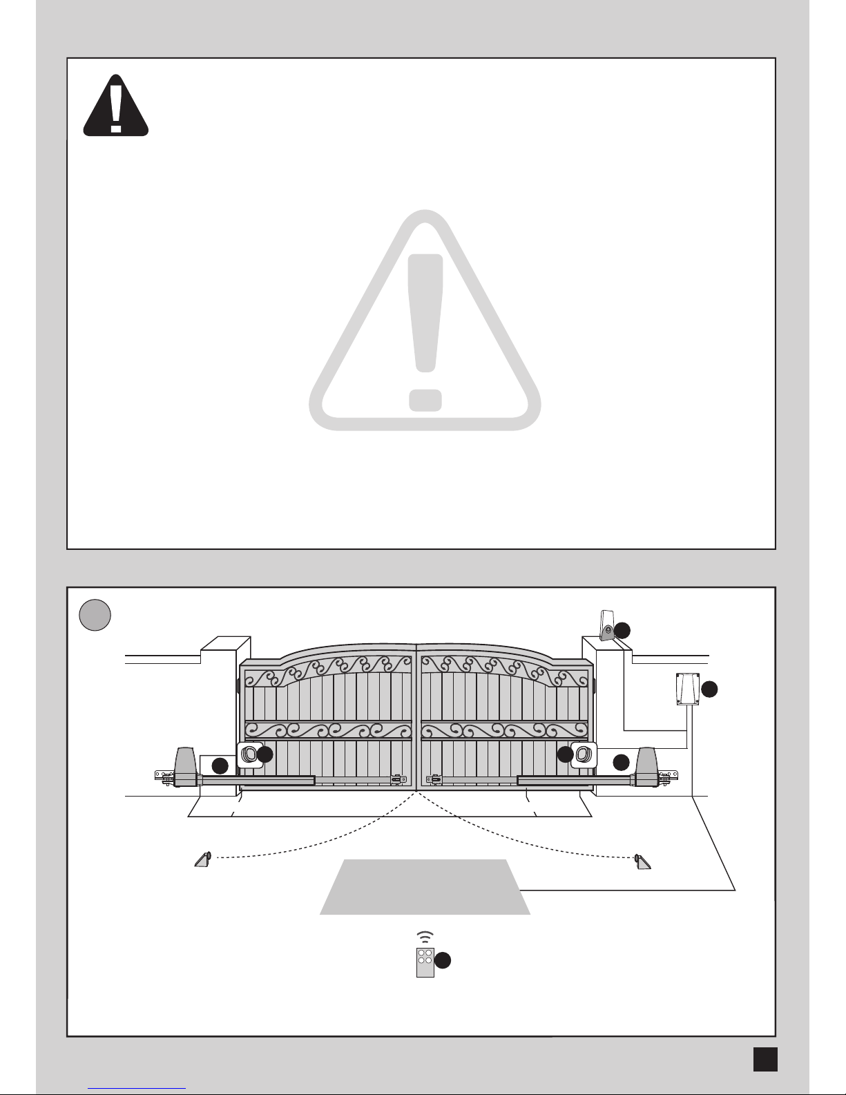
STANDARD INSTALLATION
2x1.5 mm
2
2x1.5 mm
2
TX - 4x0.5 mm
2
RX - 4x0.5 mm
2
3x1.5 mm
2
2x1.5 mm
2
2x1.5 mm
2
3
1
2
3
1. 24V DC blinker with antenna
2. Control Box
3. Photo Sensor
4. 24V DC gate opener
5. Transmitter
4
4

2
B
DIMENSION CHART
Comply with the measures shown on the chart for proper installation. Adjust the gate structure
to fit it for best automation, if necessary.
Before preceding the installation, be sure that gate moves freely and that:
1) Hinges are properly positioned and greased.
2) No obstacles in the moving area.
3) No frictions between two gate leafs or with the ground while moving

no.1
A
B
A
B
no.2
C
MOTOR FIXING
Assemble the rear bracket and fix it on the pillar.
D
WIRE CONNECTION:
3
141
125
156
Release the gate opener and place the pin into the fitting position no.1 and no. 2
Make sure the gate openers are mounted in horizontal position especially in those positions.
1) Gate in “CLOSE” position
2) Gate in “OPEN” position
3) Gate at “45。angle” position
Prior to weld the bracket on the gate leaf(if necessary), cover the gate opener to prevent
damages from sparks.
Note: Avoid tension in the cable during open and close phase.
M+(White)
M- (Yellow)

B
E
EMERGENCY RELEASE
4
1.3 TECHNICAL FEATURES :
TECHNICAL FEATURE:
DIMENSION:
In case of power failure or to program your automatic
gate, you can manually unlock the engines:
Stand in the inner side of the gate. Insert the hex
wrench for unlocking and then turn anti-clockwise
180 degrees. You can now open the gate by hand.
To lock again the engine, insert the hex wrench for locking and then
turn clockwise 180 degrees.
A
180
o
mm
200
118
797
Model
Gear type
Stroke
Power supply
Maximum gate weight
Maximum gate length
Duty cycle
Operating Temperature
Dimension
A4
Worm gear
435mm
24VDC
350KG
4meter
20%
-20℃~+50℃
797mm*118mm*200mm

5
1.4 MAINTENANCE:
Conduct the following operations at least every 6 months. If in high intensity of use,
shorten the period in between.
Disconnect the power supply:
(1) Clean and lubricate the screws, the pins, and the hinge with grease.
(2) Check the fastening points are properly tightened.
(3) Make the wire connection are in good condition.
Connect the power supply:
(1) Check the power adjustments.
(2) Check the function of the manual release.
(3) Check the function of photocells or other safety devise.

 Loading...