

Profire Energy PF3100, PF3100-00A/C, PF3101-00A Series Manual

PF3100 MANUAL
REV: 1.0
with UI, BMS Controller, Network Expansion,
Modbus RS-485, Ion Pilot, and Thermocouple Cards

IMPORTANT SAFETY INFORMATION
Ambient Operating Temperature Range -40°C to +60°C
GENERAL WARNINGS
Installation & use must conform to the directions in this guide.
System must be properly connected to earth-ground for effective operation of flame detection circuitry.
Electrical devices connected to the controller must meet certain electrical standards and be within voltage limits.
Replacement fuses must be ceramic and of correct rating.
Avoid unauthorized replacement of the fuse.
MODELS: PF3100-00A/C, PF3101-00A
Warnings
1. This equipment is suitable for use in Class I, Div 2, Groups A, B, C, and D hazardous locations or non-hazardous
locations only.
2. WARNING – EXPLOSION HAZARD – Do not disconnect equipment while the circuit is live or unless the area is
known to be free of ignitable concentrations.
3. WARNING – EXPLOSION HAZARD – Substitution of components may impair suitability for Class I, Div 1
hazardous locations.
MODELS: PF3102-00A
Warnings
1. This equipment is suitable for use in Class I, Div 1, Groups A, B, C, and D hazardous locations or non-hazardous
locations only.
2. WARNING – EXPLOSION HAZARD – Do not disconnect equipment while the circuit is live or unless the area is
known to be free of ignitable concentrations.
3. WARNING – EXPLOSION HAZARD – Substitution of components may impair suitability for Class I, Div 1
hazardous locations.
4. The flame rods are not intended to be installed and mounted in a Class I, Division 1 or Division 2 hazardous
location. Routing and installation of the flame rods shall be in accordance with the Canadian Electrical Code or
National Electrical Code as per local requirements.
5. CAUTION – Conduit seal required within 18” of enclosure. Div 2 seal not required.
MODELS: PF3103-00B
Warnings
1. This equipment is suitable for use in Class I, Div 1, Groups A, B, C, and D hazardous locations or non-hazardous
2. WARNING – EXPLOSION HAZARD – Do not disconnect equipment while the circuit is live or unless the area is
3. WARNING – EXPLOSION HAZARD – Substitution of components may impair suitability for Class I, Div 1
4. This assembly must be used with approved Profire probes and thermowells to maintain hazardous locations
locations only.
known to be free of ignitable concentrations.
hazardous locations.
certification.
E474004
PRIMARY SAFETY CONTROL
FOR USE IN HAZARDOUS LOCATIONS

TABLE OF CONTENTS
Introduction 1
Modules 1
Features 2
Specifications 2
Mounting Considerations 3
Installation Warnings 4
Wiring Pinouts 4
Wiring 5
PFRN Power and Communication 7
Display User Interface 8
Menu Map 9
Operation 15
Troubleshooting 16
System Errors 17
Resetting to Defaults 17
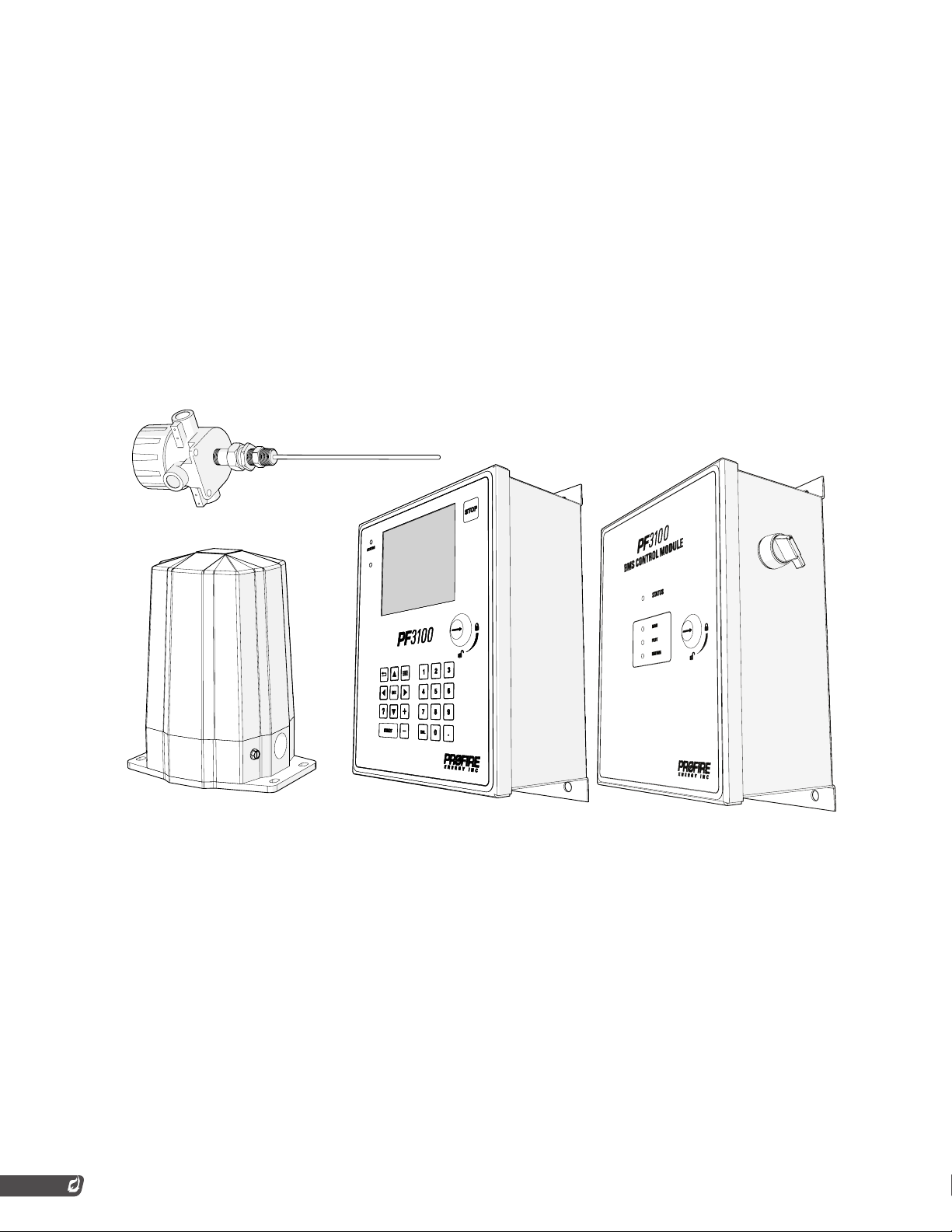
PF3100 MODULE FAMILY
INTRODUCTION
The PF3100 burner management system consists of individual building blocks called modules which can
be mixed and matched to form a complete solution. Each module performs a specific function and is
intended to be installed close to the device they are measuring or controlling. This simplifies wiring and
reduces issues with noise and signal loss compared to centralized control systems. This also allows the
user to purchase only the modules which are necessary for a given application. The modules interact with
one another using a network based communication method to perform a given task safely.
MODULES
UI Module
UI Network Module
UI BMS Module
UI BMS Network Module
UI Modbus Module
UI Modbus BMS Module
BMS Module
BMS Network Module
Ion Pilot Module
Type K Temperature Module
1

FEATURES
• Can view the status of other modules through the PFRN network from the UI Module
• Multiple UIs can show the same info on each screen
• Able to mount the UI away from the burner
• Simple indication of overall status through LEDs allowing end-users to check statuses from afar
• UI’s LCD screen shows statuses of overall system, individual modules, and groups of modules
• Numeric keypad is on the UIX enclosure for easy data entry
• Data logging and field firmware updates
• BMS modules in BMS enclosures can be placed near the burner housing away from the UI interface
• BMS Controller cards provide power to other modules through PFRN ports
• Network cards allow for connections to many other modules to form a single communication network
SPECIFICATIONS
Card Specs
Specs UI Card Network Card BMS Card Modbus Card Ion Pilot Card Thermocouple
Card Type Interface Network Controller IO IO IO
Power Method Power
Voltage Input 36 VDC through
Number of Ports 1 PFRN Port 5 PFRN Ports 5 PFRN Ports 4 PFRN Ports 1 PFRN Port 1 PFRN Port
Fuse Rating N/A 6.3 A 10 A 500 mA N/A N/A
Fuse Part
Number
Fuse MFG N/A Schurter Schurter Schurter N/A N/A
Consumer
PFRN
N/A 3412.0113.22 1.2514 3412.0113.22 N/A N/A
Power Producer Power Producer Power Producer Power
Consumer
12/24 VDC 12/24 VDC 12/24 VDC 36 VDC through
PFRN
Card
Power
Consumer
36 VDC through
PFRN
Enclosure Specs
Specs UIX Enclosure BMS Enclosure AUX Enclosure EPX Enclosure TLX Enclosure
Dimensions Width 30.9 cm
Hazloc Rating Class I Div 2 Class I Div 2 Class I Div 2 Class I Div 1 Class I Div 1
Operating
Temperature
Storage
Temperature
(12.15 in)
Height 23.4 cm
(9.23 in)
Depth 13.4 cm
(5.28 in)
-40°C to 60°C -40°C to 60°C -40°C to 60°C -40°C to 60°C -40°C to 60°C
-40°C to 60°C -40°C to 60°C -40°C to 60°C -40°C to 60°C -40°C to 60°C
Width 30.9 cm
(12.15 in)
Height 23.4 cm
(9.23 in)
Depth 13.4 cm
(5.28 in)
Width 30.9 cm
(12.15 in)
Height 23.4 cm
(9.23 in)
Depth 13.4 cm
(5.28 in)
Top Width 11.7 cm
(4.61 in)
Base Width 16.8
cm (6.63 in)
Height 21.7 cm
(8.53 in)
Depth 13.3 cm
(5.25 in)
(Body Type)
Standard ½” NPT
Head Connection
2

MOUNTING CONSIDERATIONS
Orientation
The UIX, CTX, and AUX enclosures should be mounted upright.
The EPX and TLX enclosures can be mounted in whichever direction makes sense for
the application.
Location
1. The UI Module is typically mounted in an operator-safe, easily accessible area. The
recommended mounting height is 1.5m (5ft) above where the operator will be standing
for ease of use. If there is a BMS card in the UIX enclosure with the UI card, then you
will need to adjust the location accordingly.
2. Mount any BMS enclosures near the corresponding valve train.
3. The Thermocouple card is included inside of a head connection (TLX enclosure) with a
thermocouple probe. The Type K Temperature module comes ready to install into the
thermowells of each tank. Install in a Div 1 rated thermowell.
4. The Ion Pilot module should be located within 50 feet of the pilot it is igniting.
5. The Network and Modbus cards will typically be mounted inside of a UIX, CTX, and AUX
enclosure. Must be within max PFRN run length of 250 ft.
HAZARDOUS LOCATION MOUNTING
In order to maintain the hazardous location rating for the EPX Enclosure, the following conditions must be
met.
The EPX Enclosure lid must be tightened down until it is flush with the base. The locking
screw must be installed into the base.
Each unused base port must be sealed with pipe plugs. Use our plugs or figure out
appropriately rated plugs that are equivalent.
Any base ports in use must be sealed within 18 inches of the EPX Enclosure. All fittings must
have at least 5 threads of engagement.
3
INSTALLATION WARNINGS
Before installing the PF3100, please review the following list of warnings.
Failure to observe the following may result in death, electrocution,
property damage, product damage, and/or government fines.
1. For burners greater than 12.5 MMBtuh, additional modules may be required for use with
the PF3100 system.
2. It is recommended that the low fire feature be used with anything above 1 MMBtuh. To
use the PF3100 on burners greater than 5 MMBtuh, the Proof of Closure feature must
be used.
3. Failure to properly ground the pilot assembly back to the PF3100’s Ion terminal may
result in accidental electrocution, product damage, or failure to ignite the pilot.
4. The PF3100 generates 20kV - 40kV at its high voltage output terminal which can cause
cardiac arrest. Do not touch or place any object near the ignition coil’s high voltage
terminal or connected ignition wire while the product is operating. Even without making
physical contact with the terminal, it is possible to draw a spark from several inches
away, especially if the pilot bracket is not properly grounded.
5. Make sure that the PF3100 enclosures are securely closed each time after opening
the enclosure. This protects the internal circuitry from moisture damage and other
environmental concerns. Moisture damage is not covered by the product warranty if the
door has been left open.
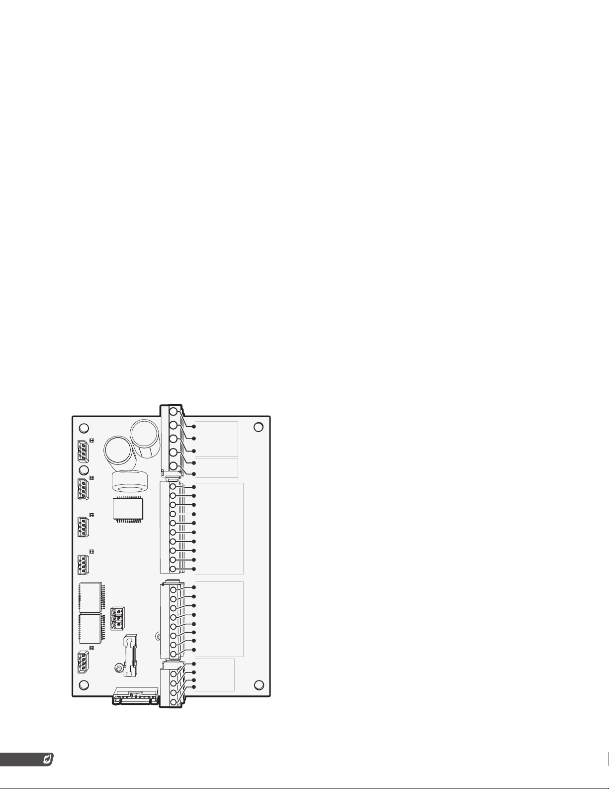
WIRING PINOUTS
/ VDC
/ VDC
COMMON
COMMON
EARTH GND
EARTH GND
STATUS
STATUS
HFV
HFV
HFV +
HFV +
SSV
SSV
SSV +
SSV +
SSV
SSV
SSV +
SSV +
Pilot -
Pilot -
Pilot +
Pilot +
Aux Out - (4-20mA)
Aux Out - (4-20mA)
Aux Out + (4-20mA)
Aux Out + (4-20mA)
START
START
START +
START +
POC
POC
POC +
POC +
AUX IN
AUX IN
AUX IN +
AUX IN +
ESD
ESD
ESD +
ESD +
PRESSURE
PRESSURE
PRESSURE +
PRESSURE +
LEVEL
LEVEL
LEVEL +
LEVEL +
Power
Power
Input
Input
Output
Output
Relay
Relay
Powered Outputs Dry Contact Inputs
Powered Outputs Dry Contact Inputs
Dry Contact
Dry Contact
4-20mA /
4-20mA /
Inputs
Inputs
*Output terminals are limited to 4A max current draw. 4-20 mA output terminals are limited to 20mA.
4
 Loading...