

Profi-pumpe PSM01134U, PSM01135U Operating Instructions Manual
Inverter pump control
Inverter pumpensteuerung
Version 18.12.
OPERATING INSTRUCTIONS
BEDIENUNGSANLEITUNG
de
Technical changes, misprints and mistakes reserved! Newest information about our products can be found online
Technische Änderungen, Druckfehler und Irrtümer vorbehalten! Aktuelle Informationen zu unseren Produkten nden Sie auf:
http://www.pro-pumpe.de
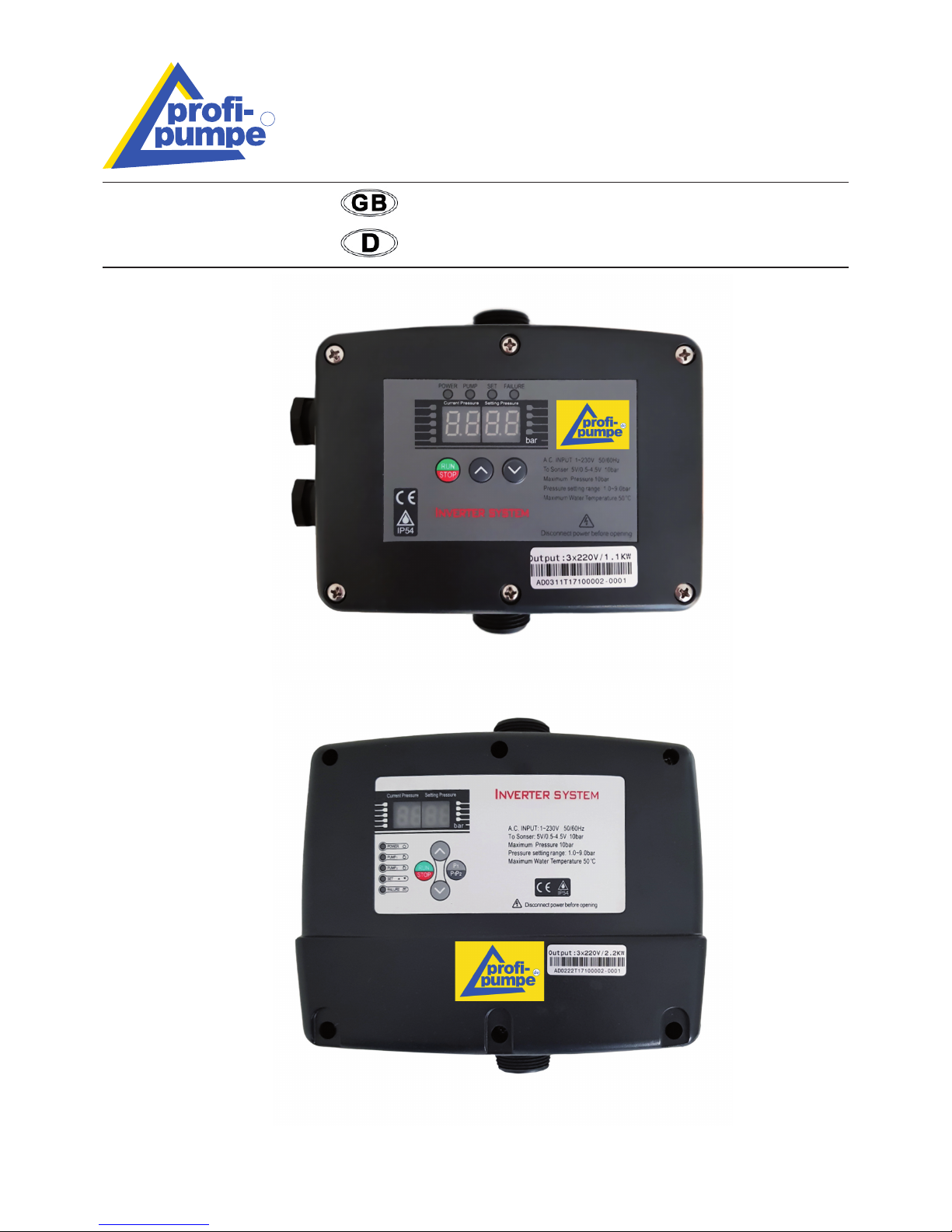
INVERTER-PUMPENSTEUERUNG 2-1,1KW
unverkabelt (IPC-2-UV)
(PSM01134U)
INVERTER-PUMPENSTEUERUNG 3-2,2KW
unverkabelt (IPC-3-UV)
(PSM01135U)
Contents
1. Introduction ......................................................................................................................... 2
2. In general ............................................................................................................................ 2
3. Installation ........................................................................................................................... 3
4. Wiring .................................................................................................................................. 3
5. Operation ............................................................................................................................. 4
6. Security tips ......................................................................................................................... 5
7. Servicing ............................................................................................................................. 7
8. Maintenance ....................................................................................................................... 8
9. Guarantee regulations ........................................................................................................ 8
10. Recognising and repairing of mistakes ............................................................................... 8
11. Notes on Product Liability .................................................................................................. 8
12. Notes on Disposal .............................................................................................................. 9
13. EU Declaration of Conformity ............................................................................................ 9
14. Technical Data ................................................................................................................. 20
2 English English 3
SAFETY INSTRUCTION AND WARNINGS
Please read the user manual
before using the device
Pull power plug
Warning sign Warning of electrical voltage
1. INTRODUCTION
We would like to congratulate you on the purchase of our Inverter pump control. We appreciate your
trust. That‘s why funtional security and operational safety stands by us on rst place.
To prevent damage to persons or property, you should read this user manual carefully. Please observe all safety precautions and instructions for proper use of the
device. Failure to follow the instructions and safety precautions can result in injury
or property damage.
Please keep this manual with the instructions and safety instructions carefully in
order to at any time you can restore them. Please always download the latest version
of the user manual of www.pro-pumpe.de under „downloads“. This shall always
prevail.
3. INSTALLATION
The installation must be performed by a qualied professional.
Please, check each time before using, the electrical connections and the cables are not
damaged. Check before the installation whether the electrical connections are earthed
according to the statutory regulations and are installed.
Also, it is NOT recommended to perform, for example, a cable extension. It is not certain
whether this modication is technically correct, so this warranty is void.
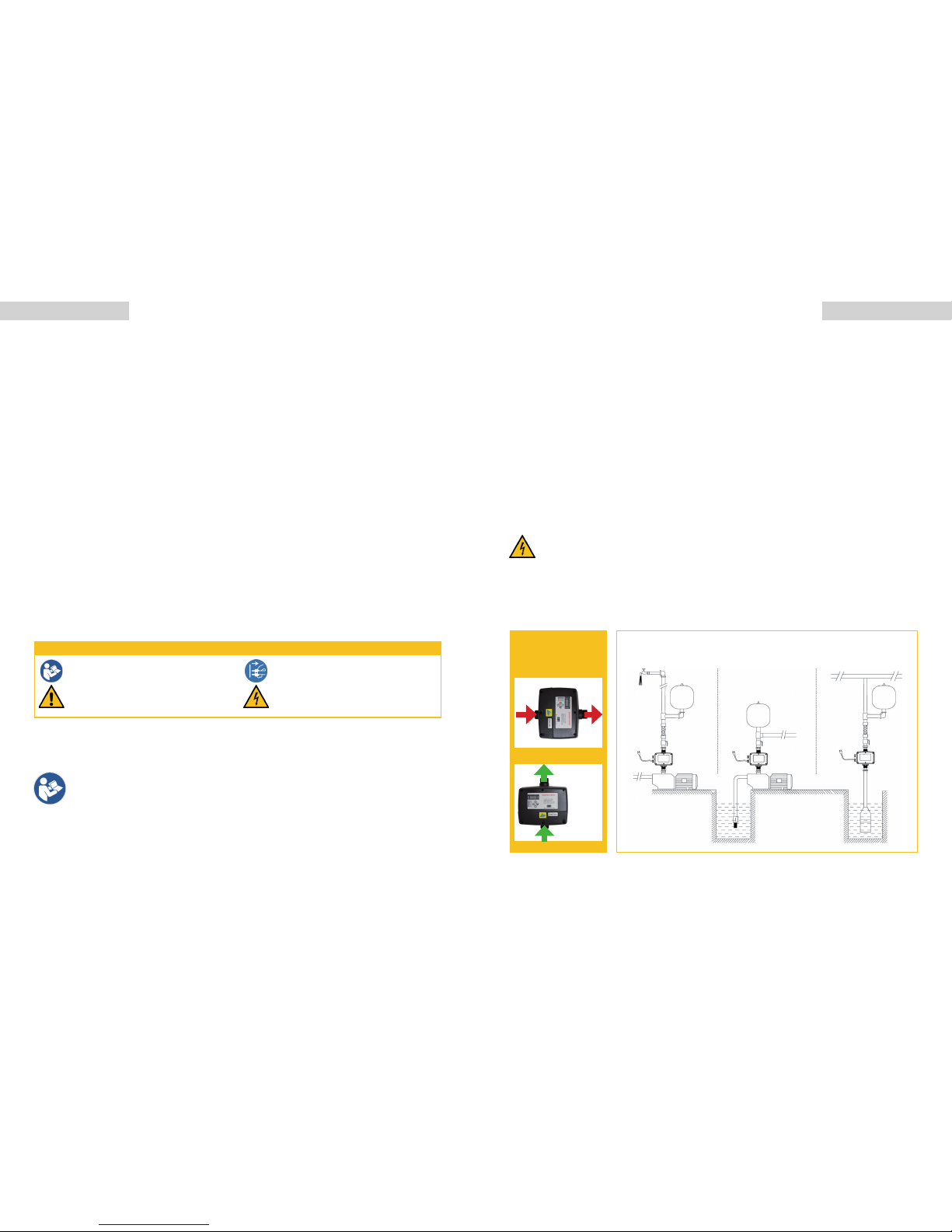
3.1 IPC-2-UV / IPC-3-UV
Single-phase Inverter
Water booster
installation mode
Self-priming pump
installation of water
supply mode
Submersible pump
installation of water
supply mode
The device must not
be installed horizon-
tally.
X
3
2. IN GENERAL
The inverter pump control is a switching device which can automatically switch an electrical consumer (pump) on and off. The device monitors the pressure and the ow in the pressure line. Depending on the pressure or the ow rate, it switches on and off of the inverter pump control one or more
electrical loads (MAX 10A) to the pump control.
The inverter controls can be easily operated with pumps with integrated non-return valve/ap can be
used.
The inverter pump control should only be used for non-abrasive clear water without deposits and
other dirt. In the opposite case, an effective pre-lter with a mesh size not larger than 0.2 mm must
be installed in front of the unit.
After unpacking the unit, make sure that the lter dimensions indicated on the nameplate are correct.
data correspond to the intended operating conditions. In case of doubt, do not operate the unit.
Transport damage must be reported immediately to the forwarding company and to us in writing.
PRESSURE
TANK
PRESSURE
TANK
PRESSURE
TANK
4 English English 5
INVERTER
PUMPENSTEUERUNG
IPC-2-UV / IPC-3-UV
Double Pump Installation
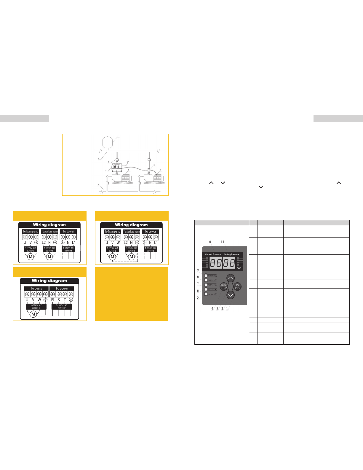
4. WIRING: IPC-2-UV / IPC-3-UV
Wiring Diagram and Instruction
Additionally
required parts
1. Ball valve
2. Check valve
3. Pressure tank
4. Inlet pipe
5. Inverter
6. Outlet pipe
7. Main pump
8. Auxiliary pump
Single-phase in and single-phase out
(with auxiliary pump)
Three-phase in and three-phase out
wiring diagram
Single-phase in and three-phase out
(auxiliary pump)
1. Don‘t connect the AC main circuit power
supply and output terminals U, V, W.
2. Wiring after the power cut off.
3. To verify the inverter rated voltage and the
input supply voltage are consistent
4. The inverter can‘t be done the dielectric
voltage withstand Test.
5. Terminal screw tightening torque 1.7N.m.
6. Make sure the ground terminal is connected
before wiring the main circuit terminals.
7. Connect the input power after installing the
panel,when the power is connected, don‘t
remove the panel
5. OPERATION
5.1 IPC-2-UV / IPC-3-UV
5.1.1 Checking before Operation
1. Check the input power and surroundings is comply with the conditions of using.
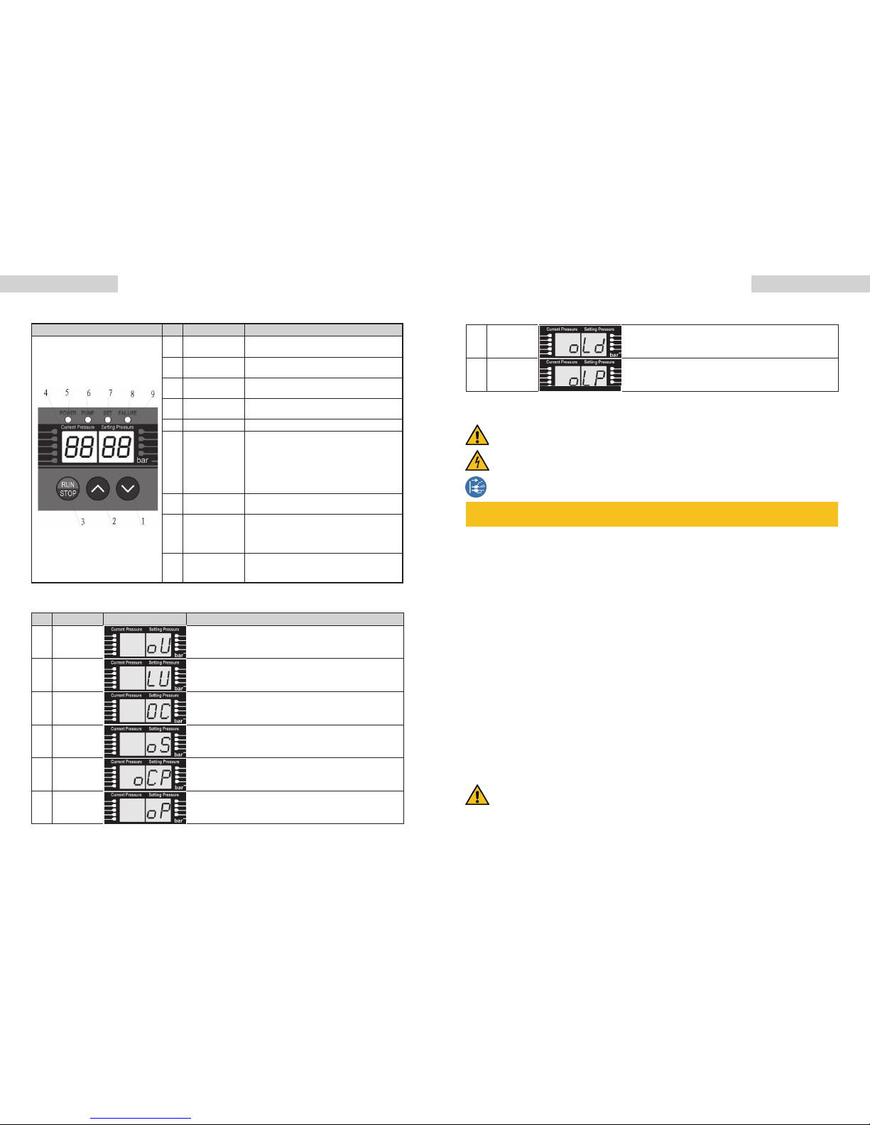
5.1.2 Button and Function Instruction PC-2-UV
Schematic Diagram No. Name or Function Instruction
1
Start or stop
button of auxiliary
pump
Start auxiliary pump manually, press it, the
pump runs
2 Reduce button
Press the button one time can reduce 0.1bar,
long time press can reduced rapidly
3 Increase button
Press the button one time can increase 0.1bar,
long time press can increase rapidly
4
RUN/STOP
button
It can start the pump manually, press this button
to exit the water shortage state
5
Water shortage
indicator
The indicator flash , it means the pipe is watershort. It will restart in setting time and the
interval time for restart is 8S, 1min , 10min ,
30min , 1h , 2h ....restart
6
Pressure setting
indicator
The light is flashing when working in the setting
pressure value
7
auxiliary pump
indicator
When the pump stop automatically,the indicator
lights,when stop pump manually,the indicator is off
8 Pump indicator
When the main pump speed operating state or
standby state,the indicator flash quickly.when
the main pump at the constant speed (constant
pressure) work state, the indicator flash slowly.
when the indicator is off,the main pump stop
9 Power indicator Indicator lights up when power is connected.
10
Current pressure
display
Display value indicates the current pipe network
pressure value,unit:bar
11
Set pressure
display area
Display value indicates the current setting
pressure value,unit:bar. Factory default Settings
is 3bar
2. Check whether the pressure sensor is connected with the system .
3. Check whether the product is installed rmly .
4. The pump starts (it is essential to refer to the operating instructions for the pump to nd out
what conditions must be met before starting up the pump) after connection is veried. If the
pump is three phase, please check whether the direction of motor revolve is correct. If the motor
rotates inversely, please exchange the terminal of UV, WV or WU, also it can be reversed adjust
through the slide switch.
5.1.2 Operating Steps
1. Connect power ,pressure display “00.00”bar, the power indicator lights.
2. Open the outlet valve,press “RUN” and start the pump
3. Any conditions can press “STOP”, and stop the pump
4. Press “
” or “ ” can check the working pressure, if want to change the pressure press “ ” to
increase the setting pressure or press “
” to reduce the setting pressure
5. Open the tap after setting pressure, the inverter will take frequency speed control on pump according to the water using status .Observing whether the pump is running normally, the pressure
showed in the display whether is constant. If it does, the installation and debugging is nished,
content to remove the faults and debug it again .
PRESSURE
TANK
6. SECURITY TIPS
l Obey absolutely valid regulations on the electrical security
l To avoid shocks and re risks, read and follow closely the following instructions:
• Always unplug the device from the mains before carrying out any work on it.
• Be sure that the electric line connecting the device to the mains and the extension
leads have a cross-section suitable for pump power and be sure that the electrical connections are far away from any water source
• When Flow guard is used for swimming pools, ponds and fountains if is necessary to
use an automatic RCD with IDn = 3OmA protection.
Warning: when the pump stops, the pipes are under pressure consequently we recom-
mend opening a tap to discharge the system before carrying out any work.
l The electrical connections are always to be carried out by an authorised professional.
l The device may be used by children aged 8 years and above as well as persons with reduced
physical, sensory or mental abilities or those who lack skills, experience and knowledge only if
they are supervised. These aforementioned persons should only use the appliance while adhering to safe instructions and resulting dangers.
l Cleaning and maintenance must not be carried out by children without supervision.
THE MANUFACTURER EXPLAINS:
l To take over no responsibility in the case of accidents or damages on the basis of carelessness
or disregard to the instructions in this book.
l To reject every responsibility for the damages which originate from the improper use of the device.
No. Code name Schematic Diagram Instruction
1
Over-Voltage
protection
When the voltage is higher than 270V shows this code, if the Voltage is lower than 260V, then recover to normal working situation
2
Under-Voltage
protection
When the voltage is lower than 100V shows this code, if the Voltage is higher than 110V, then recover to normal working situation
3
Thermal
protection
When radiator temperature get to 80 °C shows this code,if the
temperature lower than 60 °C,then recover to normal working
situation
4 Sensor error
When pressure sensor damaged or disconnect shows this code,
recover to normalworking situation after people check troubleshooting
5
Over pressure
protection
When pipe pressure equal to 99% of pressure sensor pressure
shows this code,if the the pressure lower than 96% of the pressure
sensor pressure,then recover to normal working situation
6
Open phase
protection
When inputed three phase power open phase shows this code,
recover to normal working situation after people check troubleshooting
7
Overload
protection
When exceed the setcurrent or load power shows this code, reco-
ver to normal working situation after people check troubleshooting
Over-current
When motor with short circuit or over-current problems shows
5.1.4 Code and Instruction IPC-2-UV / IPC-3-UV
No. Code name Schematic Diagram Instruction
1
Over-Voltage
protection
When the voltage is higher than 270V shows this code, if the Vol-
tage is lower than 260V, then recover to normal working situation
2
Under-Voltage
protection
When the voltage is lower than 100V shows this code, if the Vol-
tage is higher than 110V, then recover to normal working situation
3
Thermal
protection
When radiator temperature get to 80 °C shows this code,if the
temperature lower than 60 °C,then recover to normal working
situation
4 Sensor error
When pressure sensor damaged or disconnect shows this code,
recover to normalworking situation after people check trouble-
shooting
5
Over pressure
protection
When pipe pressure equal to 99% of pressure sensor pressure
shows this code,if the the pressure lower than 96% of the pressure
sensor pressure,then recover to normal working situation
6
Open phase
protection
When inputed three phase power open phase shows this code,
recover to normal working situation after people check trouble-
shooting
7
Overload
protection
When exceed the setcurrent or load power shows this code, recover to normal working situation after people check troubleshooting
8
Over-current
or short circuit
protection
When motor with short circuit or over-current problems shows
this code, recover to normal working situation after people check
troubleshooting
5.1.3 Button and Function Instruction IPC-3-UV
Schematic Diagram No. Name or Function Instruction
1 Reduce button
Press the button one time can reduce 0.1bar,
long time press can reduced rapidly
2 Increase button
Press the button one time can increase 0.1bar,
long time press can increase rapidly
3
RUN/STOP
button
It can start the pump manually, press this button
to exit the water shortage state
4
Current pressure
display
Display value indicates the current pipe network
pressure value,unit:bar
5 Power indicator Indicator lights up when power is connected.
6 Pump indicator
When the main pump speed operating state
or when motor is in speed governing state,the
indicator flash quickly. When the main pump at
the constant speed work state or water shortage, the indicator flash slowly. When it stop
automatically,the indicator is on. When it stop
manually ,the indicator is off.
7
Pressure setting
indicator
The light is flashing when working in the setting
pressure value
8
Water shortage
indicator
The indicator flash , it means the pipe is watershort. It will restart in setting time and the
interval time for restart is 8S, 1min , 10min ,
30min , 1h , 2h ....restart
9
Set pressure
display area
Display value indicates the current setting
pressure value,unit:bar. Factory default Settings
is 3bar
7. SERVICING
It may happen occasionally that dirt is retained in the internal check valve and this is no longer
seals 100%. The rst remedy should be always trying to ush the check valve free. For this purpose, eg. As the Garden side faucet on full blast, so that the pump at full rated power promotes
about 30 minutes water. Is then the timing is not clear, the unit must be replaced. Prior to installation of the new device, the pump is in, free to ush any case, as previously described. Opening the
device on non-return valve is prohibited and always results in the loss of any existing warranty. In
addition, persons could be dangerous when Operating a clocking pump occur, so that the pump
may be operated under any circumstances continue. Until the device replacement, the pump must
be taken out of service. For abrasive materials such as sand, shortening the Maintenance period
and the device lifetime.
The following checks should be carried out regularly:
l functional test (min. every 3 months)
l integrity of the power cord
l Clean the guide lines (eg no buckling)
l Clean the media (no sand, no sludge)
6 English English 7
 Loading...