

Page 1
DISARM
STATUS
POWER MONITOR
ALARM
SOS
Page 2
I. Features
II. Preparation before use
III. Host
1.LED status explanation
2. Host panel
IV. System Settings
1. Coding of wireless sensors
2. Exit coding
3. Settings by call
4. Settings by SMS
V. Operation Instruction
VI. Technical Parameters
VII. Standard Kit
VIII. Care and Maintenance
1
1
2
2
3
4
5
5
5
7
8
9
9
10
Page 3
Adopt GSM 850 900/1800/1900 bands, can be used all over the
world.
Can per-set 5 phone numbers: when there is an alarm, it will call
these numbers in order. Press DISARM button on the main panel, it
will stop alarming.
Can per-set 5 SMS numbers: when there is an alarm, it will send
SMS to these numbers.
Maximum 30 wireless sensors including wireless panic button or
remote controllers, etc.
2 wired ports to connect wired sensors.
The SMS content of the first 5 wireless sensors can be edited by
users.
Support remote listen in and two-way communication (connect an
external speaker).
SMS alert for power failure or recovery.
Built-in backup rechargeable battery to keep working after power off.
/
II
. Preparation Before Use
I. Features
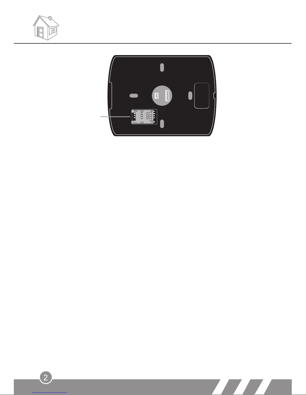
1.Insert SIM card in alarm system
Before inserting SIM card, please make sure:
---Use a regular mobile phone to set PIN code request to off
---Delete all stored numbers
---Make sure there's enough balance in the card to work normally
Open the outside case of the alarm system and put the SIM card into the
card slot (see picture).
Features
Page 4
2. Connect all devices needed
a. Connect the antenna
Screw the antenna to the unit carefully; do not over-tighten the
screw or leave it too loose!
b. Connect the alarm siren (optional)
c. Connect the two-way intercom speaker (optional)
d. Connect wired sensors (optional)
3. Power
Plug in the power adaptor and turn on the backup battery switch.
The LED indicator will flash and the unit enters standby status.
4. Do the needed settings (check Part “IV. System Settings” in
detail).
SIM card
Preparation before use
III
1.LED status explanation
. Host
Page 5
LED
LED Status
System working status
POWER
Off
Hasn’t turned on the switch; hasn’t
connected the power; no power in built-in
battery
Red
power supply is normal
STATUS
Red (flash quickly)
Check SIM card and search GSM network
Green (flash slowly)
SIM card and GSM signal are normal; have
stored numbers in SIM card; in arm status
Red
In coding status: wait to set sensors
Green (flash quickly) Sensor is set successfully
Red and Green flash
alternately
Receive correct setting SMS
MONITOR
On
Listen in status: users can hear the voice
from the scene
ALARM
On
Alarming status
Host
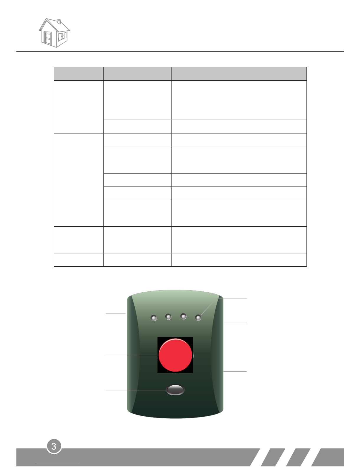
2. Host panel
DISARM
STATUS
POWER MONITOR
ALARM
SOS
MIC
Reset
External power
SOS button
Disarm
Status indicator
Page 6

SPK-
SPK+
2
GND
IN1
GND
OUT
GND
Wired port 2
GND
Speaker
IV. System Settings
This device has two passwords:
Remote control password: used for remote listen-in and two way intercom.
Default: 123456
Operation password: used for system settings. Default: 888888
System Settings
GND
Siren+
Siren-
Wired port 1
SPK- Negative of two - way intercom speaker (black cable)
SPK+ Posi tive of two - way intercom speaker (red cable)
IN2 Wired sensor 2
GND GND
IN1 Wired sensor 1
GND GND
OUT Positive of siren (red cable)
GND Negative of siren (black cable)
Note:
These two passwords could not be set as the same.
Page 7

1. Coding of wireless sensors
This device supports maximum 30pcs wireless sensors. Press the
[reset] button at the back side of the panel, there will be a shot beep
and the STATUS LED will be on red, indicating the device enters
coding status. Trigger the wireless sensor you want to code, there will
be a long beep and the STATUS LED will flash in green. The sensor is
set successfully.
The sensors will be numbered in consecutive order automatically
according to the coding sequence. That means, the first panic button
coded is No. 1, the second is No. 2, and the like. The default alarm
SMS is xx Emergency ALARM (xx means the serial number of the
sensor).
If the sensor quantity exceeds 30pcs, the exceeded sensor will replace
the coded one from No. 1.
2. Exit coding
In coding status, press [RESET] button again. Or if there's no operation
within 5 seconds after entering coding status, it will exit coding
automatically.
3. Settings by call
Users can use a mobile phone or fixed-line telephone to call the
number of the host to set alarm call numbers. It can store maximum 5
numbers. After setting, the host will call these numbers when alarm.
Setting method: after getting through the call, users will hear a long
beep. Then press operation password (default: 888888) and #. A long
beep means password is correct. Three short beeps mean password is
wrong, you need to input again. If the password is wrong for
consecutive three times, the call will be hung up automatically. If
there's no input within 30seconds after getting through the call, it will
also be hung up automatically.
After password and #, users can do the following settings.
Page 8

Table 1:
Function setting Setting format
Change remote control
password
30#[new password]#
Password should be
6-digit. Default: 123456
Change operation
password
31#[new password]#
Password should be
6-digit. Default: 888888
Alarm call number
setting
[50-54]#number#
50: the 1st number,
51: the 2nd number
…
54: the 5th number
Number should not exceed
20-digit.
Delete call number
[50-54]##
Alarm SMS number
setting
[55-59]#number#
55: the 1st SMS number,
56: the 2nd number
…
59: the 5th number
Number should not exceed
20-digit.
Delete SMS number
[55-59]##
Turn on power LED
00#1#
Default: on
Turn off power LED
00#0#
Power failure/recovery
alert
01#1# (ON)
Default: on
01#0# (OFF)
Alarm call circle time
02#[1-9]#
Default: 3
Siren rings when alarm 03#1#
Default: on
Siren off when alarm 03#0#
power supply is off, user will receive a message “POWER DOWN”. If
the power recovers after failure, the message is “POWER UP”.
b. Alarm call circle time: when there's nobody answers the alarm call, the
device will call all the alarm phone numbers in circle automatically. This
is to set the circle time.
Power failure/recovery alert: after activating this function, when the external
a.
Note:
Page 9

4. Settings by SMS
Use your mobile phone to send a message to the number of the
device.
All the above settings in Table 1 can also be set by SMS. And they
should begin with “operation password#”. The default password is
888888.
For example:
1. 888888#30#112233#:
change the remote control password into 112233
2. 888888#52#13412345678#:
set the third alarm call number as 13412345678
3. 888888#01#0#: turn off the function of SMS alert for power failure
4. 888888#02#5#: set the alarm call circle as 5 times.
All the following commands in Table 2 can also be set by SMS. The
SMS should begin with “operation password#”. The default password
is 888888.
Table 2:
Change alarm
button on main panel
message of SOS
96#message content#
Message content should
not exceed 25 English
letters. Default SMS: 00
Emergency ALARM.
Change alarm
panic button
[91-95]#message content#
message of wireless
91: the 1st wireless sensor
92: the 2nd wireless sensor
……
95: the 5th wireless sensor
Message content should
not exceed 25 English
letters. Default SMS: XX
Emergency ALARM.
XX means the serial
number of wireless sensor
Delete alarm
message
[91-95]##
Page 10

After successful setting, user will receive a SMS reply with the content
of “OK…”. If the SMS setting format is wrong, user will receive
“FORMAT ERROR!”.
Note:
V. Operation Instruction
1. Answer alarm call
When there is an alarm, the ALARM LED on the panel will be on and
the external siren (if user has connected) will ring for 3 minutes if
there's no operation. Also the device will send alarm SMS to and call
the preset numbers. Press DISARM button on the main panel or the
remote controller, it will stop the alarm.
The alarm system will keep calling all the preset numbers in order if
nobody answers the call. The default circle time is 3.
If someone answers the call, it will enter two-way intercom status
automatically and the siren stops ringing.
Then user can press “1#” to arm,
“2#” to disarm,
“3#” to listen-in,
“4#” to return to intercom.
A long beep means correct operation and three short beeps means
wrong operation.
Operation Instruction
5. Factory reset
Press the [RESET] button for 5 seconds until the LEDs on the panel are
flashing quickly. After this operation, all the settings return to factory
default.
2. Remote control operation
Operation by remote call:
When users are outside and want to monitor the alarm system, he can
call the alarm panel. After getting through the call, user will hear a long
Page 11

beep. Then press remote control password (default: 123456) and # to
enter listen-in status. User can hear the sound around the alarm panel.
If the password is input wrong, there will be three short beeps; while a
long beep means correct.
A long beep means password is correct, while three short beeps mean
wrong, you need to input again. If the password is wrong for
consecutive three times, the call will be hung up automatically. If
there's no input within 30seconds after getting through the call, it will
also be hung up automatically.
Power: DC12V/ 1.2A
Status current: ≤30mA
GSM bands: 850/ 900/ 1800/ 1900MHz
Wireless receiving frequency: 433MHz ± 0.5MHz
Receiving code: ASK
Wireless distance: no obstacle 80m
Working temperature: +10~+45℃
Working humidity: ≤90%
Backup battery: 7.4V/ 500mAh
VI. Technical Parameters
Alarm panel 1pc,
Power adaptor 1pc,
User manual 1pc.
VII. Standard Kit
Operation by SMS:
User can send sms to remotely arm or disarm the system.
Arm: remote control password (default: 123456)#1#
Disarm: remote control password (default: 123456)#2#
Technical Parameters
9
Page 12

VIII. Care and Maintenance
10
Page 13

11
Page 14

12
Page 15

2012 .07.V1. 0
 Loading...