

Page 1
ProfiDrum Page 1 van 20 © 2013
User Manual
Manufacturer information:
ProfiDrum
Lopik
Tel: +31 (0) 348-551801
E-mail: [email protected]
www.profidrum.com
Page 2

ProfiDrum Page 2 van 20 © 2013
Index
Introduction 3
Adjustments 3
Factory information 4
Contents of the package 4
Profile drumfilter 5
Connection to supply and drain pipes 6
Pump-fed arrangement 8
Connecting the waste disposel container on the sewer 10
Connecting the high pressure pump and spraybar 11
Controlbox 13
Connecting engines 10
Standard controlbox with opened case 14
Adjusting level probes and low water protection 16
Managing the controlbox 16
Test run after connecting the components 17
Intervals between rinses 17
Maintenance 17
Statement of marked points 17
Disclaimer 18
Important safety warnings 18
Final accountability 19
Page 3

ProfiDrum Page 3 van 20 © 2013
Introductie
Congratulations with the purchase of your ProfiDrum filter!
With the purchase of this drum filter you now own a high quality product which
was built with the utmost care and precision.
Please read carefully and follow all instructions and tips before you install the
drum filter.
If you have any questions, please do not hesitate to contact your dealer.
This manual is a simple guide to installing your drum filter.
We recommend making a copy of the manual to keep in the immediate vicinity of
your drum filter.
Our drum filters are suitable for gravity-or pump-fed lines.
Adjustments
Drum filters are in collaboration and marked with independent consultancy
Euronorm BV, CE.
Adjustments to Profi Drum drum filters that are made without the prior permission
of the manufacturer are not covered by the guarantee. When adjustments are
done without permission the CE marking,and guarantee expire.
Use only original spare parts supplied by us for repairs.
Spare parts can be ordered from the manufacturer or your dealer.
Page 4

ProfiDrum Page 4 van 20 © 2013
Factory information
You can find the type / model designation on the rating plate of your drum filter.
EC declaration
Manufacturer
ProfiDrum Holland
Sluisweg 5
3412 LA Lopik
Model Type: ProfiDrum 45/55/65/65E/75E
ProfiDrum model designation on the label on the drum filter
Applied CE Directives:
- New Machinery Directive (2006/42/EC)
- Low Voltage Directive (2006/95/EC)
- EMC Directive (2004/108/EC)
Applied standards:
- NEN-EN-ISO 12100-1
- NEN-EN-IEC 60204-1
The manufacturer declares to have complied with the safety requirements which
are determined from the safety requirements of the Machinery Directive. This
product also overlaps with the safety requirements from the LVD and EMC
directives.
Contents of the package
Your drumfilter is supplied with automatic control.
On all models a standard high pressure pump is supplied.
Page 5
ProfiDrum Page 5 van 20 © 2013
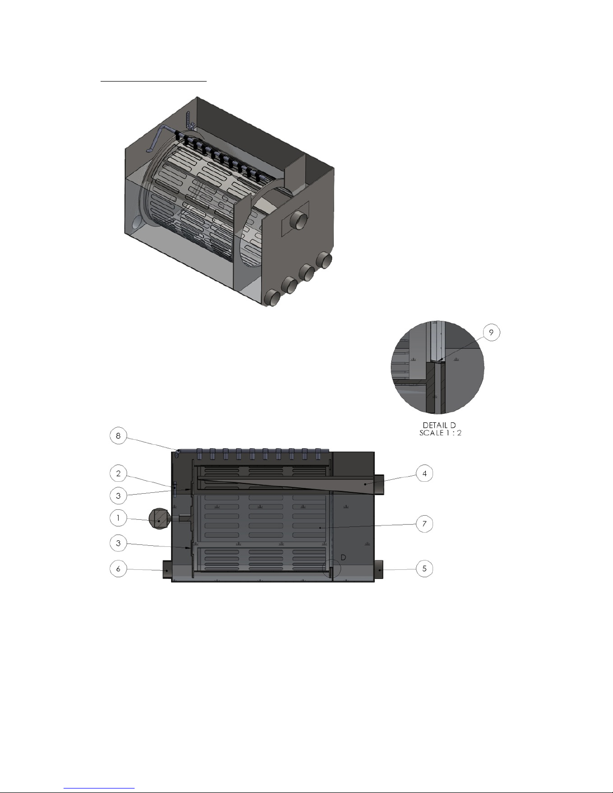
Profile drumfilter
1 Drummotor
2 Sensor
3 By-Pass
4 Waste disposel
5 Water imports, from pond
6 Water exports, to pump(s)
7 Drum with panels
8 Nozzles
9 Seal
Page 6
ProfiDrum Page 6 van 20 © 2013
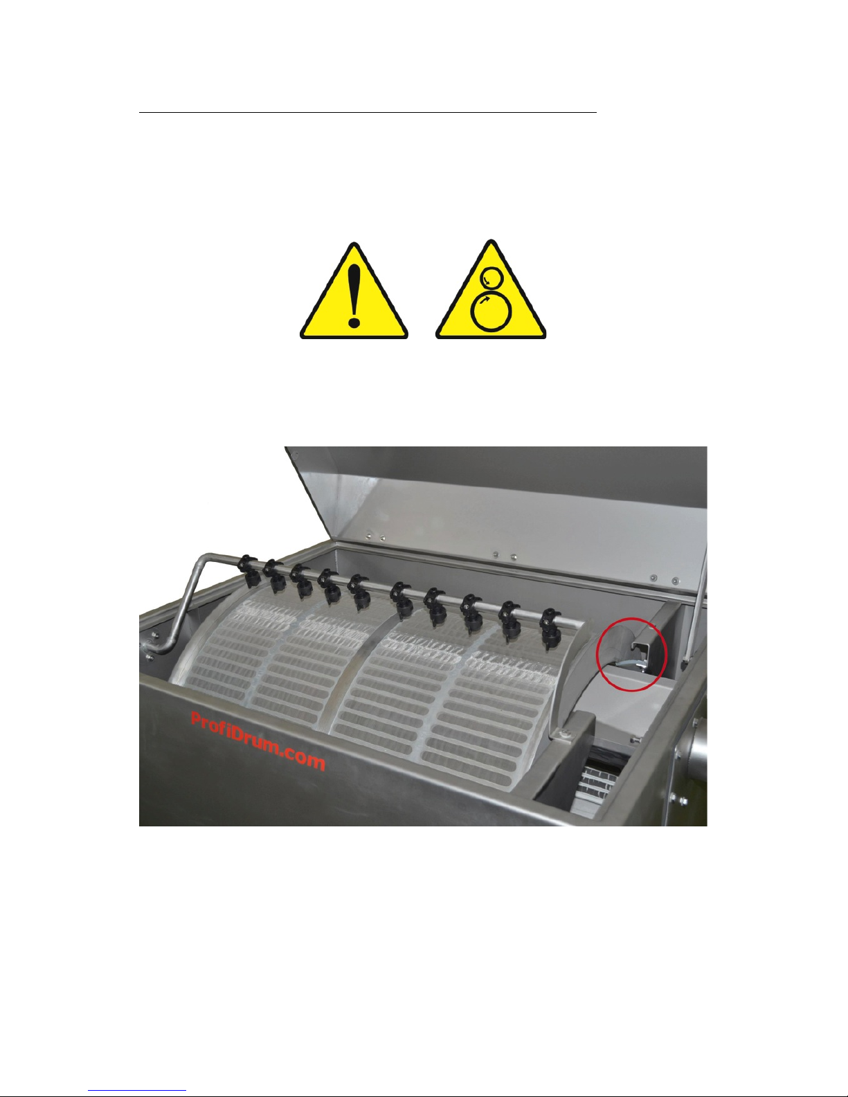
Connecting your drumfilter in GRAVITY arrangement
Place the drum filter on a solid surface that is completely level. You can then
connect the supply and return pipes * 1 of the drum to the pond or your filter. They
easily connect with sleeves and / or bends with a collar, or a rubber sock. The
size of the required PVC materials is 110 mm. It is advisable to place the landing
on the front side of the drum filter to provide a slide valve. Note: Always switch
off the control!
Set the drum so that the water level is even with the top of the silicone sealing
strip. By setting the water level at this height you use the most surface are of the
screen of the drum filter.
Water level adjustment
If you do not have enough supply piping, or the bends in the piping cause too
much resistance, there is the option to place the drum in such a way that the
water level is slightly above the top of the silicon strip (gravity situation) state.
Please note that all pumps are off.
Page 7
ProfiDrum Page 7 van 20 © 2013
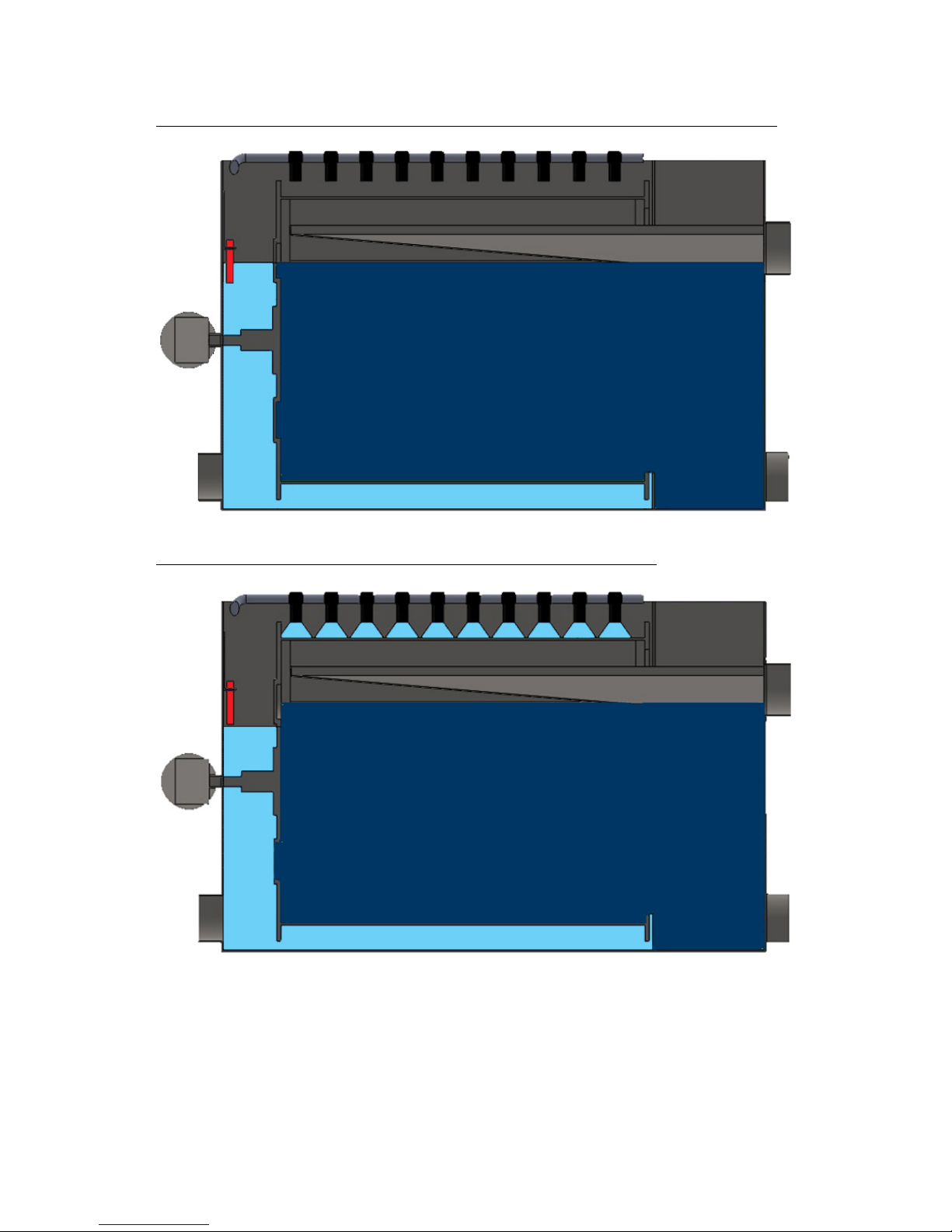
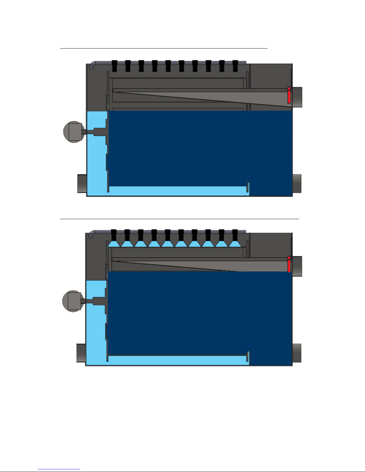
GRAVITY arrangement, not flush situation, probe touches water
GRAVITY arrangement, flush situation, probe is dry
Darkblue is not filtered water.
Blue is filtered water.
Page 8

ProfiDrum Page 8 van 20 © 2013
Pump-fed arrangement
1. Place the drum mesh tray on a solid surface that is completely level.
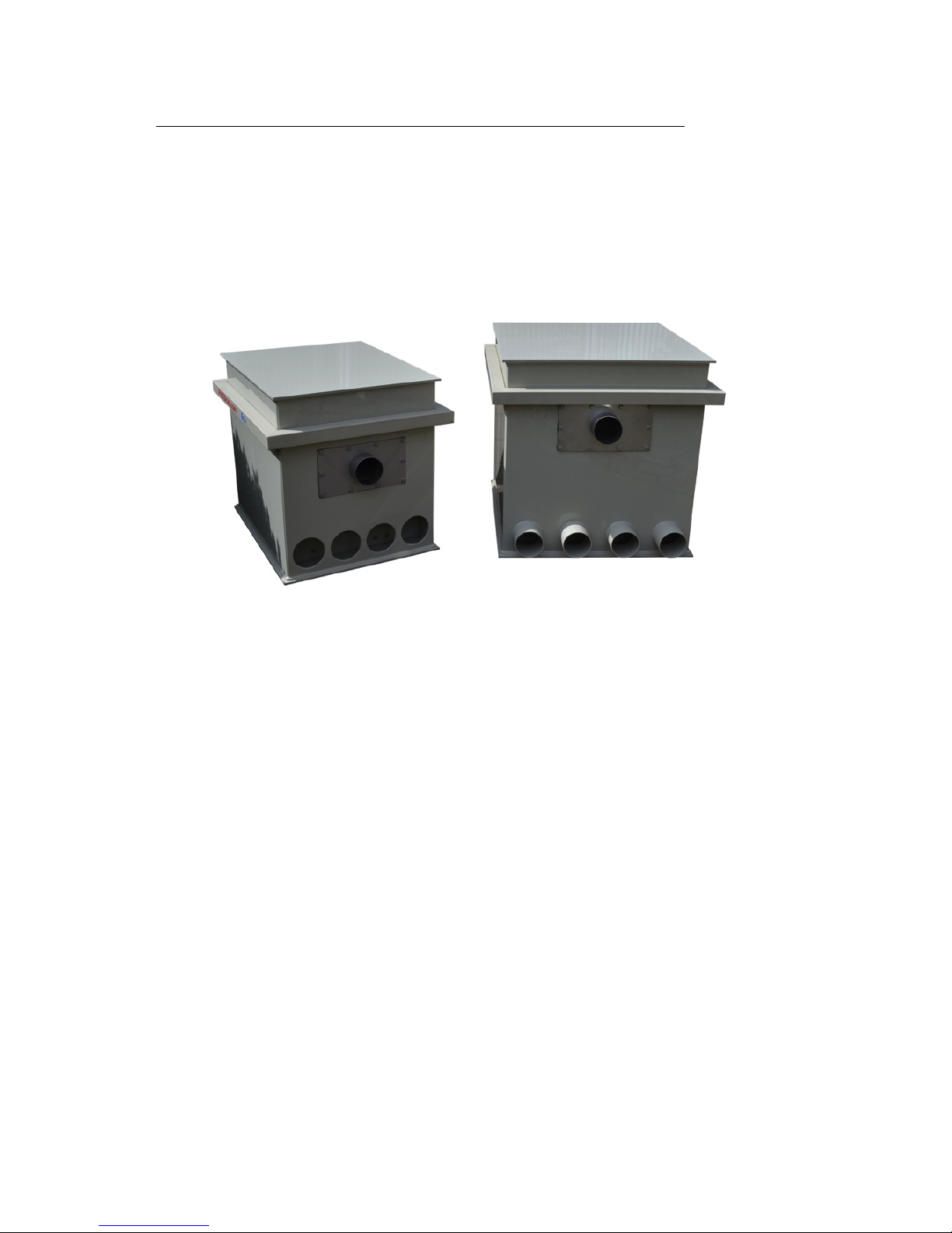
2. Connect a number of inputs to the front of the drum filter.
3. Then connect the pump(s) to one of the remaining input(s). If necessary,
you have to get an adapter to the connector of the pump you are using.
4. Then, extend the outputs on the back of the drumfilter in such a way that
the top of the outflow bend is at the same height of the top of the horizontal
beam at the front. Move the probe level of the back of the drum to the front
side of the drum in the collecting compartment.
Page 9
ProfiDrum Page 9 van 20 © 2013
Pump-fed arrangement, not flush situation, probe is dry
Pump-fed arrangement, not flush situation, probe touches water
Page 10
ProfiDrum Page 10 van 20 © 2013
Connecting the waste disposel container on the sewer
After connecting the supply tubes connect the tube * 2 (waste) to a drain pipe to
the sewer.
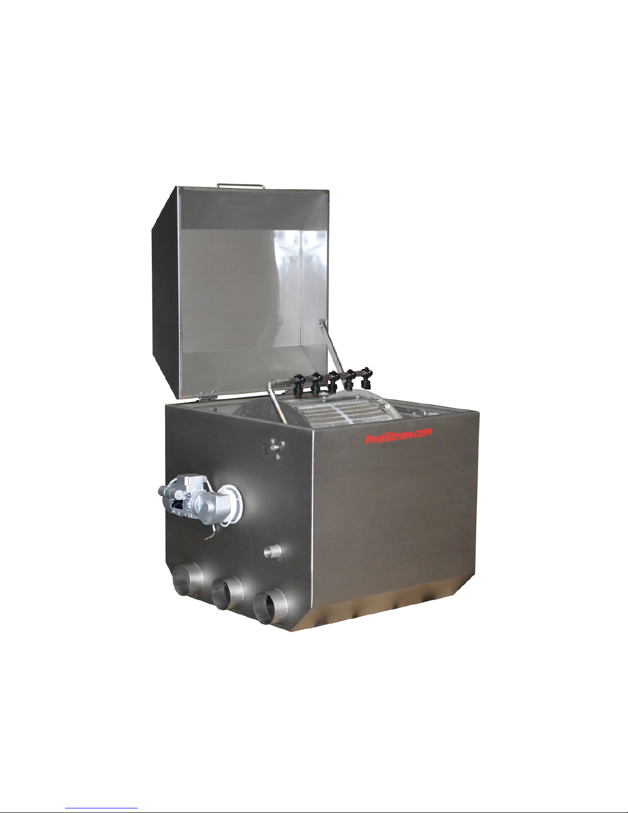
Front ProfiDrum Eco range.
Front of the drum connection with waste disposal,
top tube.
Page 11
ProfiDrum Page 11 van 20 © 2013
Connecting the high pressure pump and spraybar
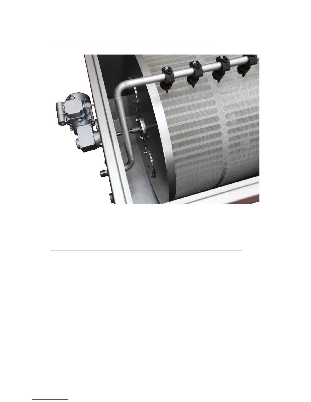
Spraybar with ½ inch connection.
Connecting the high pressure pump to the inlet of the drum.
If you only work with a high pressure pump, connect the vertical inlet (suction
side) of the high pressure pump (see picture pump) to the bottom of the drum 1
inch suction inlet
* 3
of the drum.
Page 12
ProfiDrum Page 12 van 20 © 2013
Suction and spray-bar connection to the drum filter.
Page 13
ProfiDrum Page 13 van 20 © 2013
Connecting the spraybar on the high pressure pump
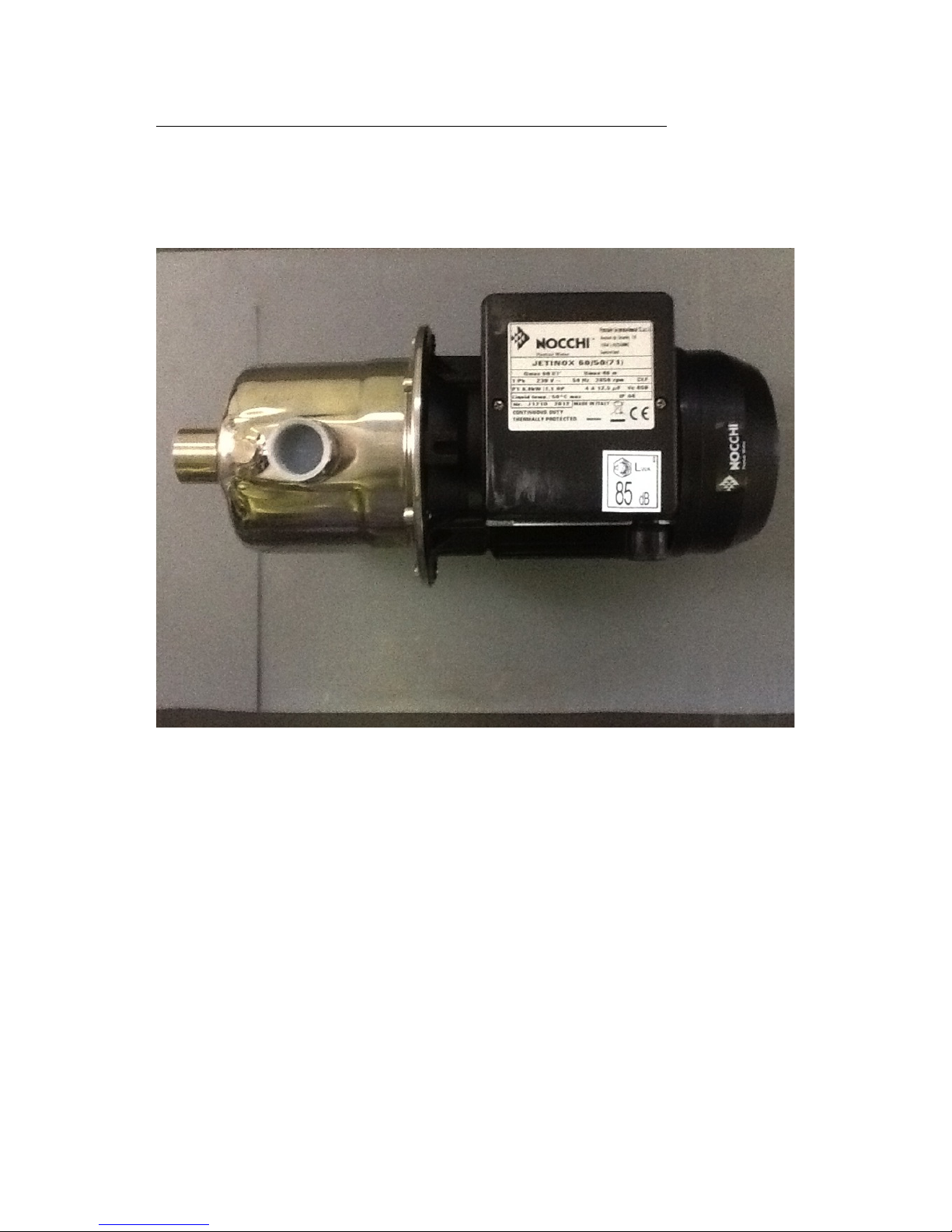
Then connect the discharge side of the high pressure pump to the spraybar. You
work with a high pressure pump and therefore it is advisable to work with flexible
hose. This prevents resonances in the pipes.
High pressure pump
Suction side is located on the front of the pump.
The compression side is located on the top side of the pump.
Page 14
ProfiDrum Page 14 van 20 © 2013
Controlbox
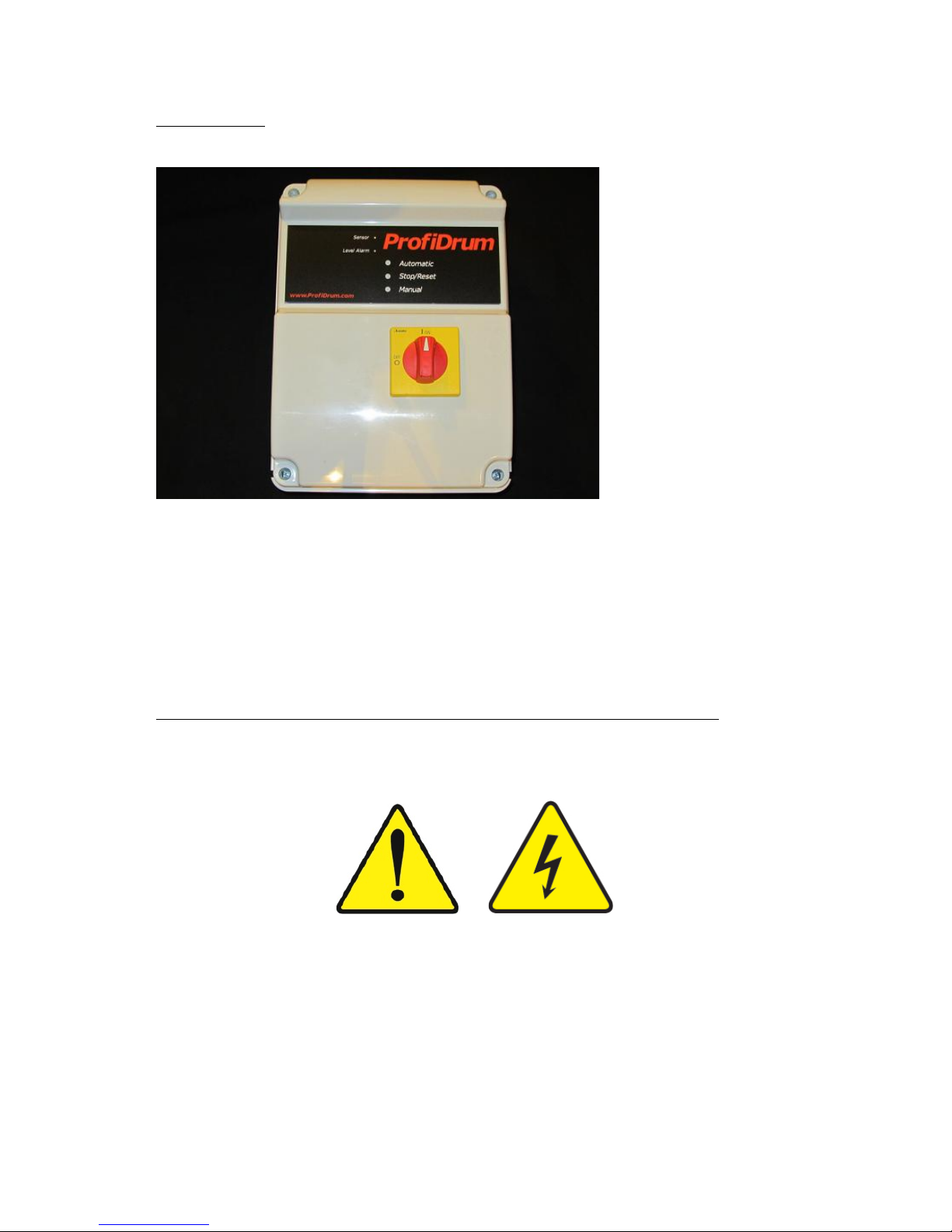
Control box
At the front of the control box are the:
- Main
- Automatic
- Stop/reset Switch
- Manual/test Switch
Connecting drum motor and high pressure pump on the controlbox
The box of your drum filter may differ. The drum filter is available with a standard
box or with a Siemens Logo PLC controlled system. This depends on the choice
of the box that you selected during the purchase.
Page 15
ProfiDrum Page 15 van 20 © 2013
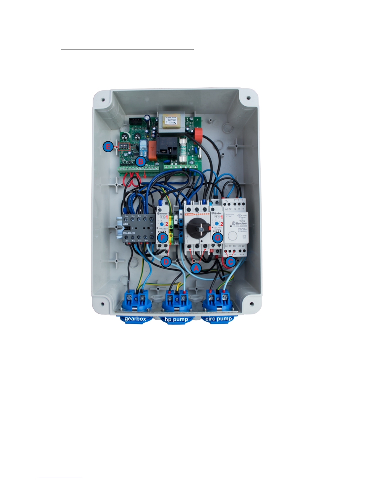
Standard control with opened case
Standard controlbox
Terminal hookup:
!
!
Explanation*
!
A!! ! Power!
B!! ! 7!and!9! ! Probes!
C! ! Switch!green!and!white!!cable!!
D! ! Mass!block!
E! ! 1!=!down.!2!=!up.!3!en!4!=!down!!!Gravity!
! ! 1!=!up.!2,!3!en!4!=!down!!!! Pumpfed!
F! ! Timer!for!rinsing.!1!=!hour.!2!=!percentage!!
G! ! Timer,!elimination!circulation!pump.!1!=!hour.!2!=!percentage!
Page 16

ProfiDrum Page 16 van 20 © 2013
A Power
B.1 High pressure pump
B.2 Gearbox
C 7 and 9 Probes
D 1 = down. 2 = up. 3 en 4 = down Gravity
1 = up. 2, 3 en 4 = down Pumpfed
E Timer
F Mass block
Page 17

ProfiDrum Page 17 van 20 © 2013
Connecting the motor and high pressure pump to the control box
1. Turn the main switch to the OFF position, and loosen the 4 screws of the
cover, and remove the cover.
2. Now connect the motor, high pressure pump, sensors and power supply to
the numbered items in the control box. The screws 3 and 5 on the PCB (A)
are used on the connecting cable from the probe to hold in place. This is a
connection with low voltage.
3. The wire of the high pressure pump relay block B 1.
4. The wire of the motor connects to relay block B 2.
5. The power supply connects to the relay block v.d. switch, Figure 1 and C 2.
6. Then connect all ground wires (green / yellow) to the ground block D.
Page 18
ProfiDrum Page 18 van 20 © 2013
Adjusting level probes and low water protection
Probes
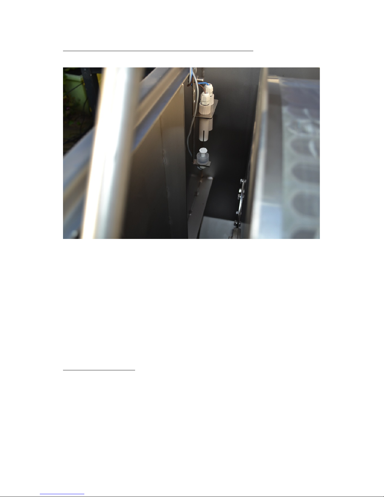
Your filter drum is equipped with two probes.
Once one of the 2 probes no longer in contact with water, the control box will turn
on your drum filter. It also turns on the high-pressure pump and cleans your cloth.
This cleaning process takes 10 seconds and during this process the contaminated
water is discharged through the waste piping. Ifyou want the intervals between the
flush times to lengthen or shorten, you can raise or lower the probe by hanging
the bracket in the predrilled holes.
You have a level height adjustment range of approximately 50 mm.
Dry run protection
For a small extra charge you can purchase an additional bracket and switch. You
connect the additional switch to the screws 1 and 2 on the green circuit board.
This switch must be attached 30 mm below the probe. See Figure 1 Figure 1 and
2 a 1
You should also remove the red wire.
Page 19
ProfiDrum Page 19 van 20 © 2013
Test run after connecting the components.
After connecting everything you should check the drum filter for correct operation.
It is wise to all check components and connections for leaks.
By turning the red safety button on the front control box to the ON position to set
the drum filter in operation.
Intervals between the rinses
It is normal that the drum filter in the early stage of filtering frequently rinses.
Unfortunately, there is no indication of why because this is highly dependent on
the situation. The intervals between the rinse cycles are therefore largely
determined by factors such as, pollution of the lake and its floating debris. Also,
the surface of the drum in combination with the fineness of the mesh, have direct
influence on the intervals between the flushing times. The intervals between the
rinsing times may also vary due to the seasons.
Maintenance
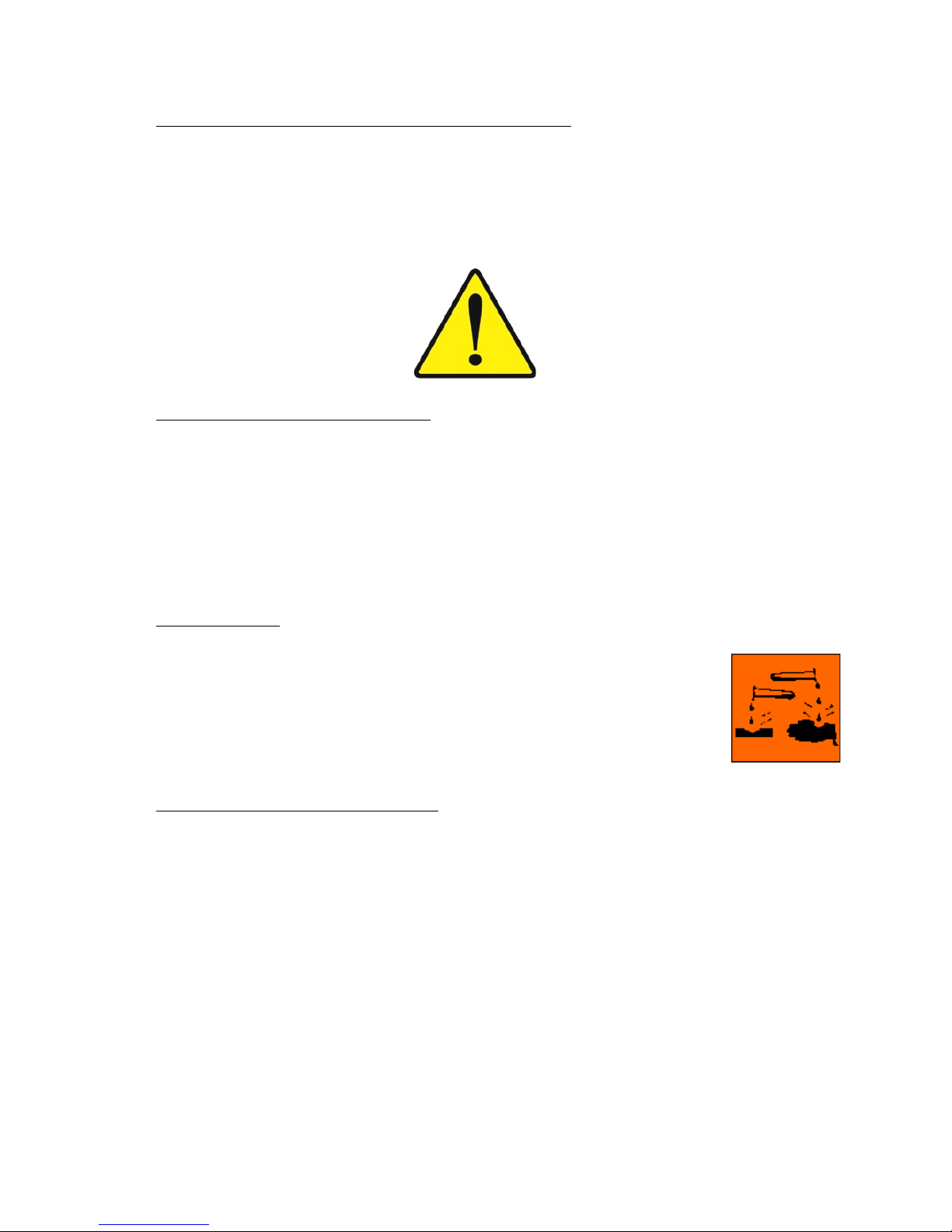
It is advisable to periodically clean the screen with a hydrochloric acid
solution <10. This maintenance should be done two to three times per
year, but is strongly dependent on the situation. In general, if the
intervals between the rinsing times become shorter, the cloth has to be
cleaned. Caution with hydrochloric acid. / It is corrosive, therefore
always take the appropriate measures.
Declaration of marked points
* 1
Exact size is 109 mm. It is preferred to work with a rubber cuff.
* 2
Diameter waste duct model ECO 45 is 90 mm.
All other models is 108 mm.
* 3
If your pond water is used for rinsing, it is recommended that a refill system
turns on to bring up your water level automatically.
Page 20
ProfiDrum Page 20 van 20 © 2013
Disclaimer
1. This disclaimer applies to:
• the owner: the owner of the website;
• user(s): all possible actions;
• you: the user of this information and our products;
• the content: all that the website contains;
2. The following applies to the page you are currently viewing. Our guide and
this page, you agree to this disclaimer.
3. The content has been put together by the owner with the utmost care,
however, the owner accepts no liability for any inaccuracies in the
displayed.
4. The owner is not responsible for content on this website linked files and / or
websites referenced.
5. Unauthorized or improper use of the content or parts thereof infringe
intellectual property rights
6. Permission to use the displayed content or parts thereof in public places
must be requested in writing to us.
7. See our terms and conditions.
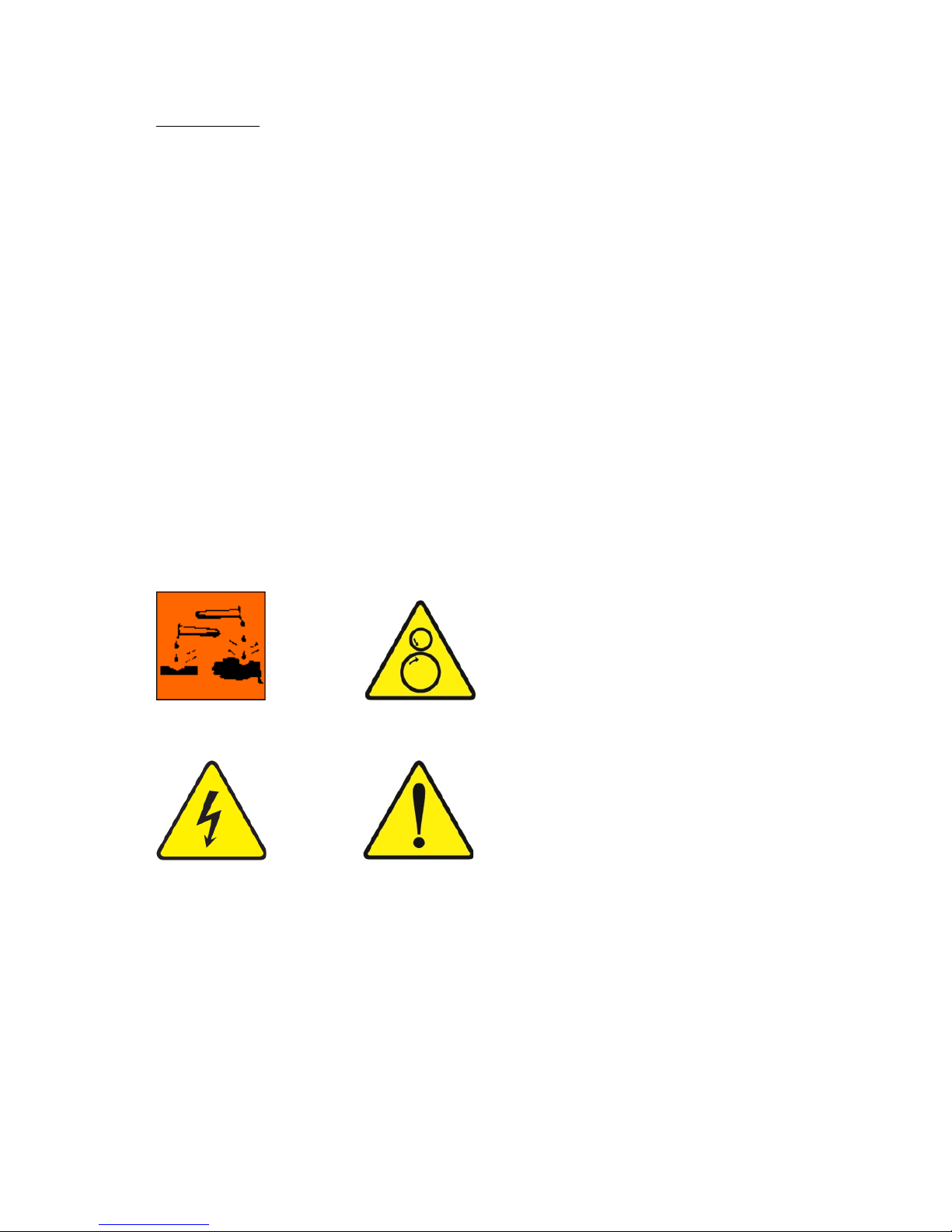
Important safety warnings
Corrosive substances Rotating / moving parts
Electrical hazard Danger
ProfiDrum is not liable for damages or injuries that occur as a result of not
correctly following and / or neglect of the directions that are prepared in the
Professional Drum manual.
All rights are expressly reserved to Profi Drum.
All our deliveries are general conditions apply.
 Loading...