

Proficient H2O Pro315 Next Gen TA HE Alternating Manual
Pro315-TA Twin Alternating Manual
404 Moravian Valley Road • Waunakee, Wisconsin 53597
Phone: 608-849-3459 • Web: www.procienth2o.com
Consumer Manual
Manufactured by:
PROFICIENT H2O
p/n 800705 Rev. C
Updated 10/24/17
©2015-2017

This manual is designed to assist owners and installers with the operation, maintenance and installation of your new water softener.
It is our sincere hope that this manual is clear, concise and helpful to both owner and installer. We have included detailed instructions on
general operating conditions, pre-installation and installation instructions, start-up, and timer and meter programming. We have included
a troubleshooting guide, service instructions and parts diagrams to assist you.
Owners will appreciate the simplied, illustrated format for operation, programming and troubleshooting. In the event that you need
professional assistance for servicing your water softener, please contact the dealer who installed this system.
TABLE OF CONTENTS
Job Specication Sheet ........................................................................................................................................................................... 2
Soft Water Basics ....................................................................................................................................................................................3
Operating Conditions ............................................................................................................................................................................... 3
Pre-Installation Check List ....................................................................................................................................................................... 4
Bypass Valve Operation ..........................................................................................................................................................................4
Installation Instructions ............................................................................................................................................................................ 5
Programming ........................................................................................................................................................................................... 6
Set Time of Day / Installer Settings .........................................................................................................................................................7
Salt Monitor Options / Cycle Adjustments ...............................................................................................................................................8
Softener Set-Up ..................................................................................................................................................................................8-12
Diagnostics ............................................................................................................................................................................................ 12
Valve History ..........................................................................................................................................................................................13
Cycle Sequence ...............................................................................................................................................................................13-14
Water Softener Disinfection ...................................................................................................................................................................15
Water Softener Draining Procedure ......................................................................................................................................................15
Troubleshooting ................................................................................................................................................................................16-18
Parts Diagrams .................................................................................................................................................................................19-26
Specications ........................................................................................................................................................................................27
Warranty ................................................................................................................................................................................................28
JOB SPECIFICATION SHEET
MODEL NO. __________________________________________________________________________________________
*WATER TEST AT TIME OF INSTALLATION
_______ Hardness CaCo
_______ Iron (ppm) ______ Other______________________
_______ pH ______ Other______________________
*SIZING INFORMATION
All Water is Softened Except:
_______ Rear Hose Bib _______ Front Hose Bib _______ Kitchen Cold _______ Toilets _______ All Cold
_______ Other ________________________________________________________________________________________
The average family uses 50 gallons per person daily for all water uses in the home, about 40 gallons per person daily if soft water
is not supplied to the toilets, and about 25 gallons per person daily if only hot water is softened.
_______ Daily Water Usage (Gallons/Person)
x _______ Family Size (Number of people in family)
= _______ Total Gallons Per Day
x _______ Grains Per Gallon of Hardness
(Note: Add 3 grains per gallon of hardness for each ppm iron for total compensated hardness)
= _______ Total Grains Per Day
(gpg) ______ Other______________________
3
*INSTALLATION DATE ____________________________ *SERIAL NUMBER ____________________________________
2
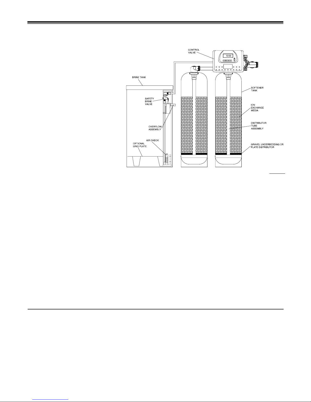
Hardness
Excess amounts of calcium and magnesium in
water produce hardness. A water softener removes
the majority of calcium and magnesium to produce
softened water.
Hardness is measured in terms of grains. (This
grain weight is derived from the average weight
of a dry grain of wheat.) When water is tested
the grain hardness is calculated and expressed
as grains per gallon (gpg). This calculation, as
well as the number of people in the household or
business will help determine what type and size
of water softener will most efciently soften your
water.
Your water softener contains an ion exchange
media (often called resin) which removes the hardness from water as it ows through each softener
tank. Eventually so much hardness collects on
the exchange media that the softener can no
longer soften the water in that tank. At this point
it is considered "exhausted". The twin alternating
function automatically switches to the standby
tank and regeneration occurs immediately on the
exhausted tank.
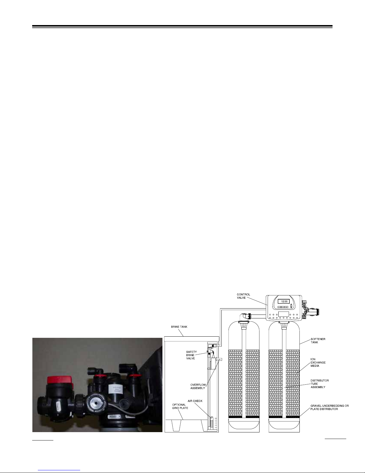
SOFT WATER BASICS
Figure 1
Regeneration
To regenerate the exchange media, it must be rinsed with a brine (salt) solution. This removes the hardness from the exchange media
and replaces it with sodium. The exchange media is then ready to remove hardness from water. The hardness minerals and excess
brine solution are rinsed down the drain.
During the regeneration cycle the softening media is also backwashed. This reversing of the normal ow of water serves to remove
sediment which may have accumulated during the softening process due to the ltering action of the exchange media. Backwashing
also loosens and uffs up the bed of exchange media to insure that during regeneration the brine solution will come into contact with all
the media.
Maintenance of Your Softener
Salt: Salt to a softener is what gasoline is to a car. Not only must a softener have salt, but it should be the proper type to insure
efcient recharging of the unit. Ask your dealer what type of salt may best suit your needs. Always have an adequate supply of salt on
hand. Check the salt level of your brine tank every couple of weeks initially to determine how much salt you use - this will depend on
how much water you use. As a rule of thumb, with 20 gpg hard water, about a 1/2 lb. of salt per person per day is used. In other words,
a family of four uses 60 lbs. of salt a month. Fill the tank approximately three-fourths full, with a minimum of 12” of salt. DO NOT USE
Block Salt when the Pro315-TA Series control is programmed for prell. Block salt does not dissolve quickly enough to provide a good
regeneration. If using Block Salt, Pro315TA Series control must be programmed for post ll.
Cleaning Salt Tank: The salt tank may require periodic cleaning. Inspect the salt tank at least once a year for buildup of insoluble
materials. It is recommended to periodically clean the salt tank no matter what kind of salt you are using. See page 15, Miscellaneous
#2 for details on cleaning.
REMEMBER: Salt is the fuel to run your water softener. Buy the best clean salt available.
OPERATING CONDITIONS
Your water conditioner has been designed to adequately
handle up to 40 grains per gallon of hardness as well as up to
0.5 ppm of ferrous bicarbonate iron. This is iron that is dissolved
in water and not visible to the eye in a freshly drawn sample.
After standing in contact with air, the ferrous iron will become
oxidized to the ferric state and start to precipitate as a reddish
brown oc. It can be seen and may cause discolored water. In
order for your softener to remove the iron, air (oxygen) must be
kept from coming in contact with water until after it has been
passed through the water conditioner. In some cases, additional
equipment may be required to treat water supplies having special
characteristics, such as: ferric hydroxide iron, iron bacteria, low
pH, taste and odors, etc. If any question should exist, contact
your dealer.
This water softener is not intended to be used for treating
water that is microbiologically unsafe or of unknown quality
without adequate disinfection before or after treatment.
3

(All electrical & plumbing should be done in accordance to all local codes)
PRE-INSTALLATION CHECK LIST
Water Pressure: A minimum of 25 pounds of water pressure
(psi) is required for regeneration. Maximum 125 psi.
Water Quality: On rural water supplies there is often a problem
with sand or sediment in the water. (This problem occasionally
occurs in public water supplies.) If the water is not ltered before
being softened, the sand and sediment may plug up the water
softener restricting the ow through the resin bed. This problem
often requires rebedding of the mineral tank. Note: Well and/or
pump problems aecting the operation of the softener are repairs
that are not covered under warranty. To prevent these unnecessary, and expensive repairs that are not covered under warranty,
we recommend the installation of an in-line lter system ahead
of a water softener.
Electrical: A continuous 110 volt, 60 cycle current supply is
required. Make certain the current supply is uninterrupted and
cannot be turned o with another switch. All electrical connections must be connected per local codes. Surge protection is
recommended with all electric controls.
Existing Plumbing: Existing plumbing must be free from lime
and iron build-up. Piping that is built-up heavily with lime and/or
BYPASS VALVE OPERATION
iron must be replaced. If piping is blocked with iron, additional
equipment must be installed ahead of the water conditioner to
correct the problem.
Drain Line: The softener should be located close to a drain.
Avoid overhead drain lines if possible to prevent back pressure
on the brine injector. Overhead drains are not to exceed 8 feet
above the oor and no more than 20 feet in length. The pipe
size for the drain line should be a minimum of 3/4”. Backwash
ow rates in excess of 7 gpm or length in excess of 20’ require
1” drain line.
Bypass Valves: Always provide for the installation of a bypass
valve.
Softening: It is recommended that the conditioner be installed
to soften both the hot and cold water supply. A separate hard
water faucet may be plumbed for drinking purposes if desired.
Outside faucets should be left on hard water.
Caution: Water temperature is not to exceed 110°F; the conditioner cannot be subject to freezing conditions, or to a vacuum
due to loss of pressure (such as a water main break).
Figure 2 Figure 3
4
Figure 5Figure 4
INSTALLATION INSTRUCTIONS
(All electrical & plumbing should be done in accordance to all local codes)
CAUTION:
• Do not use vaseline, oils or other hydrocarbon lubricants or
spray silicone anywhere. A silicon lubricant may be used
on black o-rings but is not necessary. Avoid any type of
lubricants, including silicone, on red or clear lip seals.
• Only teon tape may be used on threads. Teon tape is not
necessary on the nut connection or caps because of o-ring
seals.
• The pipe size for the drain line should be a minimum of 3/4”.
Backwash ow rates in excess of 7 gpm or length in excess
of 20’ require 1” drain line.
1. Place the conditioner where it is to be installed, making sure
each tank is on a clean, level and rm base.
2. Do all necessary plumbing (inlet to inlet, outlet to outlet and
drain line to drain). The control valve, ttings and/or bypass
are designed to accommodate minor plumbing misalignments
but are not designed to support the weight of a system or
the plumbing.
3. When assembling the installation tting package (inlet and
outlet), connect the tting to the plumbing system rst and
then attach the nut, split ring and o-ring. Heat from soldering
or solvent cements may damage the nut, split ring or o-ring.
Solder joints should be cool and solvent cements should
be set before installing the nut, split ring and o-ring. Avoid
getting primer and solvent cement on any part of the o-rings,
split rings, bypass valve or control valve.
4. A jumper ground wire should be installed between the
inlet and outlet pipe whenever the metallic continuity of
a water distribution piping system is interrupted. Install
grounding strap on metal pipes.
5. Some contractors make drain line using 5/8” polytube (See
gure 6a, page 6) or a 3/4” female adapter. If soldering, joints
near the drain must be done prior to connecting the drain
line ow control tting. Leave at least 6” between the drain
line control tting and solder joints when soldering pipes
that are connected on the drain line control tting. Failure
to do this could cause interior damage to the drain line ow
control tting.
6. The brine rell ow control assembly is installed in an easy
to access rell elbow located on top of the control valve. The
rell ow control assembly is attached to the control valve
with a locking clip. The locking clip allows the elbow to rotate
270 degrees so the outlet can be orientated towards the salt
tank.
7. Connect the brine line found in the brine tank to the brine
connection on the control valve. The control valve has a
standard rell elbow to which a 3/8” exible tube can be
connected, see gure 6a, page 6. (An optional elbow can
be ordered which accommodates a 1/2” exible tube for a
high regenerant draw rate situation). Both elbows use the
same rell ow control and retainer. Make sure the oor is
clean beneath the salt tank and that it is level and smooth.
8. A 1/2” (inside diameter) gravity drain line may be connected to
the overow tting on the side of the brine tank. This overow
is in case of a malfunction in the brine shut off. If the unit is
installed where water may ow in the event of an overow
and cause water damage, connect a length of exible tubing
and run to a drain below the level of the overow. (Do not
connect the tubing to the drain line on the control valve.
Do not run tubing above overow height at any point.)
Drain
Brine Line
Connection
Connection
Bypass
Figure 6a
5
Figure 6b
PROGRAMMING
General Information
The Pro315-TA Series control valve is the “brain” of your twin
alternating water softener. It consists of the valve body and
powerhead with solid state microprocessor.
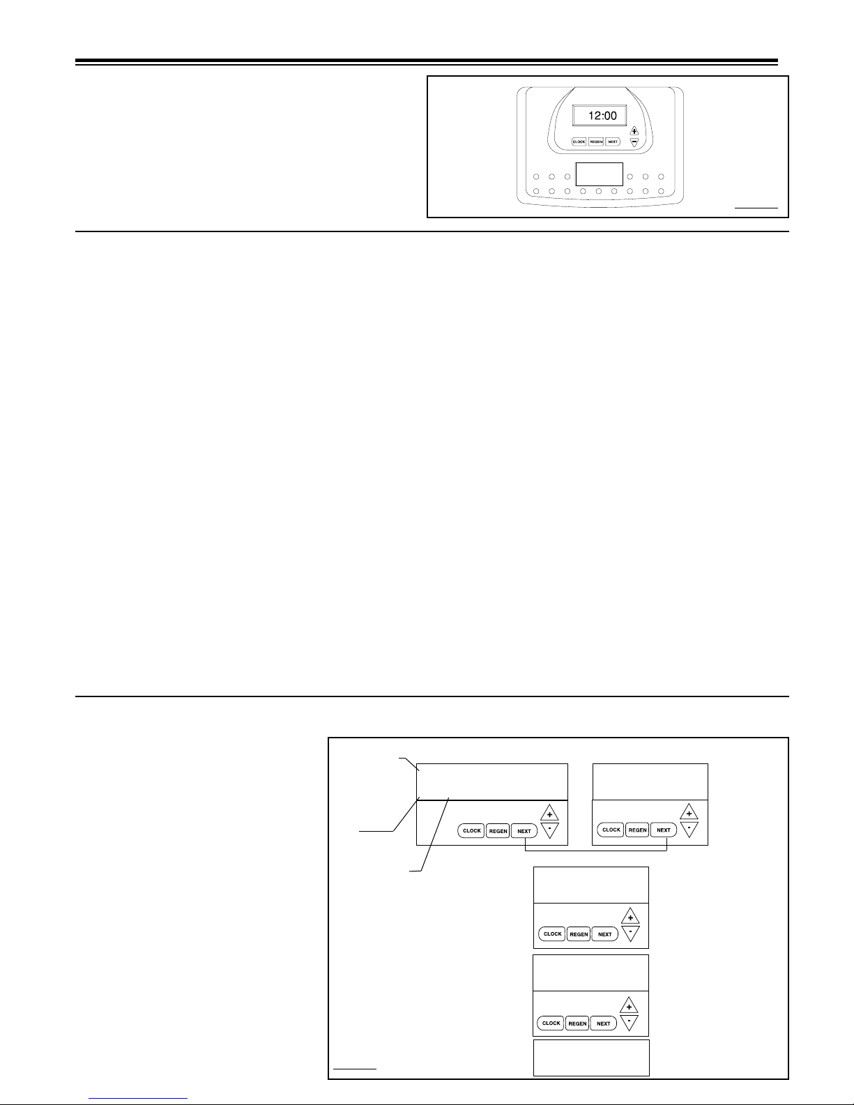
The display panel (see Figure 7) consists of the LCD display
and ve push buttons which are used in displaying and programming the water softener settings.
Figure 7
Initial Start Up
The initial start up will probably be done by the technician install-
ing the softener system. If not, the following instructions will step
through the process.
1. Complete all plumbing connections: inlet, outlet, drain line
and brine line. Do not add salt at this time.
2. Place the bypass valve in the bypass position. (See gure
3 page 5) Turn on the main water supply. Open a cold soft
water faucet to ush the piping of any air and/or foreign
material. Run until the water is clear.
3. Manually add 6 inches of water to the brine tank.
4. Now plug the transformer into a 110-volt receptacle. (Be
certain the outlet is uninterrupted.) Within 5 seconds the
control will automatically align itself into the softening mode
and display will automatically show time of day. (Figure
8, page 7).
5. Set the time of day by pushing set clock button (gure 9,
page 8) and using and buttons.
6. Push REGEN button and hold it down for 3 seconds.
The system will advance to the "First" position. (Note:
Depending on how the system is programmed, it could
read backwash, rinse, brine or ll). If "First" position is not
"Rinse", push REGEN button to advance to next position.
Continue until "Rinse" shows in lower right hand corner of
display. Slowly place the bypass valve into the "diagnostic
mode" (see gure 4, page 4). Run water to drain until it
runs clear. Return the bypass valve to the bypass position
(see gure 3, page 4). Push REGEN button to advance
to next position. Continue until unit is back to softening
mode with time of day displayed. Repeat this process for
second tank.
7. Once again, push REGEN button and hold down for 3
seconds. The system will advance to the "First" position. If
"First" position is not "Backwash", push REGEN button to advance
to next position. Continue until "Backwash" shows in the lower
center portion of display. Slowly place the bypass valve into the
"diagnostic mode" 1/2 way. (see gure 4, page 4). Allow water
to slowly ll the brine tank. When a solid stream of water starts
coming out of the drain line, open the bypass inlet valve all the
way and allow water to run out the drain until water clears. Slowly
place the bypass into the "normal operation" mode by opening the
outlet side of the bypass valve (gure 2, page 4).
8. Push REGEN button to advance to Brine dN position. Loosen
the brine line from the top of the safety brine valve in brine tank.
Place nger over the end of the elbow to check for suction. If
no suction, see trouble-shooting guide (#10, page 17). If proper
suction, reattach brine line and allow it to draw water down to the
bottom of the air check (see gure 6b, page 5).
9. Push REGEN button to advance to "Rinse" position. Rinse until
water again runs clear at the drain.
10. Push REGEN button to advance to softening mode with time of
day displayed.
Repeat steps 6–10 for the second tank.
11. When completed, display will show time of day. Pushing next
button can change display from time of day to online tank/ow
rate or gallons capacity remaining.
12. Add salt to brine tank (if provided by installer) or instruct end user
of type and quantity of salt to add. If utilizing brine reclaim, manually add full volume of water to brine tank for rst regeneration.
13. Proceed to Installer Settings on Page 7.
Note: These instructions are based on Hellenbrand Factory Default
Cycle Sequence Settings. If factory settings are changed, you may
need to adjust the number of times pushing REGEN to get to the
proper program cycle.
General Operation
When the system is operating, one of three
displays may be shown (four if the Salt Monitor
Option is activated). The rst display is current
time of day. The second display shows the
tank in service on the left (A is the tank with
control valve and b is the tank with the in/out
head) and the current ow rate in gallons per
minute. The third display is the gallons capacity
remaining. The user can scroll between the
displays by pushing NEXT. Note: If the Salt
Monitor Option is activated, a fourth display
(Salt Fill) will be displayed prior to the gallons
capacity remaining.
When water is being treated (i.e. water is owing through the system) the word "softening"
ashes on the left side of display. If the display
is in the tank in service/current ow rate, the
word "softening" ashes on the left side of the
display and the actual ow rate is displayed
on the right side of the display.
6
USER DISPLAYS/SETTINGS
REGEN TODAY
ashes in upper left
corner of display
between rotating display when REGEN
button pushed once.
GPM
Flashes when the
turbine is rotating.
TANK IN SERVICE
User screens will continuously scroll, switching
views every 3 seconds. If the screens are manually scrolled, this screen will remain constant for
5 minutes then continue to scroll. The conditional
screens will take precedence over the scrolling
and the conditional conditions will apply.
To manually reduce capacity, press down button
while capacity remaining or days to a regen is
displayed.
Figure 8
REGEN TODAY
GPM
NORMAL OPERATION SCREENS
CAPACITY REMAINING
b
GAL
650
TIME OF DAY
A
FLOW RATE
A
DEALER NAME
DEALER PHONE NUMBER
DAYS TO A REGEN
b
➔
➔
➔
6:35
➔
6.8
USER DISPLAY 1
Typical user
6
PM
USER DISPLAY 2
Displays current time.
GPM
USER DISPLAY 3
Displays present ow
rate.
May display if service is required.
display. Shows
capacity or days
remaining before a
regeneration.
SET TIME OF DAY
➔
SET TIME
SET TIME
6:35
➔
6:35
➔
PM
PM
STEP 1
STEP 2
STEP 3
STEP 1
= Up Arrow = Down Arrow
Step 1 - Press CLOCK.
Step 2 - Current Time (hour): Set the hour of the day using or buttons. AM/PM
toggles after 12. Press NEXT to go to step 3.
Step 3 - Current Time (minutes): Set the minutes of day using or buttons. Press
NEXT to exit Set Clock. Press REGEN to return to previous step.
Power Loss - Lithium battery on circuit board provides up to 2 years of time clock backup
during power outages. If the power is out when battery is depleted, only time of day needs
to be reset, all other values are stored in non-volatile memory. When time of day is ashing, replace lithium coin type 2032 battery.
Do not forget to reset for daylight savings time.
Figure 9
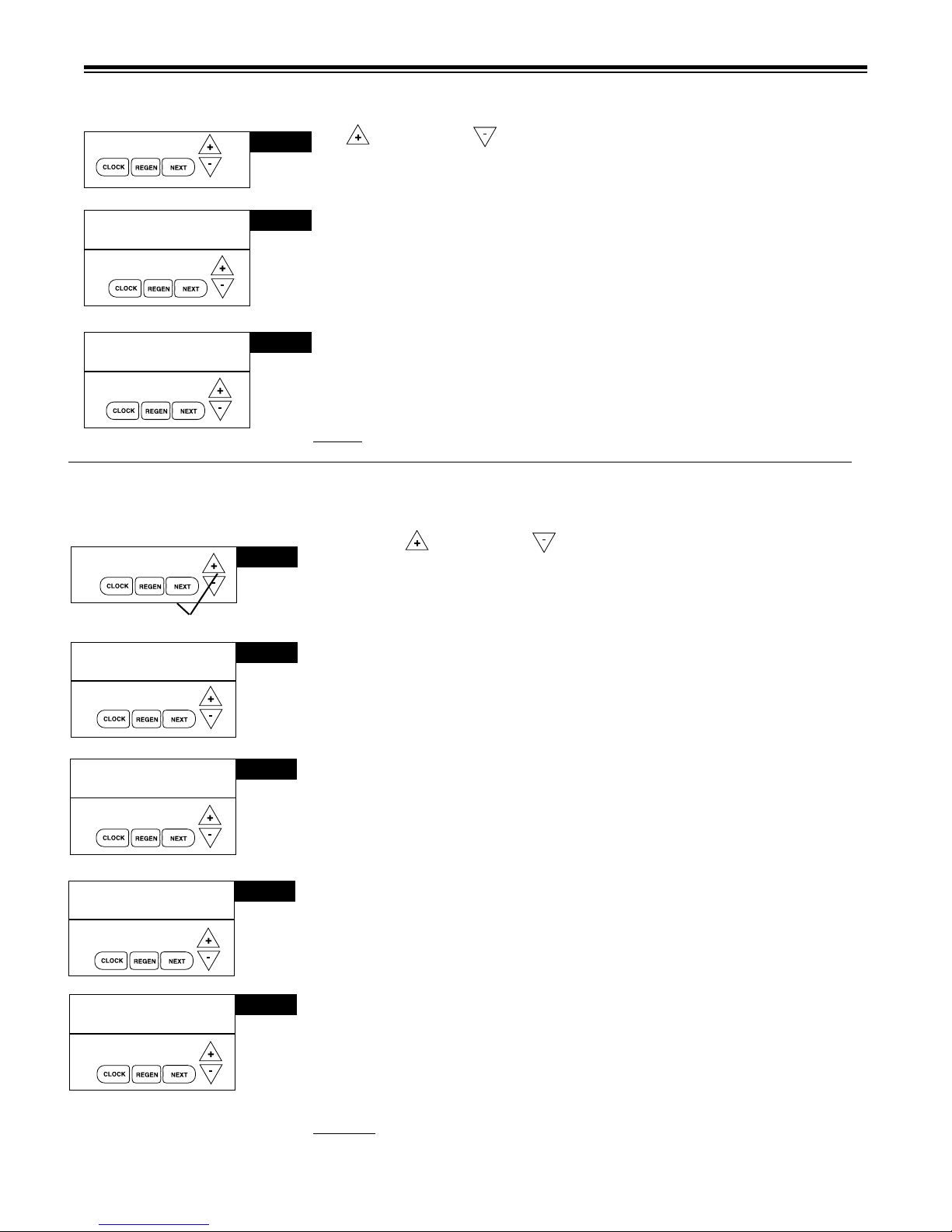
INSTALLER DISPLAYS/SETTINGS
= Up Arrow = Down Arrow
Step 1 - Press NEXT and simultaneously for 3 seconds.
SET HARDNESS
SET
REGEN DAY
SET TIME
REGEN
SET TIME
REGEN
2:00
2:00
➔
➔
➔
➔
➔
20
14
AM
AM
STEP 2
STEP 3
STEP 4
STEP 5
Step 2 - Hardness: Set the amount of total compensated hardness in grains (hard-
ness as calcium carbonate) per gallon using or buttons. The factory setting is 20
with value ranges from 1 to 150 in 1 grain increments. Note: The grains per gallon
should be increased if soluble iron needs to be reduced. Add 3 grains of hardness
for each ppm of iron present. If this display shows nA -, then system is set-up in “lter”
mode or "AUTO" is not selected in softener system setup. (See page 27). Press
NEXT to go to Step 3. Press REGEN to exit Installer Displays/Settings.
Step 3 - Day Override: This sets the number of days between regenerations. If
value set to “oFF” regeneration initiation is based solely on gallons used. If value is
set as a number (allowable range from 1 to 28) a regeneration initiation will be called
for on that day even if sufcient number of gallons were not used to call for a regeneration. Set Day Override using or buttons: Factory setting is 14 days.
• number of days between regeneration (1 to 28); or
• “oFF”
See gure 12a & b, page 10-11, for more detail on softener setup. Press NEXT to go
to step 4. Press REGEN to return to previous step.
Step 4 - Regeneration Time (hour): Set the hour of day for regeneration using or
buttons. AM/PM toggles after 12. The factory setting time is 2:00 a.m. This display
will show “REGEN” on 0 GAL if system is set for immediate regeneration. See page
27. Press NEXT to go to step 5. Press REGEN to return to previous step.
Note: When installing this unit as part of a multi unit parallel system the
day must be adjusted to prevent multiple units from regenerating
Step 5 - Regeneration Time (minutes): Set the minutes of day for regeneration using
or buttons. This display will not be shown if system is set for immediate regeneration. Press NEXT to exit Installer Displays/Settings. Press REGEN to return to
previous step.
at the same time.
regen time of
RETURN TO
NORMAL MODE
7
Figure 10a
Manual Regeneration
Sometimes there is a need to regenerate the system, sooner than when the system calls for it, usually referred to as manual regeneration. There may be a period of heavy water usage because of
guests or a heavy laundry day.
To initiate a manual regeneration at the preset delayed regeneration time, press and release
“REGEN”. The words “REGEN TODAY” will ash on the display to indicate that the system
will regenerate at the preset delayed regeneration time. If you pressed the “REGEN” button
in error, pressing the button again will cancel the request.
To initiate a manual regeneration immediately, press and hold the “REGEN” button for ve
seconds. The system will begin to regenerate immediately. The request cannot be cancelled. You
must cycle all the way through the cycles to make it stop. PLEASE NOTE: This will reset the meter.
Note: If the salt tank does not contain salt, ll with salt and wait at least two hours before
regenerating.
CAPACITY REMAINING
REGEN
TODAY
(shows time remaining in regen step
is 8 minutes, 22 seconds)
320
Regeneration Step
GAL
Regeneration Mode
Typically a system is set to regenerate at a time of low water usage. An example of a time with low
water usage is when the household is asleep. If there is a demand for water when the system is
regenerating, untreated water will be supplied.
When the system begins to regenerate, the display will change to include information about the step
of the regeneration process and the time remaining for that step to be completed. The system runs
through the steps automatically and will reset itself to provide treated water when the regeneration
has been completed.
REGEN
8:22
BACKWASH
Figure 11
CYCLE TIME ADJUSTMENTS
Normally it is not recommended to adjust the lengths of the cycle times. However, certain water conditions may
dictate adjustments. This should only be done from the recommendation of a water conditioning professional.
The following chart shows the upper and lower limits of each cycle.
Cycle Options Units Lower/Upper Limit Factory Setting
Fill Lbs. 0.1 to 1200 See Page 26
Softening (Service) Minutes 1 to 480 120
Backwash Minutes 1 to 120 8
Brine Minutes 1 to 180 60
Backwash Minutes 1 to 120 8
Rinse Minutes 1 to 120 4
STEP 1S
➔
SET
SOFTENING
STEP 2S
➔
SET
1 10.0
FILL
LBS
STEP 3S
➔
8
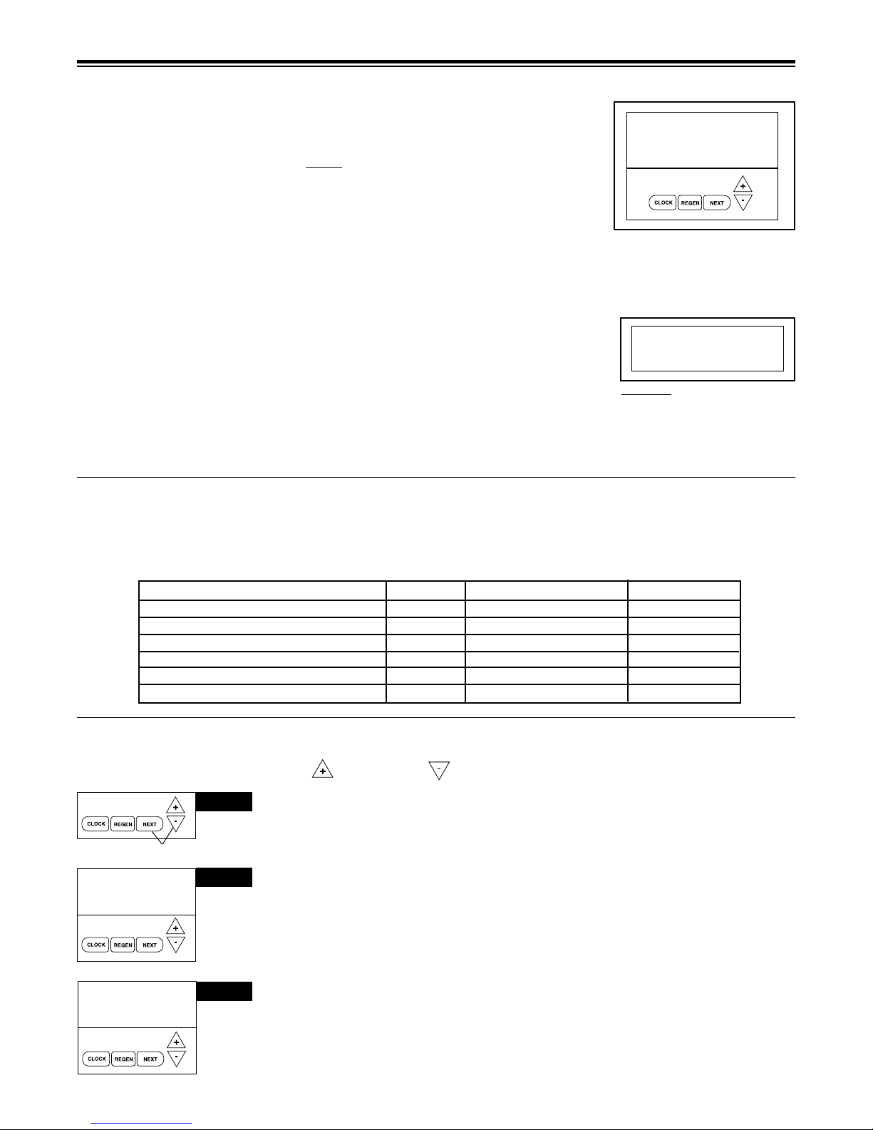
SOFTENER SETUP
= Up Arrow = Down Arrow
STEP 1S – Press NEXT and simultaneously for 3 seconds. If screen in Step 2S does
not appear in 5 seconds the lock on the valve is activated.
STEP 2S – Select between softening or ltering. A ashing "SOFTENING" or "FILTER-
ING" will appear. Choose SOFTENING using or button. Factory setting is Soften-
ing. Press NEXT to go to Step 3S. Press REGEN to exit Softener System Setup.
STEP 3S – Select the time for the rst cycle (which in this example is FILL, setting is
changed by lbs. of salt entered) using the or button. Factory setting is Medium
Salting, See page 26. Press NEXT to go to Step 4S. Press REGEN to return to previous
step. If 2.0" valve selected, ll cycle is programmed by minutes.
SET
SOFTENING
2 120
➔
MIN
STEP 4S
STEP 4 S – Select the time for the second cycle (which in this example is SOFTENING)
using or button. Press NEXT to go to Step 5S. Press REGEN to return to the previous
step.
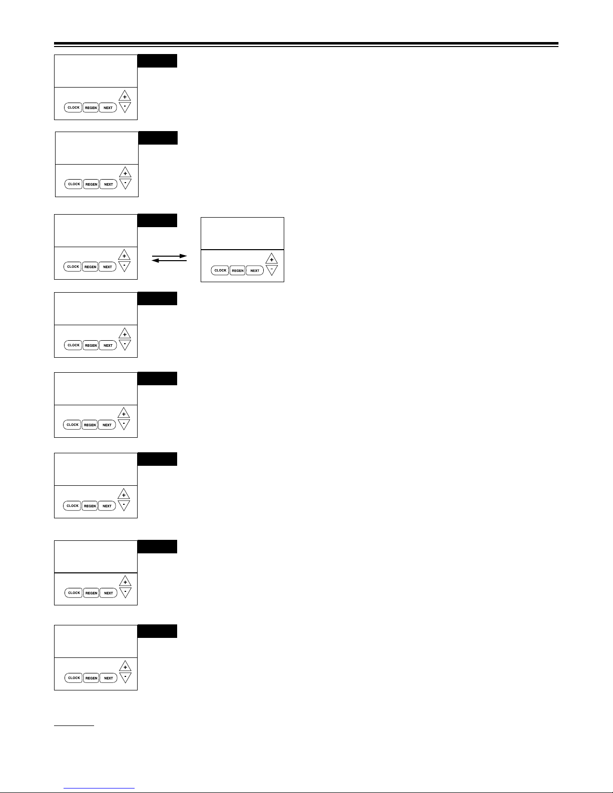
SET
BACKWASH
SET
4 dn
SET
BACKWASH
SET
3 8
➔
BRINE
➔ ➔
5 8
6 4
RINSE
MIN
MIN
MIN
MIN
STEP 5S
STEP 6S
STEP 7S
STEP 8S
STEP 5 S – Select the time for the third cycle (which in this example is BACKWASH) using
the or button. Press NEXT to go to Step 6S. Press REGEN to return to the previous
step.
SET
4 60
BRINE
STEP 8 S – Select the time for the sixth cycle (which in this example is RINSE) using the
or button. Press NEXT to go to Step 9S. Press REGEN to return to the previous step.
STEP 6 S – Select the time for the fourth cycle (which in this
MIN
example is dn BRINE) using the or button. Press NEXT to go
to Step 7S. Press REGEN to return to the previous step.
STEP 7 S – Select the time for the fth cycle (which in this
example
to Step 8S.
is BACKWASH) using the or button. Press NEXT to go
Press REGEN to return to the previous step.
9
CAPACITY
SET
REGEN
24.0
SET
NORMAL
SET
REGEN
AUTO
Figure 12a
➔
➔
FILL
➔
➔
x1000
GAL
STEP 9S
STEP 10S
STEP 11S
STEP 9 S - Set Grain Capacity using the or button. The ion exchange capacity is in
grains of hardness as calcium carbonate for the system based on the pounds of salt that will
be used. The allowable grains capacity range varies from 5,000 to 1,500,000 grains. The
increment increase is 500 for the range from 5000 to 30,000; 1000 for the range of 30,000 to
100,000; and 5000 for the range of 200,000 to 1,500,000. Grains capacity is affected by the
ll time. The grains capacity for the selected lbs. salting should be conrmed by testing. The
capacity and hardness levels entered are used to automatically calculate reserve capacity
when gallon capacity is set to AUTO. Factory setting is the capacity of the softener at
medium salting. See Page 26. Press NEXT to go to Step 10S. Press REGEN to return to
previous step.
STEP 10 S – Select between proportional or normal brining. Use or buttons to se-
lect. Proportional brining is only available if congured as prell/upow softener or screen will
not appear. Proportional brining will divide the actual gallons used by calculated volumetric
capacity then multiply ll volume by this percentage. This option requires a functioning meter.
Factory Setting = Normal brining. Press NEXT to go to Step 11S. Press REGEN to return
to previous step.
STEP 11 S – Set Gallons Capacity using or button. If value is set to:
• “AUTO” gallon capacity will be automatically calculated and reserve capacity will be automatically estimated;
• “oFF” regeneration will be based solely on the day override set (see Installer Display/Settings Step 3 I, page 8 / proportional brining will not function if OFF selected); or
• as a number of gallons (allowable range 20 to 1,500,000) regeneration will be based on the
value specied.
Increment increase is 20 for the range 20 to 2000, 100 for the range of 2000 to 10,000 and
500 for the range of 10,000 to 50,000 and 2000 for range of 50,000 to 1,500,000.
If “oFF” or a number is used, hardness cannot be set in Installer Displays/Settings Step 2 I,
page 8. See page 27 for more detail. Factory Setting is AUTO. Press NEXT to go to Step
12 S. Press REGEN to return to previous step.
 Loading...