

Page 1
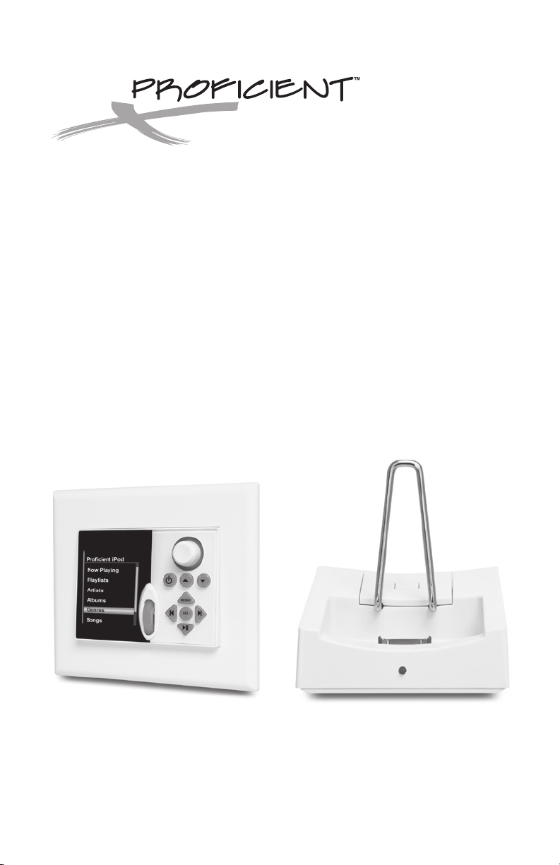
Audio Systems
The Source
Installation & Programming Guide
Page 2
PORTABLE CART
WARNING
SAFETY INSTRUCTIONS
RISK OF ELECTRIC SHOCK
DO NOT OPEN
CAUTION
CAUTION: To reduce the risk of electric shock,
do not remove cover, (or back).
No user serviceable parts inside.
Refer servicing to qualied service personnel.
The lightning ash with arrowhead symbol, when in an equilateral triangle,
is intended to alert the user to the presence of in-insulated
"dangerous voltage" within the product's enclosure that may be of
sucient magnitude to constitute a risk of electric shock to persons.
The exclamation point, within an equilateral triangle, is intended to alert
the user to the presence of important operating and maintenance (servicing) instructions in the literature accompanying
the appliance.
APPLICABLE FOR USA, CANADA OR
WHERE APPROVED FOR USAGE
CAUTION: TO PREVENT ELECTRIC SHOCK,
MATCH WIDE BLADE PLUG TO WIDE SLOT,
ATTENTION: POUR EVITIER LES CHOCS
ELECTRIQUES, INTRODUIRE LA LAME LA PLUS LARGE
CORRESPONDANTE DE LA PRISE ET POUSSER JUSQU
Read all of these instructions before operating and save instructions for later use.
1. Read Instructions – All the safety and operating instructions should be read before the appliance is operated.
2. Retain Instructions – The safety and operating instructions should be retained for future reference.
3. Heed Warnings – All warnings on the appliance and in the instructions should be adhered to.
4. Follow Instructions – All operating and use instruc tions should be followed.
5. Water and Moisture – The appliance should not be used near water – for example, near a bathtub, washbowl, kitchen sink, laundry tub, in a wet basement
or near a swimming pool.
6. Carts and Stands – The appliance should be used only with a cart or stand that is recommended by the manufacturer. An appliance and cart combination
should be moved with care. Quick stops, excessive force, and uneven surfaces may cause the appliance and cart combination to overturn.
INSERT FULLY
DE LA FICHE DANS LA BORNE
AU FOND
7. Wall or Ceiling Mounting – The appliance should be mounted to a wall or ceiling only as recommended by the manufacturer.
8. Ventilation – The appliance should be situated so that its location or position does not interfere with its proper ventilation. For example, the appliance
should not be situated on a bed, sofa, rug, or similar surface that may block the ventilation openings; or, placed in a built-in installation, such as a bookcase
or cabinet that may impede the ow of air through the ventilation openings.
9. Heat – The appliance should be situated away from heat sources such as radiators, heat registers, stoves, or other appliances (including ampliers) that
produce heat.
10. Power Sources – The appliance should be connected to a power supply only of the type described in the operating instructions or as marked on the appliance.
11. Grounding or Polarization – Precautions should be taken so that the grounding or polarization means of an appliance is not defeated.
12. Power-Cord Protection – Power-supply cords should be routed so that they are not likely to be walked on or pinched by items placed upon or against them,
paying particular attention to cords at plugs, convenience receptacles, and at the point where they exit from the appliance.
13. Cleaning – The appliance should be cleaned only as recommended by the manufacturer.
14. Power Lines – An outdoor antenna should be located away from the power lines.
15. Nonuse Periods – The power cord of the appliance should be unplugged from the outlet when left unused for a long period of time.
16. Object and Liquid Entry – Care should be taken so that objects do not fall and liquids are not spilled into the enclosure through openings.
17. Damage Requiring Service – The appliance should be ser viced by qualied service personnel when:
A. The power-supply cord or the plug has been damage; or
B. Objects have fallen, or liquid has spilled into the appliance; or
C. The appliance has been exposed to rain; or
D. The appliance does not appear to operate normally or exhibits a marked change in performance; or
E. The appliance has been dropped or the enclosure damaged.
18. Servicing – The user should not attempt to service the appliance beyond that described in the operating instructions. All other servicing should be referred
to qualied service personnel.
2
Page 3

TABLE OF CONTENTS
INTRODUCTION ..................................................................................................................................................................4
What’s Included .........................................................................................................................................................5
Accessories (Not Included) ....................................................................................................................................5
What You Will Need ..................................................................................................................................................5
THE SOURCE KEYPAD FEATURES ..................................................................................................................................6
Front Panel ...................................................................................................................................................................6
Rear Panel ....................................................................................................................................................................7
THE SOURCE DOCK ADAPTER FEATURES .................................................................................................................8
THE SOURCE DOCK FEATURES ......................................................................................................................................9
TYPICAL SYSTEM .............................................................................................................................................................11
WIRING ................................................................................................................................................................................. 12
The Source Keypad ................................................................................................................................................12
Speaker Mute Relay ...............................................................................................................................................12
The Source Dock Adapter ...................................................................................................................................12
The Source Dock ..................................................................................................................................................... 12
SOURCE KEYPAD HARD BUTTON CONFIGURATION .........................................................................................13
INSTALLATION ..................................................................................................................................................................15
The Source Keypad ................................................................................................................................................15
The Source Dock Adapter ...................................................................................................................................17
CONNECTIONS .................................................................................................................................................................18
The Source Keypad ................................................................................................................................................18
The Source Dock and Dock Adapter (Single) ...............................................................................................20
The Source Dock and Dock Adapter (Ganged)............................................................................................21
PROGRAMMING ...............................................................................................................................................................22
Programming with Proficient Editor ...............................................................................................................22
Download Proficient Editor ................................................................................................................................22
Quick Start for Simple Source Proficient Editor Programming ..............................................................22
Adding the Source Dock & Source Dock Adapter to an Existing Project ........................................... 24
Adding a Source Keypad to an Existing M4/M6 Project...........................................................................27
Programming the Virtual Source Keypad ......................................................................................................31
Programming Control of Sources .....................................................................................................................34
Programming Hard Keys......................................................................................................................................34
Programming Virtual Buttons ............................................................................................................................35
OPERATING THE SOURCE KEYPAD............................................................................................................................37
Power On ................................................................................................................................................................... 37
Power Off ..................................................................................................................................................................37
Adjust Volume .........................................................................................................................................................38
Mute ............................................................................................................................................................................38
Source Keypad Control—CD, Servers, SIRIUS, XM, etc. ............................................................................ 38
Source Keypad Control—M6 Tuners. .............................................................................................................. 39
Source Keypad Control—iPod. ..........................................................................................................................39
Party Mode ...............................................................................................................................................................40
Zone Settings (Treble and Bass) .......................................................................................................................40
Keypad Settings ......................................................................................................................................................40
Keypad Reset ...........................................................................................................................................................41
Specifications ..................................................................................................................................................................... 42
Limited 2-Year Warranty ................................................................................................................................................. 43
3
Page 4

INTRODUCTION
The Source Keypad creates the ultimate media control experience by providing
real-time system status, menu-driven control options and source metadata with its
vertically mounted high-resolution color LCD. Menu options include system source
selection, M6 Internal Tuner Presets with frequency, iPod® menus and metadata as
well as a variety of Keypad setup options.
The real beauty of the Source Keypad is that it is so easy to operate. A Scroll Wheel
and Select Button allow navigation through and selection of the displayed menu
options. Once a source has been selected, 7 back-lit programmable hard keys
provide source control and on-screen menu navigation for sources such as CD
players, media servers, etc. These buttons have all of the programmability expected
of a Proficient Keypad, with each button being able to initiate single IR commands,
RS232 commands, Proficient M4 & M6 Internal Commands and macros in each of up
to three tiers of functionality.
Volume is controlled with a back-lit control knob that features a series of LEDs that
give a visual indication of the volume setting.
The Source Keypad is designed specifically for use with the Proficient M4 and M6.
They can be mixed and matched with Proficient PMK Keypads and run on the same
CAT5 wire used for PMKs. The Source Keypad includes a J-box Mounting Bracket that
allows installation in most standard 2-gang low-voltage new construction and some
retro-fit electrical boxes. This design philosophy allows The Source Keypads to be
retrofit to upgrade existing M4 & M6 installations.
Though parts of this manual cover The Source Dock and The Source Dock Adapter
for incorporating iPod and additional sources, the Source Keypad does not require
these components for installation and operation. The Source Keypad can be
installed without the Source Dock and Source Dock Adapter and used purely as
an upgrade to PMKs in M4 & M6 Systems. The Source Keypad is programmed with
Proficient Editor Programming Software and follows procedures similar to those
used with PMK Keypads. All M4 & M6 System commands, IR Library commands and
RS232 commands previously saved in Proficient Editor can be used to program the
Source Keypad.
4
Page 5

INTRODUCTION
What's Included with The Source Keypad
1 – Source Keypad (White or Black)
1 – Source Keypad Mounting Bracket
1 – Source Keypad White Bezel (White Version Only)
1 -–Set of Source Keypad Black, Bone & Almond Bezels (Black Version Only)
1 – Bag of Replacement Buttons
1 – Wire Retainer
What's Included with The Source Dock & Dock Adapter
1 – Source Dock
1 – Source Dock Adapter
1 – 10' Stereo Mini to RCA Interconnect Cable
1 – 6" Ribbon Cable
Accessories (Not Included)
1 - The Source Power Supply. 24V DC 2.5 Amp Power Supply for the Source Dock
Adapter. (One power supply supports up to 6 ‘ganged’ Source Dock Adapters.)
What You Will Need
• 110 Punch-Down Tool
• RJ-45 Crimp Tool
• RJ-45 Plugs
• Screw Driver
• Wire Cutters
5
Page 6
THE SOURCE KEYPAD FEATURES
SEL
MENU
45678
1 2 3
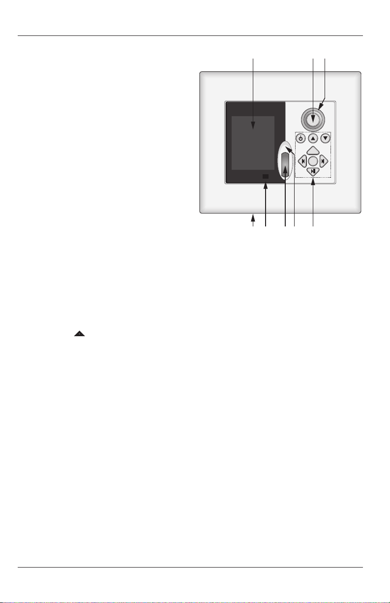
FRONT PANEL (Figure 1)
1. HIGH RESOLUTION COLOR LCD - High
Resolution color LCD displays ‘Virtual
Buttons’ for source selection, menu
navigation, control, metadata from iPods,
M6 Tuner Presets and The Source Keypad
Setup Menu.
2. VOLUME CONTROL KNOB - Volume
control knob adjusts volume when
turned, mutes the local zone speakers
when pushed and executes a keypad
reset when pressed and held for 5
seconds. The knob can be programmed
for any function, but should typically be
programmed for volume and mute.
3. VOLUME LEVEL LEDs - 8 blue LEDs to
provide visual conrmation of volume
setting.
4. CONFIGURABLE HARD KEYS - 7 back-lit programmable and congurable hard keys
allow control of source components. These keys are programmed using Procient Editor
Programming Software. Each keypad includes a variety of additional keycaps for added
exibility.
Note: The 5 or “Menu” button is not programmable. The Menu button provides
navigation to return the display back to the Main Menu for all supported metadata
devices. When using The Source Dock, the Menu Button functions the same as an "iPod
Menu Button" when an iPod has been selected as a source (while navigating through
the iPod menus, press and hold the Menu Button to return to The Source Keypad Main
Menu.) Also, when navigating through iPod menus, the arrow up & arrow down buttons
to the right of the power button work as scan up, scan down when iPod menus are
lengthy such as song, album & artist list.
The Source Keypad Front Panel
Figure 1
5. CLICK BUTTON - The cosmetic trim surrounding the Scroll Wheel is actually a function
select key. When a source, menu item or function has been highlighted on the LCD with
the Scroll Wheel, a press of the Click Button will select the source or menu item or initiate
an associated command. This button is not programmable.
6. SCROLL WHEEL - Provides easy and intuitive navigation of menus and ‘Virtual Buttons’
displayed on the LCD. This button is not programmable.
7. IR SENSOR - The Source Keypad includes Procient’s exclusive ALR (Ambient Light
Restrictor) IR Receiver. The IR receiver allows use of a handheld remote for control of the
system and IR controlled source components.
6
Page 7
THE SOURCE KEYPAD FEATURES
IR
IR
+12
+12
GND
GND
485 A
485B
0
1
2
3
4
5
6
7
8
9
A
B
C
D
E
F
+ RELAY
- RELAY
9 12 11 9
1210
1414
13
IR
IR
+12
+12
GND
GND
485A
485B
Made in China
The Source Keypad
8. KEYPAD BEZEL - The keypad bezel is a screwless trim plate made of a pliable material that
conforms to the surrounding wall contour. The back of the bezel has form tting tabs that
friction t to The Source Keypad Mounting Bracket to provide a clean nished look.
Figure 2 The Source Keypad Rear Panel
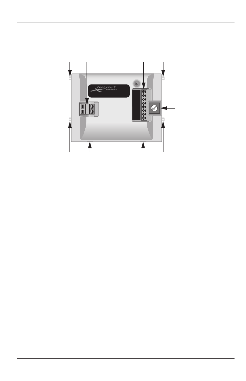
REAR PANEL (Figure 2)
9. KEYPAD SET TABS - Fit into the upper Mounting Bracket Tab Slots to secure the keypad
to the bracket.
10. KEYPAD ANGLE TABS - Fits into the channeled lower Mounting Bracket Tab Slots to
allow ush installation (at to wall surface) or with the lower portion of the keypad
sloping away from the wall at about a 15° angle. The angle mount creates a special
cosmetic appeal and provides an improved LCD viewing angle.
11. KEYPAD PUNCHDOWN BLOCK - 110 style punchdown terminal connects to the Zone
Keypad RJ45 jack on a Procient M4 or M6.
12. SPEAKER RELAY MUTE TERMINAL - Connects to a Procient Relay Muting Module for
individual room mute when using multi-channel ampliers for subzone expansion.
13. ADDRESS SWITCH - Unique addresses are not required zone-to-zone (One keypad per
zone). However, a unique address must be set for each Source Keypad when connected on
a common bus within a single zone. The switch provides up to 16 addresses (0 to F). The
default address for the Source Keypad is “A”.
14. FACEPLATE RELEASE TABS - Carefully push these recessed tabs to remove the Source
Keypad faceplate to change keycaps. It is typically only necessary to press the tabs on
the bottom of the keypad and then carefully pull the bottom of the faceplate away
from The Source Keypad body.
7
Page 8
16
16
15
15
15
17
THE SOURCE DOCK ADAPTER FEATURES
Line Out
Expansion
Aux. Input
Source Dock
24V DC
18
19
20
21
22
23
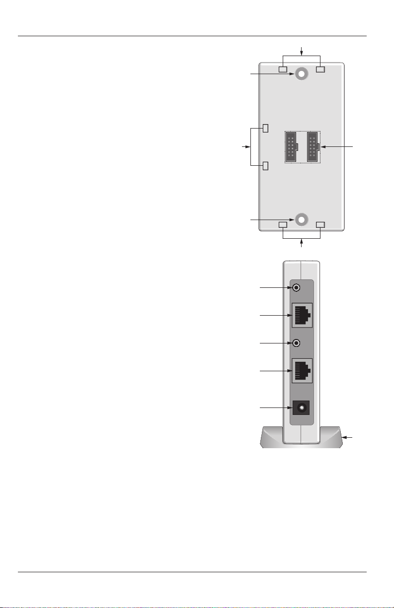
THE SOURCE DOCK ADAPTER (Figure 3)
15. ADAPTER BASE CLIP LOCKS - These indents lock
the Source Dock Adapter Base to the Dock Adapter
for shelf top or wall mount installation.
16. WALL MOUNT SCREW HOLES - These holes allow
The Source Dock Adapter to be mounted at
against a wall or cabinet side.
17. 12 PIN INTERCONNECT – This connection via
ribbon cable (included) creates a power, metadata
and control bus that allows ganging of up to six
Source Dock Adapters.
18. LINE OUT - 3.5mm mini jack outputs stereo line
level audio. Connects to M4 or M6 Source Input
via the included 10' stereo mini-plug to RCA
interconnect cable. When ganging multiple Dock
Adapters, each Dock Adapter must be connected to
a dedicated Source Input on the M4 or M6.
19. EXPANSION PORT - RJ45 Jack connects to the
Expansion Port on the M4 or M6 Rear Panel to Rx/Tx
control and metadata between the M4 or M6 and
the Source Dock Adapter.
20. AUX INPUT - 3.5mm mini jack provides a stereo
line level input for an additional source. This could
be anything from a CD Changer to an XM or Sirius
Tuner or music server, allowing up to 12 Sources
on an M4 or 14 Sources on an M6 (including onboard tuners). Switching to and controlling the
sources connected to this input must be congured
during setup in Procient Editor. Only the Source
Keypads have access to and control of the devices
connected to the Aux Inputs. PMKs do not have
access to or control of these devices.
21. SOURCE DOCK TERMINAL - RJ45 jack connects
The Source Dock Adapter Features
Figure 3
to the Adapter Port on a Source Dock via CAT5.
This connection provides power and control to
the iPod/Dock and receives digital audio data and metadata from a connected iPod.
22. 24V DC - 2.1mm coaxial jack connects to a Procient Source Power Supply (Required/Not
included). When ganging Adapters, one will power up to six Source Dock Adapters.
23. ADAPTER BASE - Attaches to the Dock Adapter for shelf top or wall mount installation.
8
Page 9
THE SOURCE DOCK FEATURES
12V DC 1 AMP Adapter Port Aux. Input USB
24
25 26 27 28
24
29 30 31
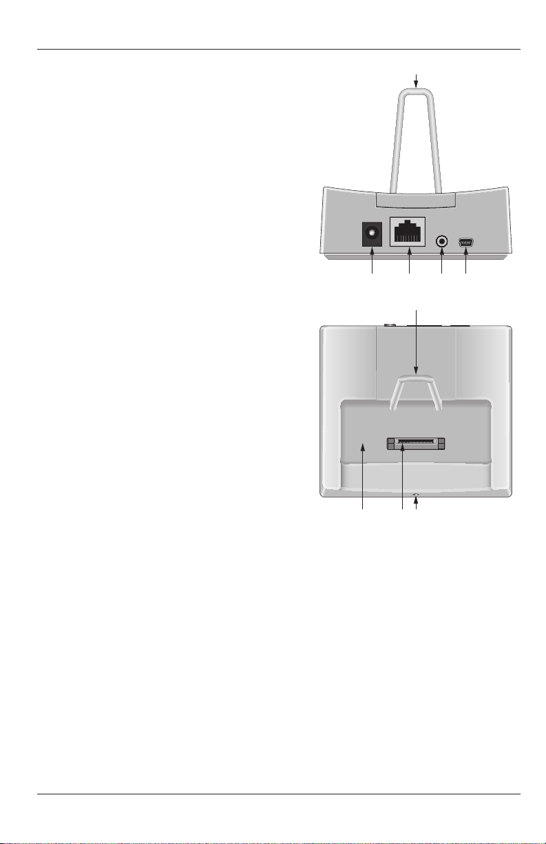
THE SOURCE DOCK (Figure 4)
24. iPOD SUPPORT BRACKET - Movable bracket
provides support for most iPod models to
prevent damage to the iPod Connectors.
25. 12V DC - 2.1mm coaxial jack. The Source
Dock is powered directly from The Source
Dock Adapter in applications where the Dock
is less than 250' from the Adapter. For wire
runs over 250', the Dock can be up to 500' from
the Adapter with a Procient IR Power Supply-
1.2A, connected directly to the Dock.
26. ADAPTER PORT - RJ45 jack connects to the
Source Dock Terminal on the Source Dock
Adapter via CAT5. This connection provides
power and control to the iPod/Dock and
sends digital audio and metadata from the
Dock to the Dock Adapter.
27. AUX INPUT - 3.5mm mini jack provides
a stereo line level input for an additional
source. This could be anything from a CD
Changer to an XM or Sirius Tuner or music
server, allowing up to 12 Sources on an M4
or 14 Sources on an M6 (including on-board
tuners). This connection will allow the local
source audio to be played through the M4 or
M6 amplier and zone speakers. Switching
to and controlling the sources connected to
this input must be congured during setup in
Procient Editor.
Figure 4 The Source Dock Features
28. USB PORT - USB mini jack allows connection directly to a computer for downloading
content to an iPod seated in the Source Dock. Downloading content would follow
normal procedures. See iPod instructions for additional information.
29. iPod WELL - This opening in the Dock is designed to accommodate most iPod models.
Connect the iPod to the iPod Connector, and slide the iPod Support Bracket forward to t
the particular iPod model.
30. iPod CONNECTOR - This multi-pin connector connects to the iPod Dock Connector on
the bottom of an iPod. Carefully push the iPod down on this connector to send power
and control to the iPod and have the iPod send digital audio and metadata to the system.
31. STATUS LED - LED illuminates blue when the Source Dock is receiving power.
9
Page 10
0
1
2
3
4
5
6
7
8
9
A
B
C
D
E
F
32
Made in China
The Source Dock
THE SOURCE DOCK FEATURES
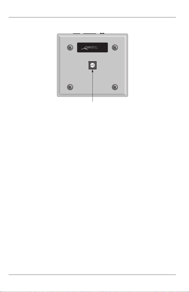
THE SOURCE DOCK (Figure 5)
Figure 5 The Source Dock Bottom
32. ADDRESS SWITCH - A unique address must be set for each Source Dock within a given
system. The switch provides up to 16 addresses (0 to F). The default address for the Source
Dock is “0”.
IMPORTANT NOTICE REGARDING ESD (Electrostatic Discharge): The Source Dock can be
susceptible to ESD. Under certain conditions when reaching for and just prior to touching
the Dock or the iPod connected to it, certain levels of ESD can cause The Source Dock to
temporarily lose its communication link with the M4 or M6. Typically no action is required by
the user to restore communication and normal operation. This notice pertains only to The
Source Dock. Please refer to iPod documentation or contact Apple for additional information
regarding iPod and ESD.
10
Page 11
TYPICAL SYSTEM
RS232
PHONE (PAGE IN)
DOORBELL / STATUS IN
1
2
CONTROL
PORT
FIRMWARE
UPGRADE
OFF ON
COMMON
IR OUT
LO
HI
STATUS OUT:
0 to +12V
120V 60Hz 1.8A~
FUSE: T5AL 250V
DATA I/O
CONTACT CLOSURE
EXPANSION PORTS
COMMON
M4
SOURCE1
LOOP
OUT
IR
LOOP
L R
INPUTS
SOURCE2
LOOP
OUT
IR
LOOP
L R
INPUTS
SOURCE3
LOOP
OUT
IR
LOOP
L R
INPUTS
SOURCE4
LOOP
OUT
IR
LOOP
L R
INPUTS
SOURCE5
LOOP
OUT
IR
LOOP
L R
INPUTS
SOURCE6
LOOP
OUT
IR
LOOP
L R
INPUTS
SPKRS
L
R
+
+ –
–
ZONE 4
L R
PRE-OUT
VC
NVC
KEYPAD
IR OUT
Riverside, CA. USA
Made in Taiwan
SPKRS
L
R
+
+ –
–
ZONE3
L R
PRE-OUT
VC
NVC
KEYPAD
IR OUT
SPKRS
L
R
+
+ –
–
ZONE2
L R
PRE-OUT
VC
NVC
KEYPAD
IR OUT
SPKRS
L
R
+
+ –
–
ZONE1
L R
PRE-OUT
VC
NVC
KEYPAD
IR OUT
Line Out
Expansion
Aux. Input
Source Dock
24V DC
Procient 12V DC
IR Power Supply-1.2A
(Use if exceeding 250' from Dock Adapter)
M4 or M6
THE SOURCE
DOCK ADAPTER
THE SOURCE DOCK THE SOURCE KEYPAD PMK KEYPAD
CAT5
CAT5
CAT5
Max 250'
16-14AWG
SPEAKER
WIRE
Stereo Mini to RCA Cable
Left Speaker Right Speaker Left Speaker Right Speaker
Playlists
Artists
Albums
Songs
Genres
Composers
>
>
>
>
>
>
Music
Podcasts >
SEL
MENU
DVD
MUTE
SAT
CD
PWR
BASS TREB
TNR
iPod
AUX
PLAY
ESC INFO
MENUGUIDE
SEL
CAT5
The Source
24V DC
Power Supply
To
M4 or M6
Source
Input
The Source Zone PMK Zone
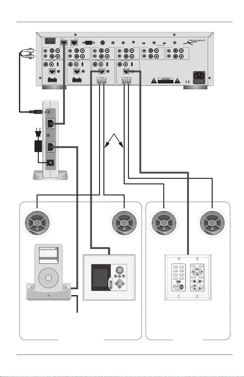
Figure 6 Typical System Wiring Diagram
11
Page 12

WIRING
The Source Keypad requires connection to a Procient M4 or M6 to operate. All system wiring
considerations for an M4 or M6 system should be followed as described in the M4 or M6 Quick
Start Guides. The information below will only detail those parts of an M4 or M6 System that
pertain to the wiring requirements for connecting the Source Keypad, the Source Dock and
The Source Dock.
Note: The following wires should be installed during system pre-wire. Other connections will
be made at the time of installation and are described in the “Connections” section.
THE SOURCE KEYPAD
CAT5 - Pull home-runs of CAT5 from each Source Keypad to the system head-end.
Maximum Length: 500'
Note: All eight conductors of the CAT5 must be connected for proper signal strength on
500' of cable.
SPEAKER MUTE RELAY
The Speaker Mute Relay is used when multiple rooms are grouped to one zone (i.e.
Master Bedroom and Master Bathroom). When used and programmed, only the speakers
matched to the keypad will turn on/o (i.e. turn on the bathroom keypad only, the
bathroom speakers will turn on).
The room speakers wire through the Speaker Mute Relay and a two conductor wire from
the Speaker Mute Relay to the PMK or The Source Keypad relay connections.
Standard Wire - Pull two-conductor 24AWG or heavier, stranded, non-shielded wire from
any Source Keypad location to where a Procient Speaker Mute Relay will be installed.
Maximum Length: 1000'
THE SOURCE DOCK ADAPTER
No pre-wire necessary. Locate with an M4 or M6 for Connections.
THE SOURCE DOCK
No pre-wire necessary if located with an M4 or M6. If in a a remote location (i.e. kitchen,
bedroom, living room, etc.), run 1 CAT5 from The Source Dock Adapter location to The
Source Dock location. If wire run is greater than 250', a Procient IR Power Supply 1.2A
will be required at The Source Dock location.
12
Page 13
SOURCE KEYPAD HARD BUTTON CONFIG
As received from the factory, the Source Keypad has a preinstalled set of buttons that match
the default button conguration in Procient Editor. This default may not match the system
being installed. The Source Keypad comes with a set of alternate buttons. The hard button
keycaps can be changed on the keypads and in Procient Editor to match the product being
installed. To change the hard button keycaps:
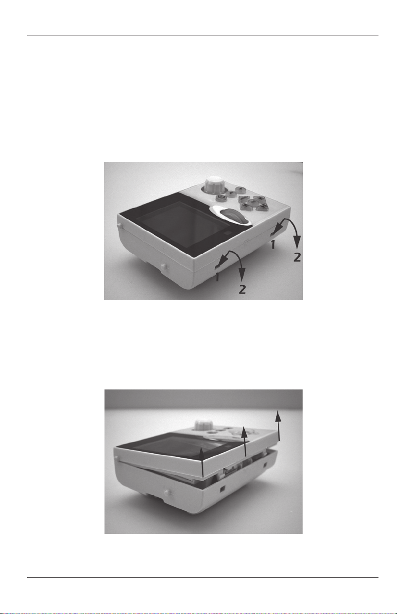
1. With the keypad disconnected from the system, carefully insert a small at head
screwdriver into the Faceplate Release Tabs Slots (1) as shown in Figure 7. With the
screwdriver inserted, slowly twist the screwdriver and pull down in the direction shown
(2) until the Faceplate Tabs release from the body.
Figure 7 Faceplate Release Tabs
2. With both tabs released, carefully pull the bottom of the faceplate up and away from
the keypad as shown in Figure 8 until it stops moving freely. Carefully pull the top of the
faceplate clear of the keypad to remove. Do not touch, pinch, poke or otherwise contact
the ex board circuit connected to the top of the LCD. Damage to the ex board will
disable the LCD.
Figure 8 Removing The Faceplate
13
Page 14
SOURCE KEYPAD HARD BUTTON CONFIG
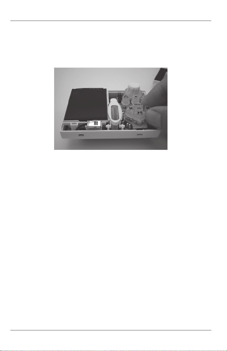
3. With the faceplate fully removed, the hard button keycaps can be changed. Carefully
pinch the top of the keycap and slowly pull it straight up and o the rubber membrane
as shown in Figure 9. Try not to pull the membrane o the green circuit board. If the
membrane does come loose, be sure to replace it to its normal position, seated at on
the green circuit board. If the membrane is not properly seated, the keycaps will not t
properly through the openings in the faceplate and the keypad will not function.
Figure 9 Changing Keycaps
4. Using the included alternate set of keycaps, make changes as needed.
5. With all keycaps in place, replace the faceplate in reverse process to Step 2. Carefully
align the top of the faceplate with the keypad body as they appear in Figure 8. Slowly
press the bottom of the faceplate until the keycaps begin to push through their
openings. Visually inspect the keycaps to conrm that they are properly centered in the
faceplate openings. With the keycaps in place, press the bottom corners of the faceplate
until it snaps into place.
6. Press all buttons to conrm free play.
14
Page 15
INSTALLATION
2-Gang
New Construction Box
SOURCE
Mounting Bracket
SOURCE
Keypad
SOURCE
Bezel
Bezel Tab Clips
Keypad Angle
Tab Slots
Keypad
Angle Tabs
Bezel Tabs
THE SOURCE KEYPAD
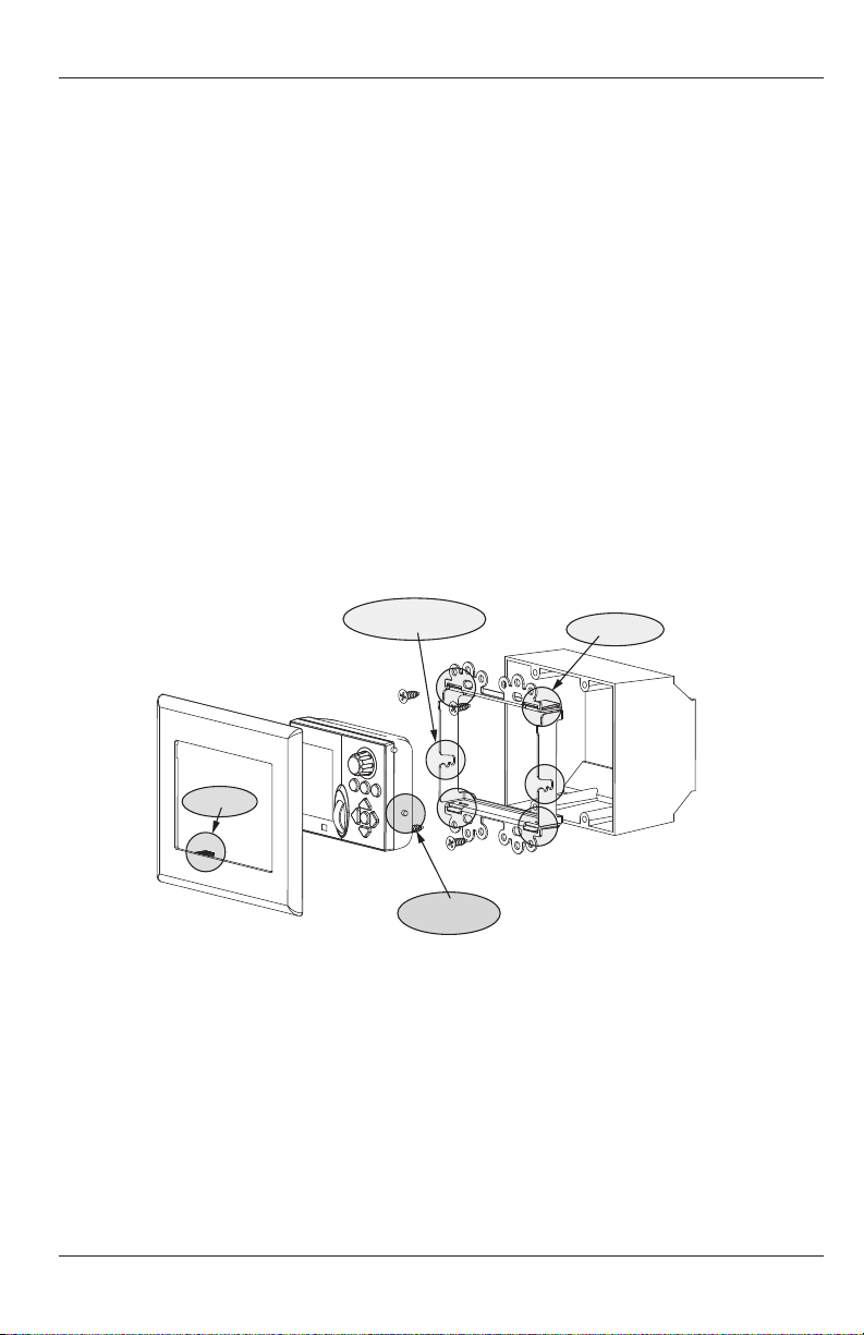
J-BOX (Figure 10)
Note: It is highly recommended that The Source Keypad be installed at a height of 56" on
center. This provides the best overall position for optimum LCD viewing angle. This should be
discussed with the homeowner prior to installation to avoid rework, should the homeowner
nd this undesirable.
New Construction
The Source Keypad should be mounted in a standard 2-gang new construction box whenever
possible. The keypad itself has a thin prole, but the Bezel Tabs and the Mounting Bracket
Bezel Tab Clips require some additional clearance. Some new construction and many retrot
boxes do not provide adequate clearance. Checking the t of an assembled keypad, (bezel,
keypad and mounting bracket), is recommended prior to installation of the J-boxes to avoid
problems after the wall board has been installed.
Retrot
Although use of retro boxes is not recommended, they can be used in some cases. If using
a retro box, it will probably be necessary to hone out part of the box to provide height and
depth clearance for the Mounting Bracket Bezel Tab Clips and Bezel Tabs. Do not modify the
clips or the tabs as this may adversely aect how well the bezel stays in place.
Figure 10 Mounting The Source Keypad
Mounting Bracket
The Source Keypad cannot be installed without the Mounting Bracket. The keypad is held in
place with the Keypad Locking Tabs and Keypad Angle Tabs. The Bracket should be mounted
to a standard 2-gang new construction box as shown in Figure 10. When installing the
Mounting Bracket, be sure the bracket is positioned as shown in Figure 10. The keypad cannot
be mounted if the bracket is upside down. If using a retro box, see the “Retrot” section
above. When necessary, though not recommended, the Mounting Bracket can be used
without a J-box. When installing a keypad without a J-box, be sure to use drywall anchors to
provide a more durable and secure mount for the bracket.
15
Page 16

INSTALLATION
THE SOURCE KEYPAD
With the Mounting Bracket installed, the Source Keypad can be mounted. (Make and secure
wire connections as described in the “Connections” section prior to mounting the keypad.)
Keypad Angle
There are two options for mounting The Source Keypad. One is a ush installation with the
keypad at to the wall surface, and the other is with the lower portion of the keypad sloping
away from the wall at about a 15˚ angle. The angle mount creates a special cosmetic appeal
and can provide an improved LCD viewing angle.
Flush Mount
To install the Source Keypad ush (at) to the wall surface:
1. Slide the lower part of the keypad into the mounting bracket and position the Keypad
Angle Tabs into the rear channel of the Keypad Angle Tab Slots.
2. Carefully press the upper corners of the keypad with both thumbs until the Keypad
Locking Tabs click into place. (The keypad will ‘lift’ slightly in the bracket when
positioning the Locking Tabs).
Angle Mount
To install the Source Keypad with lower portion angled away from the wall surface at
approximately 15˚:
1. Slide the lower part of the keypad into the mounting bracket and position the Keypad
Angle Tabs into the forward channel of the Keypad Angle Tab Slots.
2. Carefully press the upper corners of the keypad with both thumbs until the Keypad
Locking Tabs click into place. (The keypad will ‘lift’ slightly in the bracket when
positioning the Locking Tabs).
Note: In an angle mount, the keypad is not secure until the bezel has been installed. The bezel
will hold the Locking Tabs in place and secure the keypad to the bracket. Prior to installing
the bezel in an angle mount, be careful if operating the keypad and avoid incidental contact
to prevent the keypad from falling out of the bracket and possibly damaging the keypad, the
wires or the wall.
Bezel Installation
With the keypad in place, carefully align the Bezel Tabs with the Bezel Tab Clips on the
Mounting Bracket. Apply even pressure around the bezel to slide it into place. The bezel is
made of a pliable material that will ‘form t’ to the wall surface for a clean nish.
Removing The Source Keypad
Take care when removing the bezel to not scratch the wall surface or tear wallpaper. Use a very
small, thin tool or nger nails, to carefully pull the sides of the bezel away from the wall surface.
To remove the keypad, pinch the top corners of the keypad, and carefully pull slightly up and
away from the Mounting Bracket. Be careful not to drop the keypad or pull hard enough to
stress the CAT5 cable.
16
Page 17
INSTALLATION
Line Out
Expansion
Aux. Input
Source Dock
24V DC
THE SOURCE DOCK ADAPTER
Though the Source Dock Adapter is a small plastic box that can be set on a shelf and left freestanding, it is recommended that it be secured to a shelf or wall surface to assure it will not be
accidentally moved, in a way that could cause disconnections or damage to the unit.
Shelf Mount/Wall Mount - Without Base
The Source Dock Adapter can be mounted directly to a shelf or wall surface using the WallMount Screw Holes in the top of the Dock Adapter Chassis. The Dock Adapter should be
mounted as follows.
1. If connected, snap o the removable base.
2. Hold Dock Adapter in mounting position with the 12-Pin Interconnects facing out.
3. Carefully, at slow speed, drill starter holes for mounting screws using the Wall Mount
Screw Holes as guides.
4. Using minimum 1½" screws, secure the Dock Adapter to the shelf/wall surface. DO NOT
overtighten to avoid cracking the Dock Adapter case.
5. If using multiple Dock Adapters, printing a small adhesive label identifying The Source
Dock address and sticking it on The Source Dock Adapter is suggested to assist in making
connections and troubleshooting.
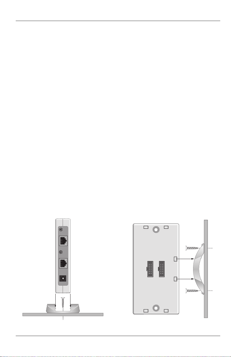
Shelf Mount/Wall Mount - With Base
If connected, remove the provided base from the Dock Adapter. Secure the base to the
shelf/wall with two screws. Snap the adapter back on to the base (Figures 11 & 12). If using
multiple Dock Adapters, printing a small adhesive label identifying The Source Dock address
and sticking it on The Source Dock Adapter is suggested to assist in making connections and
troubleshooting.
Note: The Dock Adapter can also be mounted under a shelf using the Base Clip Locks at the
top of the Dock Adapter.
Figure 11 Shelf Mount With Base Figure 12 Wall Mount With Base
17
Page 18
CONNECTIONS
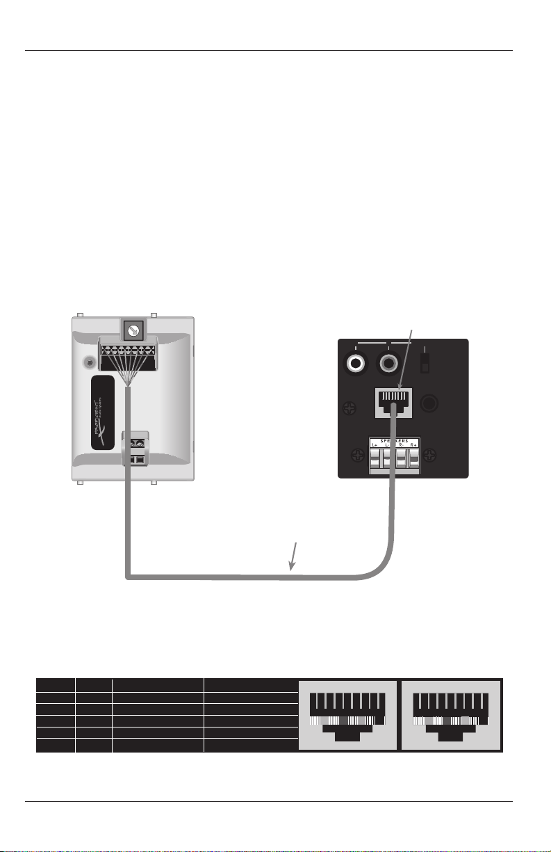
To M SERIES CONTROLLER
Zone Keypad Terminal
THE SOURCE
Punch-Down Block
NOTE: When making connections
to THE SOURCE punch-down block
ALWAYS pull the wire toward the
middle of THE SOURCE. Pulling
the wires toward the outside will
create diculty when installing the
keypad into the Mounting Bracket
and will probably cause wires to
become disconnected.
SPKRS
L
R
+
+ –
–
ZONE 4
L R
PRE-OUT
VC
NVC
KEYPAD
IR OUT
M6
Keypad
Connector
SEE CHART BELOW
for T568A & T568B
wiring termination.
Inter-Room
Twisted Pair
CAT5 Cable
1,000' (305m) Max.
IR
IR
+12
+12
GND
GND
485 A
485B
0
1
2
7
8
9
A
B
C
D
E
F
+ RELAY
- RELAY
IR
IR
+12
+12
GND
GND
485A
485B
Made in China
The Source Keypad
12 3 4 5 6 7 8
IR
IR
+12
+12
GND
GND
485 A
485B
0
1
2
3
4
5
6
7
8
9
A
B
C
D
E
F
+ R EL AY
- RE LAY
IR
IR
+12
+12
GND
GND
485A
485B
Made in China
The Source Keypad
Keypad RJ45 T568A Standard T568B Standard
12V Pin 2, 7 Green, White/Brown Orange, White/Brown
DATA/IR Pin 4, 5 Blue, White/Blue Blue, White/Blue
GND Pin 1, 8 White/Green, Brown White/Orange, Brown
485A Pin 3 White/Orange White/Green
485B Pin 6 Orange Green
1 2 3 4 5 6 7 8
T568B Standard
1 2 3 4 5 6 7 8
T568A Standard
THE SOURCE KEYPAD
110 Punch-Down Block
The Source Keypad features a 110 punch-down block wire connection point.
CAT5 is recommended for typical use. When making direct connections to the M4 or M6 be sure
to conrm color coding of each wire before making connections. (Refer to Figures 13 & 14)
Figure 13 Source Keypad to M4/M6 Connections
Figure 14 Source Keypad to M4/M6 Pinout
18
Page 19
CONNECTIONS
IR
IR
+12
+12
GND
GND
485 A
485B
0
1
2
3
4
5
6
7
8
9
A
B
C
D
E
F
+ RELAY
- RELAY
IR
IR
+12
+12
GND
GND
485A
485B
Made in China
The Source Keypad
Punch-Down Block Connections
1. Strip approximately 1" to 1½" from the outer jacket of the cable being connected to the
Source. DO NOT strip the individual conductors.
2. Using a proper 110 punch-down tool, connect each of the wires to the appropriate
terminals on the Source Keypad punch-down block (refer to Figures 13 & 14). When
making connections to the Source Keypad punch-down block ALWAYS pull the wire
toward the middle of the keypad . Pulling the wires toward the outside will create
diculty when installing the keypad into the Mounting Bracket and will probably cause
wires to become disconnected.
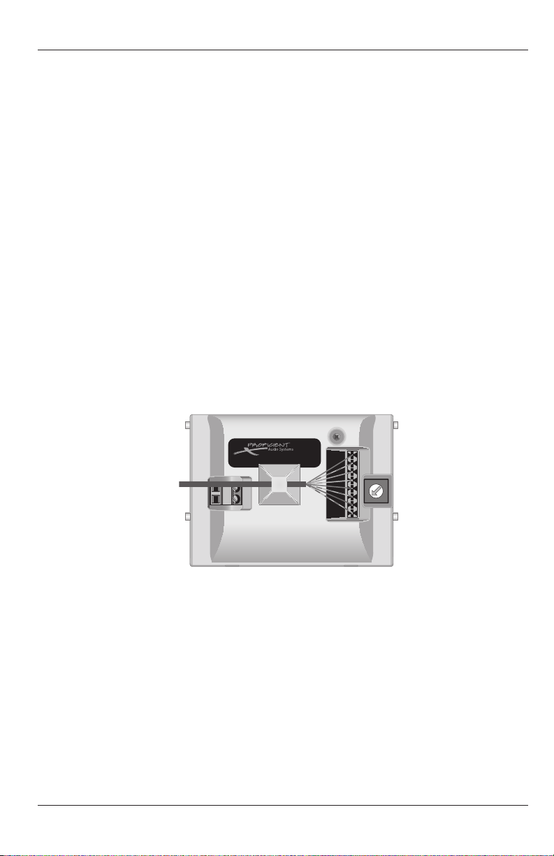
3. Prior to installing the keypad, attach the included Wire Retainer to the back of the Source
Keypad as shown in Figure 15. Remove the adhesive backing from the wire retainer and
attach with the wire tie oriented vertically as shown, with the retainer lock at the bottom.
Pull the retainer over the wire and down through the lock as shown. This will help
prevent the wires from becoming disconnected during installation.
4. Terminate and connect the head-end connection as appropriate.
Figure 15 Source Keypad Wire Retainer
19
Page 20
CONNECTIONS
Dock Adapter #1 Dock Adapter #2 Dock Adapter #3 Dock Adapter #4 Dock Adapter #5 Dock Adapter #6
12-Pin Ribbon Cable Interconnects
Top View
12-Pin Interconnect
Terminals (Side)
12V DC 1 AMP Adapter Port Aux. Input USB
Line Out
Expansion
Aux. Input
Source Dock
24V DC
The Source
Power Supply
Stereo Mini to RCA Cable
To M4 or M6
Source Input
CAT5 To M4 or M6
Expansion Port
CAT5
THE SOURCE DOCK ADAPTER THE SOURCE DOCK
THE SOURCE DOCK and DOCK ADAPTER (Single)
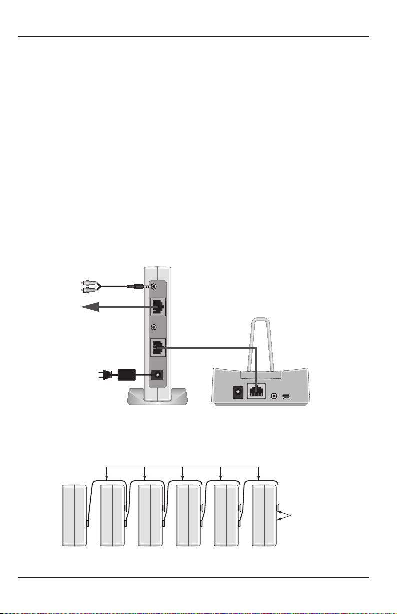
1. Mount the Source Dock Adapters as described in the “Installation” section.
2. Using a CAT5 patch cable with a pass-through conguration, connect the Expansion jack
on the Source Dock Adapter to an Expansion Port on an M4 or M6.
3. Using the included Stereo mini to RCA interconnect cable, connect the 3.5mm Line Out
Jack on the Source Dock Adapter to the appropriate Source Input on the M4 or M6.
4. Using a CAT5 patch cable with a pass-through conguration, connect the Source Dock
Port on the Source Dock Adapter to the Adapter Port on the Source Dock. If wire run is
greater than 250', an IR Power Supply 1.2A will be required. (Figure 16)
5. Aux Input - Using a Stereo mini to RCA interconnect cable, connect the L&R line level
audio output of a source to be added to the 3.5mm AUX Input Jack. This will allow
adding a local source to an M4/M6 Zone and being able to play the audio through the
M4/M6 amplier and Zone speakers. This input must be congured in Procient Editor
and is only selectable from the Source Keypads.
6. When all connections have been made and conrmed and the system is ready for
operation, connect a Procient 24V DC Power Supply (not included) to the 24V DC Jack on
the Source Dock Adapter. Plug the power supply into an unswitched 120V AC outlet.
Figure 16 Single Source Dock Adapter/Dock Connections
Figure 17a Multiple Source Dock Adapters, Top View
20
Page 21
CONNECTIONS
Line Out
Expansion
Aux. Input
Source Dock
24V DC
Line Out
Expansion
Aux. Input
Source Dock
24V DC
Line Out
Expansion
Aux. Input
Source Dock
24V DC
Line Out
Expansion
Aux. Input
Source Dock
24V DC
Line Out
Expansion
Aux. Input
Source Dock
24V DC
Line Out
Expansion
Aux. Input
Source Dock
24V DC
Dock Adapter #1 Dock Adapter #2 Dock Adapter #3 Dock Adapter #4 Dock Adapter #5 Dock Adapter #6
Source Dock #1 Source Dock #2 Source Dock #3 Source Dock #4 Source Dock #5 Source Dock #6
Stereo Mini
to RCA
To M4 or M6
Source In
Stereo Mini
to RCA
To M4 or M6
Source In
Stereo Mini
to RCA
To M4 or M6
Source In
Stereo Mini
to RCA
To M4 or M6
Source In
Stereo Mini
to RCA
To M4 or M6
Source In
Stereo Mini
to RCA
To M4 or M6
Source In
CAT5 To M4 or M6
Expansion Port
One Connection for
all Adapters
Pro c i e n t 2 4V D C
So u rc e P o we r S u p p l y
On e P o w e r s 6 A d a p t e r s
Line Out
Source Dock
Por t
Adapter
Por t
12-Pin Ribbon Cable
Interconnect
12-Pin Ribbon Cable
Interconnect
12-Pin Ribbon Cable
Interconnect
12-Pin Ribbon Cable
Interconnect
12-Pin Ribbon Cable
Interconnect
CAT5 C A T 5 CAT 5 CA T 5 CAT 5 CA T 5
THE SOURCE DOCK and DOCK ADAPTER (Multiple)
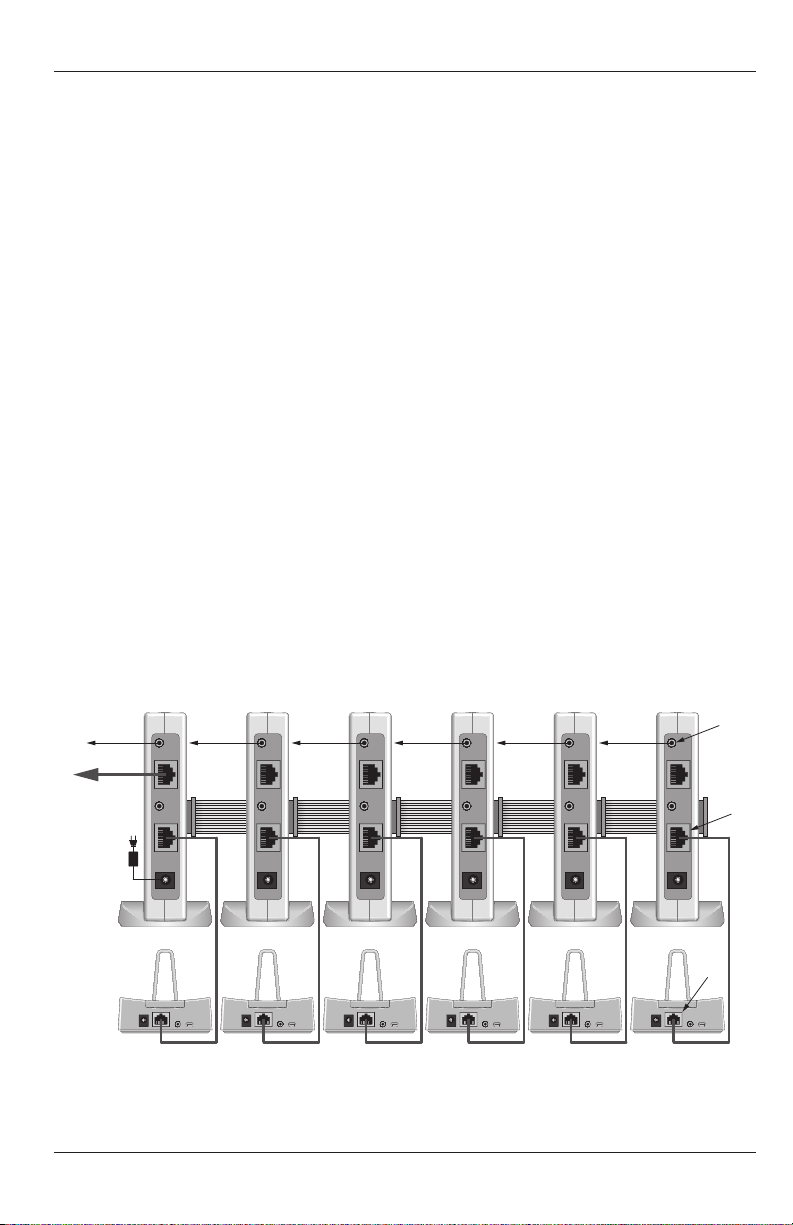
1. Mount the Source Dock Adapters as described in the “Installation” section.
2. Conrm connection of the 12-Pin Ribbon Cable Interconnects as shown in Figures 17a
and 17b.
3. Using a CAT5 patch cable with a pass-through conguration, connect the Expansion jack
on one of the Source Dock Adapters to the Expansion Port on an M4 or M6. (The 12-Pin
Interconnects create a bus for power, control and metadata to the additional units.)
4. Using the included Stereo Mini to RCA Interconnect Cables, connect the 3.5mm Line Out
Jack on each Dock Adapter to the appropriate Source Input on the M4 or M6.
5. Using a CAT5 patch cable with a pass-through conguration, connect the Source Dock
jack on each Source Dock Adapter to the Adapter Port on its specically matched Source
Dock. Repeat until all Adapters and Docks are connected. For each Source Dock wire run
that is greater than 250', a Procient Power Supply 1.2A will be required.
6. Aux Input - Using a Stereo Mini to RCA Interconnect Cable, connect the L&R line level
audio output of a source to be added as an additional to the Aux Input on the appropriate
Source Dock Adapter as congured in “Source Setup” in Procient Editor. This will allow
adding up to six additional sources to the M4/M6. These inputs must be congured in
Procient Editor and are only selectable from the Source Keypads.
7. When all connections have been made and conrmed and the system is ready for
operation, connect a Procient 24V DC Power Supply to the 24V DC Jack on one of the
Source Dock Adapters. This will provide power for up to six Source Dock Adapters. Plug
the Power Supply into an unswitched 120V AC outlet.
Figure 17b Multiple Source Dock Adapter/Dock Connections
21
Page 22

PROGRAMMING
PROGRAMMING WITH PROFICIENT EDITOR
The Procient Editor programming instructions provided with the Source are intended to provide direction for adding a Source Keypad, multiple Source Keypads, Source Dock(s) and Source
Dock Adapter(s), to Procient M4 and M6 Systems. If conguring a new system, start with the
“Programming With Procient Editor” section of the Procient Editor Advanced Programming
Guide for system conguration, source setup, power management, etc. Use this manual for
conguration and programming zones using Source Keypads.
Note: If only changing PMKs to Source Keypads, and not adding iPod/Source Dock/Source
Dock Adapter, follow the directions in Download Procient Editor and proceed to the “Adding
a Source Keypad to an Existing M4/M6 Project” section.
With the system installed at the job site or set up for test at the shop, the system is ready for
programming. Connect the 3.5mm Plug Transfer Cable between the Control Port on the M4
or M6 and the Com Port on a PC running Procient Editor (or the USB Port with the USB/Serial
Adapter). Power up the M4 or M6 and proceed as follows:
DOWNLOAD PROFICIENT EDITOR
Before programming with Procient Editor, always check www.procientaudio.com to verify
that the version of Procient Editor being used is the latest rev.
QUICK START GUIDE FOR SIMPLE SOURCE PROFICIENT EDITOR PROGRAMMING
Follow the instructions in this section if no source or zone changes other than replacing a PMK
with the Source are required.
1. Open an existing Project.
2. Under Project Content/Zone Setup, left click the zone the Source Keypad is going to be
added to.
3. In the Zone Setup Window, left click Name/Sources. If the Available Sources are
checked and not going to change, left click Apply. Check or uncheck any boxes to make
changes as needed.
4. In the Zone Setup Window, left click Keypad.
5. Under Graphic Keypad, left click to place a check mark in the box next to the Source. If
removing the PMK left click the PMK-1x box to uncheck the box and remove the PMK
from the zone. Left click Apply.
6. In the Zone Setup Window, left click Whole House /Mute.
7. If the Whole House/Party Mode and Mute Key Functionality settings are not going to
change, left click Apply, otherwise make desired changes and then left click Apply. See
the “Whole House/Mute” section for additional information.
8. Right click the Source icon in the zone being congured, then left click “The Source
Setup”. In the Zone # The Source Window, left click the appropriate Address Box to set
22
Page 23

PROGRAMMING
Keypad Address. If there is only one keypad per zone, all keypads can have the same
address (default address is “A”). If there is more than one keypad in a zone (PMKs and/
or Source keypads) the keypads in that zone must all have dierent Addresses. Left click
Apply. The Address will appear after the Source icon.
9. Under Project Content/Zone Setup, right click the zone icon for the zone being congured. In
the pop-up window, highlight and left click Place Default A/V Routing Commands.
10. Left click the Source icon for the keypad being congured. The Virtual Source, Button
Properties and Virtual Button List Windows will appear.
11. Left click the rst source on the Source List.
12. Left click the Volume Up Arrow on the Virtual Keypad. Left click the CMD M4 or M6
Cmds Tab, expand the Audio Level Commands Tab and double left click the Volume Up
Command for the Zone being programmed.
13. Right click the Volume Up Arrow and then highlight and left click Punch Key’s
Commands to make the Volume Up Command available to all sources. Left click Yes in
the pop-up. Repeat for Volume Down.
14. To program Mute, right click the inside section of the Volume Knob. In the pop-up, if
not checked, highlight and left click the Mute (Preamp) Key. This will program Zone and
Whole House Mute for all sources.
15. Right click the Power Button. In the pop-up, if not checked, highlight and left click Zone
Power O Key. This will program Zone and Whole House O for all sources.
16. To program Hard Keys by source, left click a source in the Source List. Left click the CMD
Library Tab, select a Brand and Device from the pull downs and double left click the
appropriate commands for the Hard Keys being programmed. Repeat for all sources.
17. To create and program Virtual Buttons, left click a source in the Source List. Right click
inside the Virtual Button List Window. Highlight and left click Add Multiple New Menu
Items. Type the names of the Virtual Buttons to be created in the Enter Item Name block
and add them to Item Names by left clicking the >> Button. When nished, left click OK.
The M6 tuners and The Source Docks provide metadata feedback to The Source Keypad
and control of these sources is not editable.
18. Left click the Virtual Button in the Virtual Button List. Left click the CMD Library Tab,
select a Brand and Device from the pull downs and double left click the appropriate
commands for the Virtual Buttons being programmed. Repeat for all sources.
19. Download the project to the M4 or M6 and test all functions. Make changes as needed
using the previous steps. For more in-depth description of the Source programming, see
the following sections.
23
Page 24
PROGRAMMING
ADDING THE SOURCE DOCK & SOURCE DOCK ADAPTER TO AN EXISTING PROJECT
With Procient Editor running, open the project that the Source is going to be added to.
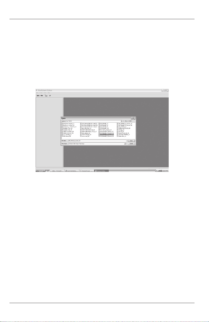
Open Project
1. In the Menu Bar, select File.
2. In the pull-down, highlight and left click Open.
3. In the Open Window, highlight and left click the project to be modied. The project will
open to the default screen as shown in Figure 18.
Figure 18 Opening an Existing Project
Source Setup
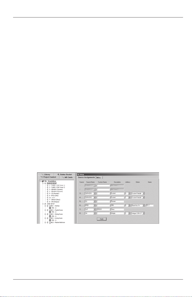
4. If adding iPod(s) using Source Dock(s) and Source Dock Adapter(s), with the Project
Content Tab selected, left click Source Setup. The M4/M6 Setup Window will appear.
(See Figure 19)
5. Left click the pull-down arrow for the source that is to change to iPod. (For the example
Source 6 will be used.) The M4/M6 Source List will open. Highlight and left click iPod.
Source 6 will change to iPod. The Source Assignments Tab will also change, now
featuring additional options for Source 6. (Refer to Figure 19)
6. In the Description block, type in a name for the iPod, such as NANO, 30G, etc.
7. In the Address block, if the iPod being added to Source 6 is the only iPod being added
using the Source Dock and Adapter, leave the Address set to ‘0’. If adding additional
iPods, Docks and Dock Adapters, set each to a dierent Address.
8. Under Option, if no additional source is going to be added, use the default setting: None.
If adding an additional source, left click the pull-down arrow and select: Dock Aux In or
Adapter Aux In. Dock Aux In allows stereo audio to be connected from a source at the
Dock location. That is, if the Dock is in a remote zone, a device such as a Video Game, XM
or SIRIUS Tuner, Cable Box, etc. can be added so the audio can be played through the
24
Page 25
PROGRAMMING
M4/M6 amplier and zone speakers. Adapter Aux In provides the same exibility for a
source connected to the Adapter. There can only be one Aux In connected per source,
but this allows the input capability of the M4 Controller to expand to 12 sources and the
M6 Controller to 14.
IMPORTANT NOTE: The sources connected to the Dock and Dock Adapter Aux Inputs
are only selectable via the Source Keypads. They are not available to PMKs and cannot be
selected by IR remote commands.
For the purpose of the example, the CD Changer that was connected to Source 6 on the
M4/M6 has now been replaced by an iPod, making the iPod available to all zones. The
CD Changer is actually dedicated to the Family Room, where coincidentally, the Source
is being installed. The CD Changer will be congured as the Source 6 Option Input in
Procient Editor (Figure 19) and connected to the Dock Aux In in the Family Room. All
zones will have access and control of the iPod (Source 6). Only zones with the Source
Keypads will have access and control of the cable box (Source 6a) which will appear in
the Source Main Menu as a regular source. Further, as an option, the CD Changer can be
unchecked in Zone Setup, for any zones other than the Family Room that get the Source
Keypads, to keep the CD Changer dedicated to the Family Room. In addition to dedicated
control, this will allow the CD Changer audio to feed through the M4/M6 amp and zone
speakers for the Family Room. See the “Connections” section for additional information.
9. In the Name block, type in the source name for the device being connected to the Aux
In. This name will appear in the Source List on the Source Display, so be sure to use a name
that will not confuse the user. If there is a CD player already available as a source through
the M4/M6, name the CD Changer connected to the Aux In: CD 2.
10. If no other changes are to be made, left click Apply in the M4/M6 Setup Window. This
will ‘save’ the new conguration. If additional Docks and Dock Adapters are being added,
repeat Steps 5-9 above for each new Dock/Adapter pair. Left click Apply to ‘save’ each.
Figure 19 Changing Source Setup
25
Page 26
PROGRAMMING
11. A warning window will appear advising: ‘The CD Changer has been changed to an iPod
Source...Do you still want to continue?’ Left click YES. If multiple source changes have
been implemented, a warning for each change will come up. Review each of these as it is
possible that an undesirable change has been made.
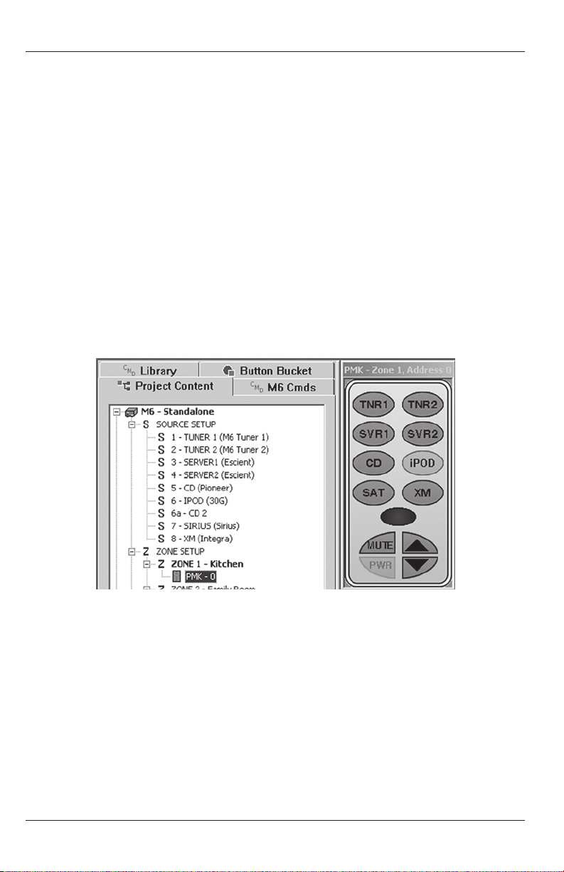
12. After the warning(s) have been cleared, the Source Setup under the Project Content Tab
will update to show the new source conguration. (Refer to Figure 20) Source 6 will have
changed to iPod and a new source, 6a will show CD2. Source 6a is the Option Source Input
(Dock or Adapter Aux In) congured in the previous steps. (Refer to Figure 19)
13. At this point the PMK Source Buttons will have also changed to indicate the new source
conguration. In the example, the CD 2 Button has now changed to iPod as shown in
Figure 20. All programming associated with Source 6 will need to be changed from
CD Changer commands to iPod commands for all keypads in all zones. Left click the
CMD Library Tab to open the IR Command Library. Left click the pull-down arrow next
to the Brands block and scroll the list until Procient appears. Highlight and left click
Procient. Expand the Source Folder by left clicking the ‘+’ sign or double left clicking
the folder icon. Next, expand the Source Dock Folder by left clicking the ‘+’ sign or
double left clicking the folder icon.
Figure 20 Updated Source Setup and PMK Conguration
Zone Setup
14. Under: Project Content/Zone Setup, select the PMK in Zone 1 by left clicking the green
PMK icon. The virtual PMK for Zone 1 will appear. Left click the iPod Source Button to
select the iPod ‘bank’ of commands. The iPod Source Button will highlight blue and all
commands programmed to that button will appear in the Button Properties Window.
15. Right click any commands in the Button Properties Command List that were
programmed for the CD Changer (or other now replaced source) then highlight and left
click Delete Command in the pop-up. The command will be deleted.
26
Page 27

PROGRAMMING
16. Double left click any desired command(s) in the CMD Library/Procient/Source/Source
Dock Command Library for PMK iPod control programming.
17. Repeat Steps 15-16 for all buttons within the iPod ‘bank’.
18. If all zones are identical in keypad conguration, (all use the same double or triple-gang
conguration), the new programming for the PMK in Zone 1 can be ‘cloned’ to the other
PMKs. Right click the Zone 1 PMK iPod Source Button. Highlight and left click Copy All
Source Bank Commands in the pop-up. Left click the PMK icon in any other zone with
an identical PMK setup to Zone 1. Right click the iPod Source Button. Highlight and left
click Paste Source Bank Commands to duplicate the PMK programming for iPod to the
selected zone. Repeat for all Zones with identical PMK conguration. Zones with dierent
PMK congurations will need to be programmed individually.
Download and Test
19. At this point it is suggested that the project be downloaded to the M4 or M6 to conrm
the changes to the PMKs and communication with the iPod/Dock/Dock Adapter. With
the PC running Procient Editor connected to the M4 or M6 with a Procient 3.5mm
Plug Transfer Cable or Transfer Cable with USB/Serial Adapter, either select ‘M4 or M6
CONTROLLER’ from the Menu Bar, then highlight and left click Download or left click the
Download Icon in the Tool Bar to transfer the updated project to the M4 or M6.
20. When Download is complete check PMKs for proper iPod control. Make programming
changes as needed by repeating previous steps.
21. At this point, existing system functionality for PMKs is updated and complete and the
Source programming begins.
ADDING A SOURCE KEYPAD TO AN EXISTING M4/M6 PROJECT
The Procient Editor programming instructions provided with the Source are intended to
provide direction for adding a Source Keypad, multiple Source Keypads, Source Dock(s) and
Source Dock Adapter(s), to existing M4 or M6 Systems. If conguring a new system, start
with the “Programming With Procient Editor” section of the Procient Editor Advanced
Programming Guide for system conguration, source setup, power management, etc. Use this
manual for conguration and programming zones using the Source keypads.
If adding iPod(s), Source Dock(s) and Source Adapter(s), be sure to have followed all
instructions in the previous sections for incorporating those components, updating Source
Setup and Zone Setup for proper system conguration and performance. If only adding
sources or upgrading PMKs to Source Keypads, be sure to have followed all instructions for
connections and installation in the previous sections. When adding a Source Keypad to an
existing project, Procient Editor does some of the work automatically in identifying sources
and placing them in the Source Main Menu. This helps assure that proper control commands
will be associated with the right source. To add a Source Keypad:
27
Page 28
PROGRAMMING
Open Project
1. If not already open, Open the M4 or M6 Project to be modied.
2. Under the Project Content Tab, conrm the source conguration for the system under
Source Setup. If the source conguration is correct, proceed to Step 3. If not, return
to the “Adding An iPod, Source Dock And Source Dock Adapter To An Existing Project”
section and follow all instructions.
Zone Setup
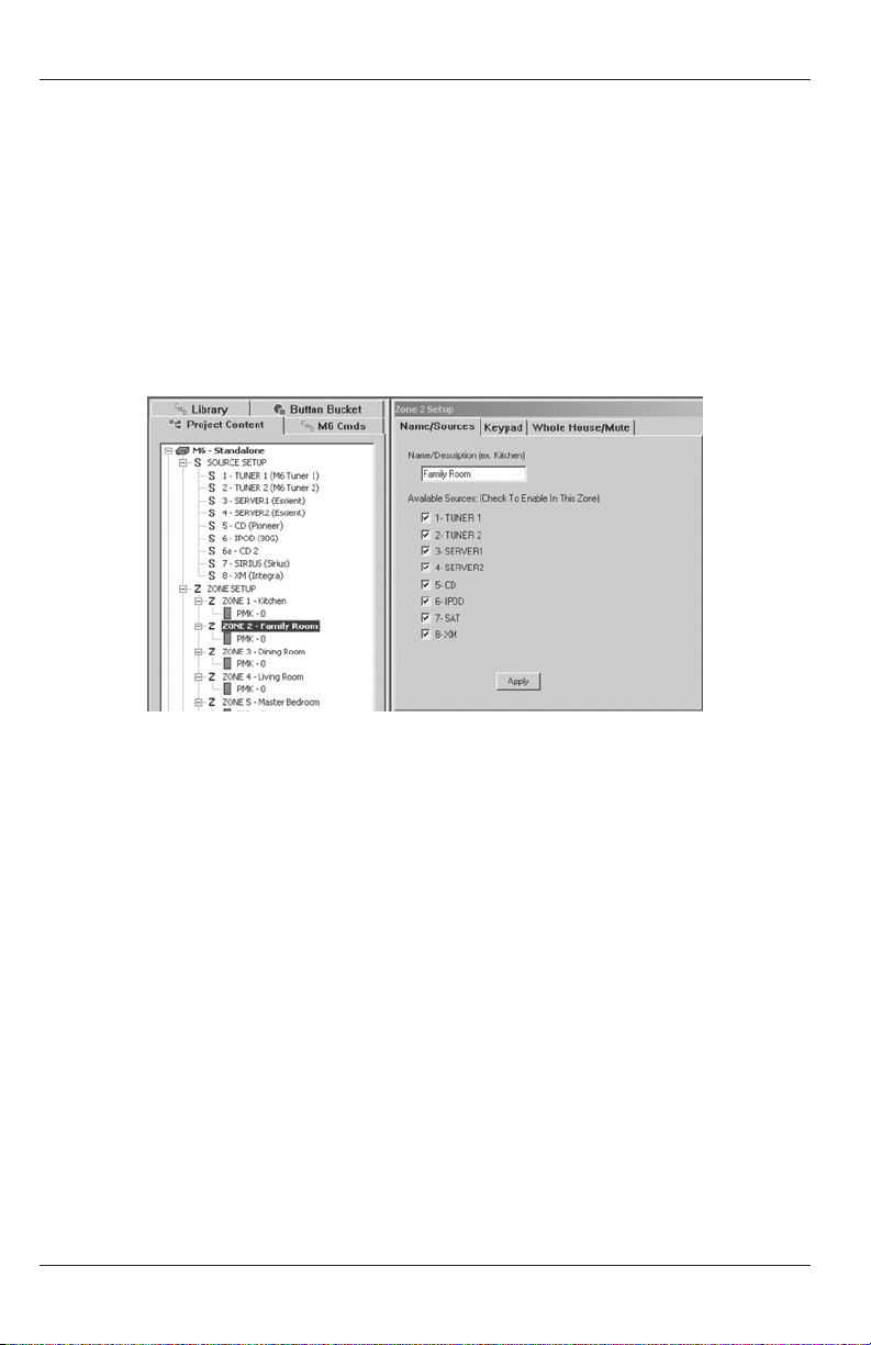
3. Under Project Content/Zone Setup, left click the Zone that the Source is going to be
added to - for this example, Zone 2. The Zone 2 Setup Window will appear as shown in
Figure 21.
Figure 21 Zone Setup Window
Name/Sources
4. If the Available Sources options are checked and not going to change, left click Apply.
(The CD Changer now connected as Source 6a or any other sources connected to the
Adapter or Dock Aux Inputs will not show in this list, but will automatically be available
to the Source Keypad and any other Source Keypads that get added to the system).
If the Available Sources options are to be changed, check or uncheck the sources as
appropriate. Left click Apply.
Keypad
5. To add a Source Keypad to the zone, left click the Keypad Tab. (PMKIR, PFK, PNK) should
be checked. Under Graphic Keypad, left click in the Source Box to place a check mark in
the box. This will place a Source Keypad in the Zone Setup. If the PMK is being replaced
with the Source Keypad, left click the PMK box to uncheck the PMK. This will remove the
PMK from the Zone Setup. If the PMK is to remain installed, leave the PMK box checked.
Left click Apply. For the example system, the PMK has been removed and replaced with
a Source Keypad. As soon as Apply is clicked, under Project Content, the PMK is removed
from the Zone Setup and the Source Keypad Icon appears. (See Figure 22)
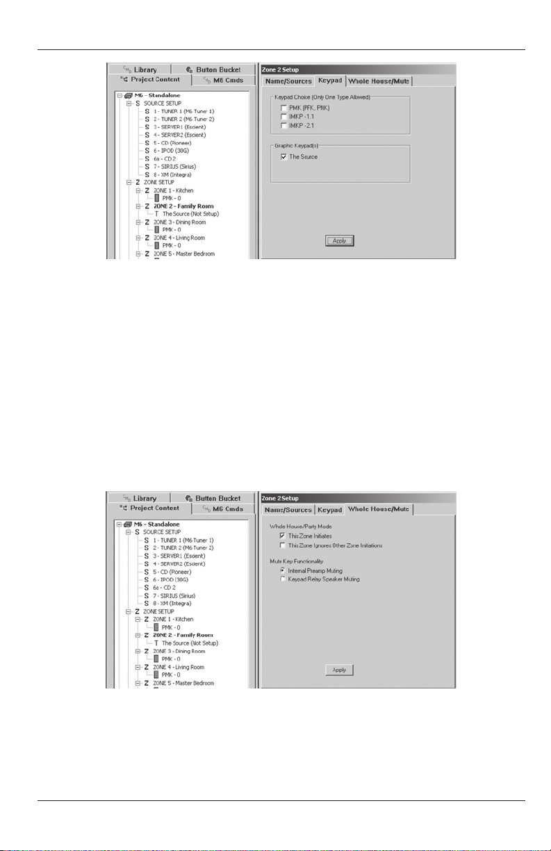
28
Page 29
PROGRAMMING
Figure 22 Zone Setup Keypad Tab
Whole House/Mute
6. Left click the Whole House/Mute Tab to conrm Whole House and Mute Key
Functionality. These functions should have already been congured in the existing
project. Under Whole House/Party Mode, “This Zone Initiates” should be checked to
enable Party Mode from a press and hold of the Click Button when selecting a source
on the Source Keypad. “This Zone Ignores...” should be checked to lock out Party Mode
commands from other zones. Under Mute Key Functionality, “Internal Preamp Muting”
should be checked to use the M4 or M6 zone preamp muting function. “PMK Relay
Speaker Muting” should be checked when using a Speaker Mute Relay for muting
individual rooms in sub-zone expansion applications (multiple rooms in a single zone).
When Zone Whole House/Mute functions are set, left click Apply. (Refer to Figure 23)
Figure 23 Zone Setup Whole House/Mute Tab
Keypad Address
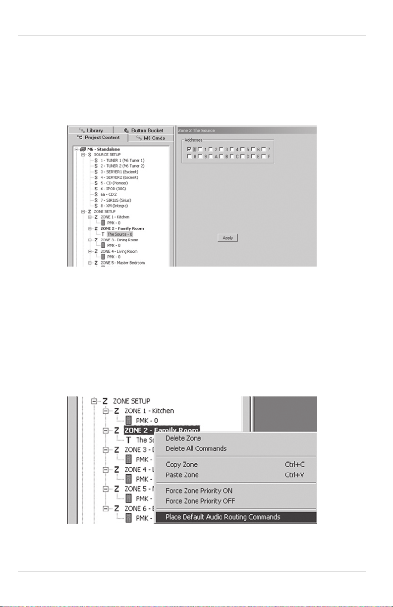
7. Any keypad whether an PMK or Source must have its Address congured in Procient
Editor. If there is only one keypad per zone, all keypads can be set to the same Address.
29
Page 30
PROGRAMMING
Any time there is more than one keypad in a zone, each of the keypads within that zone
must be set to a dierent Address. Right click the PMK or Source Icon in a particular
zone. Left click the PMK or Source Setup pop-up. Left click the desired box to set keypad
Address. For the example, ‘0’. Left click Apply. The Keypad Address will appear next to
the Keypad Icon in Zone Setup. A maximum of three Source Keypads in a zone. (Refer to
Figure 24)
Figure 24 Zone Setup Keypad Address
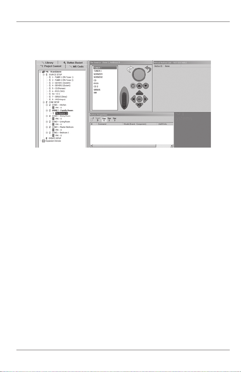
Default Audio Routing Commands
8. To assure that the sources connected to the M4 or M6 will be properly routed to the local zone,
a set of default Audio routing commands can be assigned to the source icons on the Source
Keypad. Under Project Content/Zone Setup, right click the Zone 2 icon. Highlight and left click
Place Default A/V Routing Commands. The M4/M6 Internal Commands for all source Audio
signal routing will be automatically assigned to all sources available to the Source Keypad in
Zone 2. (Refer to Figure 25)
Figure 25 Place Default A/V Commands
30
Page 31
PROGRAMMING
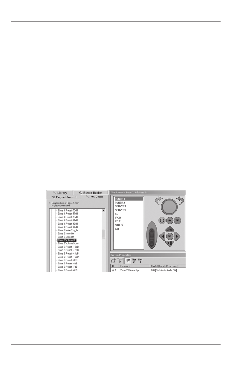
This completes Zone Setup for integrating the Source Keypad into Zone 2. Left click the
Source Icon under Project Content/Zone Setup/Zone 2. The virtual Source Keypad will
appear along with the Button Properties Window and the Virtual Button Window. (Refer to
Figure 26)
Figure 26 Virtual Source Keypad
PROGRAMMING THE VIRTUAL SOURCE KEYPAD
Virtual Source Keypad Window
When an unprogrammed the Source Keypad appears on screen, Procient Editor has already
loaded the M4/M6 Source Icons, to assist in keypad programming. By doing so, Procient
Editor reduces the possibility of accidental omission of sources or associating sources with
the wrong input. The Virtual Source Keypad Window displays the Zone Number and Keypad
Address for reference. The Source Icons in the Source List have the same programming and
performance capabilities as source keys on PMKs. The dierence being, PMK source keys are
hard buttons that are pressed, The Source Keypad source keys are Virtual Buttons on The
Source Keypad LCD that are selected with the Scroll Wheel and Click Button. The Source
Icons are programmed the same as any other key, by selecting the icon and double clicking
commands under the CMD M4/M6 Cmds Tab or CMD Library Tab. Programmed commands
appear in the Button Properties Window, consistent with Procient Editor programming.
Note: The Scroll Wheel, Click Button and Menu Key are not programmable. They have un-
removable factory programmed functions for scrolling lists and menus on the LCD (via the
Scroll Wheel), selecting items from those lists and menus (via the Click Button) and returning
to either The Source Main Menu or selecting iPod Menus depending upon the current Source
function (via the Menu Button). When a source other than iPod is selected, a press of the
Menu Key returns the display to the Source Main Menu. When iPod is selected, and the iPod
is playing, a press of the Menu Key returns the display to the previous iPod Menu level. In any
iPod mode, a press & hold of the Menu Button will return the display to the Source Keypad
Main Menu.
Virtual Button List Window
When any source is selected on the Source Keypad, the information in the LCD will change
to the Virtual Buttons associated with that source. Any menu or list of commands associated
with controlling a particular device, or the system, can be congured for display.
31
Page 32
PROGRAMMING
The Virtual Button List Window is where these menus and lists of commands are created.
Virtually any command for any device that will be connected to an M4/M6 System can be
programmed to a Source Virtual Button. A pop-up tool allows creation of the Virtual Buttons
by simply typing in the name of the function, i.e. Play, Stop, Menu, Aspect Ratio, etc. Once the
Virtual Button has been created, any command from the Procient Editor Command Library
whether an M4/M6 Internal Command, IR command or RS232 command can be associated
with these Virtual Buttons. If the required IR or RS232 commands are not already in the
Library, they can be added by either learning the IR commands with the Procient Command
Interface Module or by using the RS232 Command Properties Tool for creating and editing
RS232 commands. Refer to the Procient Editor Advanced Programming Guide sections
“Learning IR Commands” and “RS232 Commands” for additional information.
As when programming any other key in Procient Editor, the commands associated with the
Virtual Buttons are displayed in the Button Properties Window. Virtual Buttons have the same
properties as PMK keys in that they can execute single commands, or macros and for truly
advanced applications access tiered commands as well.
To program the Source Keypad shown in Figure 26:
1. Left click the Tuner 1 Source Icon on the Virtual Keypad. It will highlight blue. This
indicates the Tuner 1 ‘bank’ has been selected.
Volume
2. Left Click the Volume Knob Up Arrow. The Tuner 1 icon will turn red indicating which
source is being programmed and the Up Arrow will highlight blue to indicate which
button is being programmed. (Figure 27)
Figure 27 Placing The Volume Up Command
3. Left click the CMD M4/M6 Cmds Tab and expand the Audio Level Commands Tab by left
clicking the ‘+’ sign or double left clicking Audio Level Commands. The list of all M4/M6
audio commands will open.
4. Scroll down the list to nd the Zone 2 Commands. Double left click Zone 2 Volume Up.
The Zone 2 Volume Up Command will appear in the Button Properties Window.
32
Page 33
PROGRAMMING
Right click the Volume Up Arrow. In the pop-up, highlight and left click Punch Key’s
Commands to make the volume up command available to all sources.
5. Next, left click the Volume Knob Down Arrow. Double left click Zone 2 Volume Down
in the CMD M4/M6 Cmds List. The Zone 2 Volume Down Command will appear in
the Button Properties Window. Right click the Volume Down Arrow. In the pop-up,
highlight and left click Punch Key’s Commands to make the volume down command
available to all sources.
Mute
6. Next is the Mute Button. The Volume Knob can be pushed in to execute a programmed
command or macro. It is recommended that the Knob press function be used for Zone
Mute. For this example, M4/M6 pre-amp zone mute will be used.
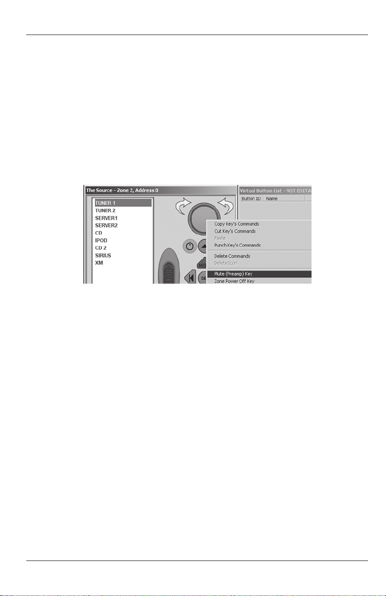
Figure 28 Placing The Zone/Whole/House Mute Command
Right click the inside section of the Volume Knob. In the popup, if not already checked,
highlight and left click the Mute (Preamp) Key as shown in Figure 28. This will congure
the key for Zone and Whole House Mute and punch the commands to all banks. The key
will highlight green to indicate special whole-house functionality.
When this button is pressed for less than 2 seconds, the zone will mute. When it is
pressed again for less than 2 seconds, it will un-mute. When the Mute Key is pressed for
longer than 2 seconds, this initiates whole-house muting (all zones mute). When pressed
again for longer than 2 seconds, all zones are un-muted.
Power
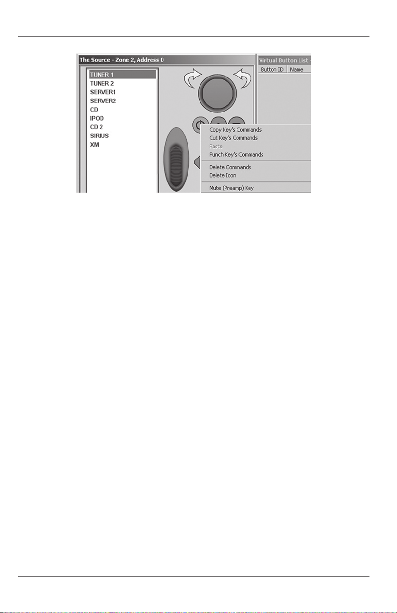
7. Right click the Source Keypad Power Button. In the pop-up, if not already checked,
highlight and left click Zone Power O Key as shown in Figure 29. This will congure the
key for Zone and Whole House O and punch the commands to all banks. The key will
highlight green to indicate special whole-house functionality.
When the Power Key is pressed for less than 2 seconds, the local zone will turn o, and
typically, the common sources will stay on until the last zone is turned o. Additionally,
when the Power Key is pressed for longer than 2 seconds, this initiates whole house
power o (all zones will turn o) and this action will typically also turn o the common
sources.
33
Page 34
PROGRAMMING
Figure 29 Placing the Zone/Whole-House Power Command
PROGRAMMING CONTROL OF SOURCES
The Source Keypad can be programmed to control any of the sources connected to an M4/M6
System by using either the Hard Keys or Virtual Buttons. Programming is consistent with standard
Procient Editor procedures. Hard Key programming should be for the most commonly used
commands, Play, Skip, Channel Up/Down, etc. Virtual Buttons can be programmed for control of
any source function for which an IR or RS232 command is available in the Command Library. For
example, if programming control of a CD Changer, commands for anything from random play to
direct disc selection can be setup as a Virtual Button.
Since the process is essentially the same for all sources, a general example using a CD Changer
will be used. Use the following instructions for other sources, by programming appropriate
commands by source.
Note: When used with a M6, the Source Keypad shows its powerful simplicity. The Preset channel frequencies and control commands for the M6 Internal Tuners are automatically displayed
on the Source LCD. This is a default function of the M6 and the Source Keypad. No programming
is necessary for control of the M6 Internal Tuners when controlled with the Source Keypad.
PROGRAMMING HARD KEYS
1. If not already open, left click the CMD Library Tab. From the Brands Pull-Down either
left click the pull-down arrow and scroll the list for the CD Changer Brand being used
or left click the Brands Box and type in the name of the CD Changer Brand. Expand the
CD Tab by left clicking the ‘+’ sign or double left clicking the CD Icon. In some cases, a
subdirectory of CD commands will appear. Some manufacturers have multiple code
groups for certain devices. A bit of trial and error may be necessary to determine which
code group is correct. Typically, testing commands such as power, play and stop will
indicate the proper code group. Sometimes a visual inspection of the list can be helpful
to see if certain special commands are available in one list or another. If any commands
are not available, they can be learned into Procient Editor. If it is necessary to learn
commands, refer to the “Learning IR Commands” section of the Procient Editor
Advanced Programming Guide.
2. Left click the CD Source Icon on the Virtual Keypad to select CD. It will highlight.
34
Page 35

PROGRAMMING
3. Left click the Arrow Up Button. Under CMD Library, double left click the Next Disc
Command. (Program for next disc if using a CD Changer otherwise select another
function such as Fast Forward or other appropriate command.)
4. Left Click the Arrow Down Button. Under CMD Library, double left click Previous Disc.
(Program for previous disc if using a CD Changer otherwise select another function such
as Reverse Play or other appropriate command.)
5. Left click the Previous Track Button. Under CMD Library, double left click Chapter/Skip
Down.
6. Left click the Next Track Button. Under CMD Library, double left click Chapter/Skip Up.
7. Left click the Play/Pause Button. Under CMD Library, double left click Play or Play/Pause
depending upon code availability.
This programming will provide basic transport control using the Hard Keys. To program
additional commands, Virtual Buttons can be added as needed.
PROGRAMMING VIRTUAL BUTTONS
Note: The default functionality of the Source Keypad when used with iPod, replicates the
genius of the iPod Menu system on the Source LCD. Therefore, no Virtual Buttons can be
congured for use with iPod. Likewise, some other devices, (Servers, XM Tuners) can be
congured for 'direct control' using a Procient Control Module, that allows RS232 control of
appropriately featured products. Some of these types of devices have been pre-congured in
Procient Editor (Source Setup/Option). Virtual Buttons cannot be programmed for any device
selected in Source Setup/Option.
8. With CD selected on the Virtual Keypad, right click inside the Virtual Button List Window.
9. If only adding one Virtual Button, highlight and left click Add New Menu Item. In the
New Item Window, type in the function and left click OK. Skip to Step 11.
10. If adding multiple Virtual Buttons, right click inside the Virtual Button List Window,
highlight and left click Add Multiple New Menu Items. In the New Source Menu Items
Window, type in the rst function name in the Enter Item Name Block. Either left click
the >> Button or press the return key on the PC keyboard to add the function to the
Item Names List. (Refer to Figure 30) To remove items from the ‘Add New’ list, highlight
the entry and left click the << Button. When all functions have been added to the Item
Names List, left click OK. To remove items from the Virtual Button List, right click the
item, then highlight and left click Delete Item.
11. To associate IR or RS232 commands to the Virtual Buttons, if not already open, left click
the CMD Library Tab. Select the Brand and Device being programmed as described in
Step 1 above.
12. Left click the Virtual Button to be programmed. Double left click the IR or RS232
command in the CMD Library. A red asterisk will appear next to the function in the
Virtual Button List to indicate an associated command or macro. The command will
appear in the Button Properties Window. (Refer to Figure 31) Repeat for all Virtual
Buttons.
35
Page 36
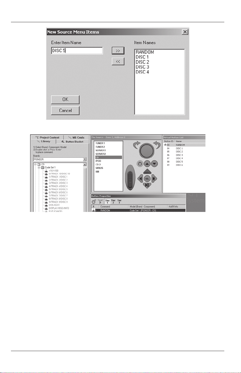
PROGRAMMING
Figure 30 Creating DVD/CD Virtual Buttons
Figure 31 Placing IR Commands On Virtual Buttons
Macros
13. Virtual Buttons can be programmed to execute macros using standard Procient Editor
programming method. Left click the Virtual Button to be congured as a macro. Double
left click a command from the CMD Library. It will appear in the Button Properties
Window. Navigate the CMD Library to nd the next command to be added to the macro.
Double left click the command. Repeat until all commands for the macro have been
programmed.
Delays
14. Delays can be added between commands in a macro by left clicking the Clock Icon in
the Button Properties Window. If adding a delay to an existing macro, it will appear at
the bottom of the Command List in the Button Properties Window. Left click and drag
the delay to the desired location between commands. A red line will appear between
commands to act as a guide as to where the delay will be placed. To adjust the duration
of the delay, double left click the delay in the Command List. The Delay Properties
Window will appear. Either type in the duration from 0.1 to 20.0 seconds or use the arrow
up/down buttons to set. Left click OK to enter.
36
Page 37

PROGRAMMING
SERVER 1
SERVER 2
CD
IPOD
TUNER 1
TUNER 2
SOURCE NOT SELECTED
OFF
15. Repeat the previous steps to program the Source Keypad for all other sources using
the appropriate Brand/Device Commands for each source from the CMD Library. For
commands not found in the Library, refer to the “Learning IR Commands” and “RS232
Commands” sections of the Procient Editor Advanced Programming Guide.
OPERATING THE SOURCE KEYPAD
The following describes basic source, zone, and system control in a typical installation.
Functions may vary given the programming options for the Hard Keys and Virtual Buttons.
POWER ON
1. Roll the Scroll Wheel to highlight a source on the LCD. (If the Keypad is in ‘Standby’,
rolling the Scroll Wheel or pressing any button will wake up the Keypad.)
2. Press the Click Button to select the source. The Zone will turn ON. The source selected
will be displayed at the top of the LCD. (Refer to Figure 33)
POWER OFF
Zone
1. Press the Zone Power O Key for less than 2
seconds. A red OFF and the message: “Source
Not Selected” will appear at the top of the LCD.
(Refer to Figure 32) Unless the local zone is the
last zone to be turned o, the zone will turn
o and the common sources will stay on. If the
local zone is the last zone to be turned o the
common sources will turn o as well.
Whole House
1. Press and Hold the Power O Key for longer
than 2 seconds. All zones and sources will turn
o, unless “This Zone Ignores Other Zone
Initiations” is selected under Zone Setup/Whole
House/Mute in Procient Editor for a given zone.
If selected, that zone will ignore the Whole
House Power O Command and the common
sources will stay on until the last zone is turned o.
SELECT A SOURCE
1. Roll the Scroll Wheel to highlight a source on the LCD. (If the Keypad is in ‘Standby’
rolling the Scroll Wheel or pressing any button will wake up the Keypad.)
2. Press the Click Button to select the source. The Zone will turn ON. The source selected
will be displayed at the top of the LCD. (Refer to Figure 33)
Figure 32
Source Keypad Main Menu
37
Page 38

OPERATING THE SOURCE
DISC 2
DISC 3
DISC 4
DISC 5
RANDOM
DISC 1
CD
ADJUST VOLUME
1. Rotate the Volume Knob clockwise to turn volume up. (The blue LEDs surrounding the
knob will provide a visual reference to the volume setting.)
2. Rotate the Volume Knob counter-clockwise to turn volume down. (The blue LEDs
surrounding the knob will provide a visual reference to the volume setting.)
MUTE
Local Room or Zone Mute
Pressing the Volume Knob for less than 2 seconds will mute/un-mute a local room or zone.
1. Push the Volume Knob to mute the zone preamp or local speakers controlled with
Speaker Relay Mutes. A red MUTE will appear at the top of the LCD.
2. Push the Volume Knob to un-mute the zone preamp or local speakers. The red MUTE at
the top of the LCD will turn o.
Whole House Mute
Pressing the Volume Knob for longer than 2 seconds will mute/un-mute the entire system,
(all zones, speaker relay mutes) unless “This Zone Ignores Other Zone Initiations” is selected
under Zone Setup/Whole House/Mute in Procient Editor for a given zone. If selected, that
zone will ignore the Whole House Mute Commands.
1. Press and Hold the Volume Knob for longer than 2 seconds to mute all zone preamps
and speakers controlled with Speaker Relay Mutes. A red MUTE will appear at the top of
the LCDs of all Source Keypads in the system and the selected Source Button will blink
about once per second in zones controlled with PMK's.
2. Press and Hold the Volume Knob for longer than 2 seconds to un-mute all zone
preamps and speakers controlled with Speaker Relay Mutes. The red MUTE will turn o
at the top of the LCDs of all the Source Keypads in the system and the selected Source
Button will resume constant illumination in zones controlled with PMK's.
SOURCE KEYPAD CONTROL
CD, Servers, SIRIUS, XM, etc.
1. From the Source Keypad Main Menu, roll the
Scroll Wheel to highlight a source and then press
the Click Button to select the source. The selected
source name will appear at the top of the LCD. Any
Virtual Buttons programmed for that source will
appear in the LCD. (Refer to Figure 33)
2. Press the Hard Keys for basic device controls as
programmed such as Play, Pause, Skip, etc.
3. Roll the Scroll Wheel to highlight Virtual Button
functions as programmed.
4. Press the Click Button to execute the Virtual
Button function highlighted in Step 3.
38
Figure 33 CD Virtual Buttons
Page 39
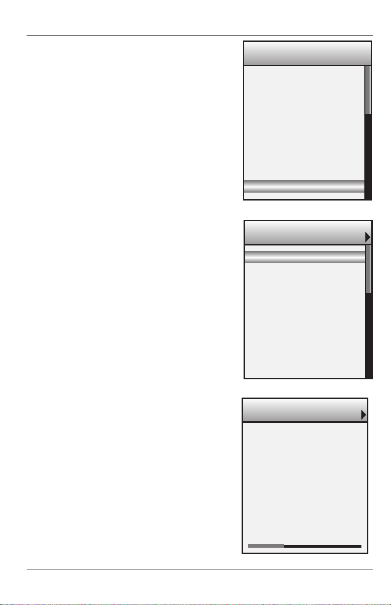
OPERATING THE SOURCE
P3 93.1 MHz
P4 93.9 MHz
P5 95.5 MHz
P6 106.7 MHz
P1 91.5 MHz
P2 92.3 MHz
TUNER 1 106.7 MHz
Albums
Genres
Songs
Composers
Playlist
Artists
NANO
Chevelle
Wonder What’s Next
1:07 5:44
5 of 11 R
The Red
NOW PLAYING
M6 Tuners
All M6 Tuner Preset Frequencies and Controls will default
to the Virtual Buttons. Additional controls may have
been programmed to the Hard Keys.
1. Roll the Scroll Wheel to highlight Tuner 1 or 2.
2. Press the Click Button to select the highlighted
Tuner. The selected tuner will appear at the top of the
LCD with the Presets and functions displayed in the
LCD. (Refer to Figure 34)
3. Roll the Scroll Wheel to highlight a desired Preset.
4. Press the Click Button to select the Preset
highlighted in Step 2.
5. Use the Scroll Wheel and Click Button to highlight
and execute Tuner functions such as AM/FM, Tune
Up/Down, etc.
iPod
All iPod functions (typical iPod Menus) will default to
the Virtual Buttons. Additional controls may have been
programmed to the Hard Keys.
1. Roll the Scroll Wheel to highlight an iPod.
2. Press the Click Button to select the highlighted
iPod. The selected iPod will appear at the top of the
LCD and the iPod Main Menu will open in the LCD.
(Refer to Figure 35)
3. Roll the Scroll Wheel to highlight an iPod Menu
Option: Playlists, Artists, Albums, etc.
4. Press the Click Button to select the Menu Option
highlighted in Step 2. The selected menu will
appear at the top of the LCD.
5. Repeat steps 3-4 until the Now Playing Screen
appears. (Refer to Figure 36)
6. Press the Hard Keys for basic iPod functions
such as Play/Pause and Track Skip Fwd/Rev if
programmed.
7. Press the Menu Button to return to the previous
iPod Menu level.
8. Press and Hold the Menu Button for longer than 1
second to return to the Source Keypad Main Menu.
39
Figure 34 M6 Tuner Virtual Buttons
Figure 35 iPod Main Menu
Figure 36 iPod Now Playing Screen
Page 40

OPERATING THE SOURCE
PARTY MODE
Party Mode allows playing a selected source in all zones from a simple Press and Hold of the
Click Button.
1. Roll the Scroll Wheel to highlight the desired Source. (If the Keypad is in ‘Standby’ rolling
the Scroll Wheel or pressing any button will wake up the Keypad.)
2. Press and Hold the Click Button for longer than 2 seconds. All zones will turn ON to the
selected source, unless “This Zone Ignores Other Zone Initiations” is selected under
Zone Setup/Whole House/Mute in Procient Editor for a given zone. If selected, that
zone will ignore the Party Mode Command and will continue in its current state (OFF or
playing a dierent source). The LCD on all Party Mode Keypads will display the selected
Source and a red Party will appear in the header. If an iPod is selected the LCD will also
display the iPod Main Menu. If an external source is selected, the Virtual Buttons are
displayed.
ZONE SETTINGS (Treble and Bass)
From the Source Keypad Main Menu:
1. Roll the Scroll Wheel and highlight Zone Settings.
2. Press the Click Button. The Zone Settings Menu will appear.
3. Roll the Scroll Wheel to highlight Treble or Bass.
4. Press the Click Button. The selected parameter will appear at the top of the LCD.
5. Roll the Scroll Wheel to adjust Treble or Bass Up/Down.
6. When the desired change has been made, press the Click Button to ‘Save’ the setting.
7. Press the Menu Button to return to the Source Keypad Main Menu.
KEYPAD SETTINGS
In the Source Keypad Main Menu is an option called Keypad Settings. These settings are user
denable preferences for keypad performance and appearance including: Button Intensity,
LCD Intensity, Button Standby, LCD Standby, Beeper and Theme. These settings are adjustable
only at the keypad and can be changed at any time. Adjustments are made using the Scroll
Wheel and Click Buttons.
Button Intensity
This setting adjusts the Hard Key and Scroll Wheel back-light level in increments of 1%
from 0-100%.
LCD Intensity
This setting adjusts the LCD back-light level in increments of 25% from 25-100%.
Standby Timeout
This setting adjusts the duration of the Hard Key and LCD Backlighting in varying increments
from 1 second to always on.
40
Page 41

OPERATING THE SOURCE
Button Standby
This setting adjusts the intensity of the Hard Key standby backlight in increments of 1%
from 0-100%.
LCD Standby
This setting adjusts the intensity of the LCD standby backlight in increments of 25% from
OFF-100%.
Beeper
This setting turns an audible click that conrms button presses click On and O.
Theme
This setting selects dierent color schemes for the information displayed on the LCD.
To adjust keypad settings:
1. In the Source Keypad Main Menu, highlight and select Keypad Settings using the
Scroll Wheel and Click Button.
2. Using the Scroll Wheel, highlight the setting to be adjusted.
3. Press the Click Button to select. The selected Setting will appear at the top of the LCD.
4. Using the Scroll Wheel, adjust the selected setting to the desired value.
5. Press the Click Button to set.
6. Repeat Steps 2-5 for all settings and values.
7. When nished, press the Menu Button. The message: Zone Setup will appear. Done
will ash for a second and the keypad will return to the last selected source.
KEYPAD RESET
Though highly unlikely, the Source Keypad can lock up under certain circumstances. The
Keypad Reset procedure will unlock the keypad without aecting any of the Procient Editor
programming or local Zone or Keypad Settings. To unlock the keypad:
1. Press and Hold the Volume Knob for 5 seconds. The keypad should return to normal
operation.
41
Page 42

SPECIFICATIONS
The Source Keypad
Dimensions 3⁄" W x 2⁄" H x 1 ⁄" D
LCD High Resolution 16 bit Color LCD
Hard Keys 7 back-lit, congurable,
programmable, 1 xed Menu Key
System Connector 110 Style Four Pair Punch-Down
Terminal
Address Switch 16 Position Rotary Switch
Speaker Mute Relay +12V DC @ 17mA
Power Requirement 12V DC
The Source Dock Adapter (Without Base)
Dimensions 1" W x 4⁄" H x 2" D
Audio Out Stereo 3.5mm Mini Jack
M4/M6 Expansion Connection RJ45 Jack
Aux Audio In Stereo 3.5mm Mini Jack
Source Dock Connection RJ45 Jack
Source Adapter Bus 12-Pin Interconnect System
Power Requirement 24V DC
The Source Dock (Including iPod Bracket)
Dimensions 3¼" W x 3⁄" H x 3¼" D
Source Dock Adapter Connection RJ45 Jack
Aux Audio In Stereo 3.5mm Mini jack
USB USB Mini B
iPod Connection Standard iPod Dock Connector
Power Requirement 12V DC
Features and specications are subject to change without notice.
42
Page 43

LIMITED 2YEAR WARRANTY
Should you have any questions regarding this, or any other Procient Audio Systems product,
please call our service hotline at 877.888.9004.
We are available to assist you every weekday, except holidays, between the hours of 7:00 a.m.
and 5:00 p.m. PST.
LIMITED TWO-YEAR WARRANTY
Procient Audio Systems (“Procient”) warrants to the original retail purchaser only (“you”) that this product will be free
from defects in materials and workmanship for a period of two years (the “Warranty Period”), subject to the limitations
and exclusions set out in this Limited Warranty. This warranty is not transferable to subsequent owners of the product.
If you discover a defect in material or workmanship within the Warranty Period, you can obtain warranty service by
contacting Procient during the Warranty Period at 877.888.9004 or techsupport@procientaudio.com or by sending
the product to Procient at 940 Columbia Avenue, Riverside, CA 92507 or to the dealer from whom you purchased the
product. Defective products must be shipped, prepaid and insured, together with proof of purchase. Warranty service
requests made without proof of date of purchase will be denied. Freight collect shipments will be refused. It is preferable
to ship this product in the original shipping container to lessen the chance of transit damage. In any case, the risk of loss
or damage in transit is to be borne by the purchaser.
If, upon examination by Procient, it is determined that the unit is in fact defective, Procient will, at Its option:
• Repair or replace the product at no additional charge; or
• If the model is no longer available and cannot be repaired eectively, replace the unit with a current model of equal or
greater value. In some cases where a new model is substituted, a modication to the mounting surface may be required.
If mounting surface modication is required, Procient assumes no responsibility or liability for such modication.
Procient will bear the cost of returning the repaired or replaced product to you, freight prepaid. All replaced parts and
product become the property of Procient Audio Systems. The foregoing is your sole and exclusive remedy for breach
of warranty. If the product is not found to be defective, Procient will contact you to arrange for return of the product
to you, at your expense.
EXCLUSIONS:
• This Warranty does not include service or parts to repair damage caused by accident, disaster, misuse, abuse, negligence,
inadequate packing or shipping procedures, commercial use, voltage inputs in excess of the rated maximum of the unit,
or service, repair or modication of the product by unauthorized dealers. This Warranty also excludes normal cosmetic
deterioration caused by environmental conditions.
• This Warranty will be void if:
• the Serial Number on the product has been removed, tampered with or defaced.
• the product was not purchased from an authorized dealer.
THE FOREGOING WARRANTIES ARE EXCLUSIVE AND IN LIEU OF ALL OTHER EXPRESSED AND IMPLIED WARRANTIES.
PROFICIENT EXPRESSLY DISCLAIMS ALL SUCH OTHER WARRANTIES, INCLUDING BUT NO T LIMITED TO IMPLIED
WARRANTIES OF MERCHANTABILITY, FITNESS FOR A PARTICULAR PURPOSE AND NON-INFRINGEMENT. In no
event will Procient be liable for any incidental or consequential damages arising out of the use or inability to use the
product, even if Procient has been advised of the possibility of such damages, or for any claim by any other party.
Notwithstanding the above, if you qualify as a “consumer” under the Magnuson-Moss Warranty Act, then you may be
entitled to any implied warranties allowed by law for the Warranty Period. Further, some states do not allow limitations
on how long an implied Limited Warranty lasts or allow the exclusion or limitation of consequential damages, so such
limitations may not apply to you.
ATTENTION TO OUR VALUED CONSUMERS:
To insure that consumers obtain quality pre-sale and after-sale suppor t and service, Procient products are sold
exclusively through authorized dealers. Procient products are not sold online by Procient or its authorized dealers,
and this warranty is VOID if the products have been purchased from any internet reseller. If you have any questions about
your reseller, please call Procient at 877.888.9004.
43
Page 44

Audio Systems
940 Columbia Avenue, Riverside, CA 92507
877.888.9004 • Fax 951.750.6304 • proficientaudio.com
iPod is a trademark of Apple, Inc., registered in the U.S. and other countries
1300-73331
44
 Loading...