

Page 1
1
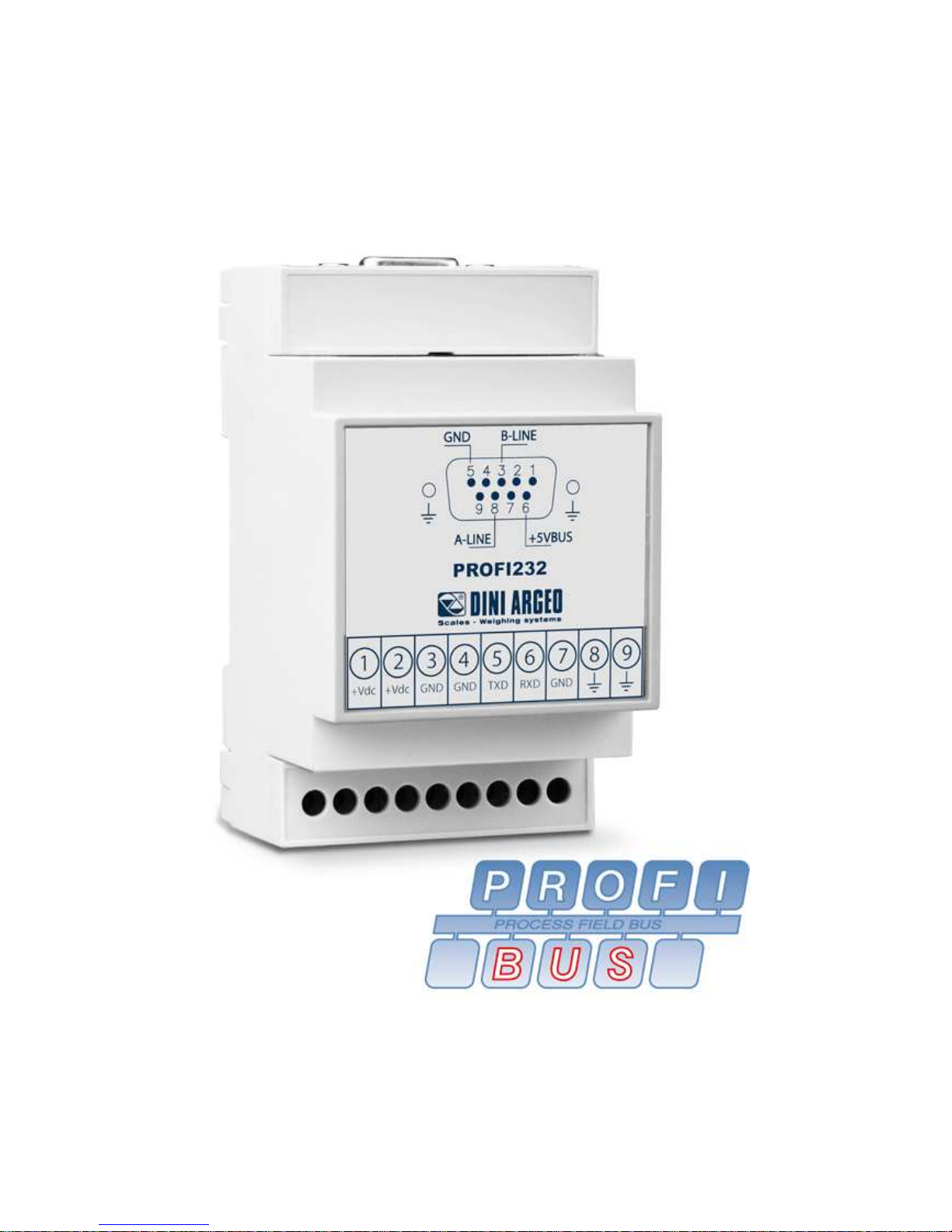
PROFIBUS INTERFACE
PROFI232
rel. 53160501
Page 2

2
INDEX
1. MAIN TECHNICAL SPECIFICATIONS ................................................ 3
2. DIMENSIONS........................................................................................ 3
3. EARTHING MODULE........................................................................... 4
4. CONNECTION SCHEMES ................................................................... 4
Page 3
3
1. MAIN TECHNICAL SPECIFICATIONS
POWER SUPPLY 12÷24 Vdc on terminal board or 5Vdc on internal AMP connector
ABSORPTION max 0,5 A
SERIAL RS232 on terminal board and internal AMP connector
FIELDBUS PROFIBUS-DP, female 9 pins connector
CASE Plastic console suitable for mounting on DIN bar or on the wall.
BOARD DIMENSION 50x87mm
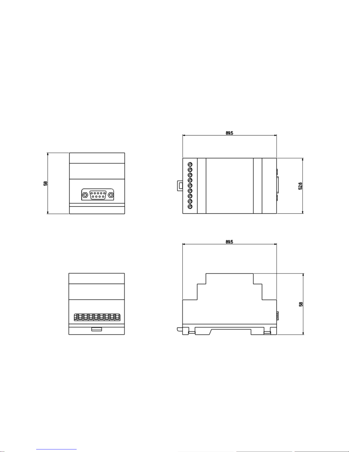
2. DIMENSIONS
Page 4
4
3. EARTHING MODULE
For the right earthing and the optimal functioning of the module, connect itself to the earth through copper
cables having at least a 16 mm2 cross-section.
To avoid possible side effects, the earth references of the connection and power supply cable of the
indicator and of the connected instrument must be at the same potential.
GENERAL NOTES:
- Use Earth plate of suitable length, in order to obtain a total resistance of earthing plant lower
than 1 Ω.
- One should check and remove, if necessary, the connection between the earth and the neutral
wire of the electrical installation.
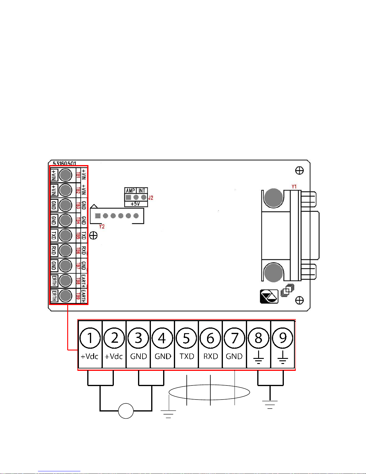
4. CONNECTION SCHEMES
+Vdc
+ -
▲
▼
Page 5
5
MEANING OF MOTHER BOARD TERMINAL BOARDS AND JUMPER
12÷24 Vdc POWER SUPPLY
1/2 (+Vdc) +12÷24 Vdc
3/4 (GND) 0Vdc (GND)
Note: the +Vdc power supply can be supplied either on the 1 or 2 clamp, and the GND on the 3 and 4
clamp.
RS232 SERIAL
5 (TXD) TX
6 (RXD) RX
7 (GND) GND
EARTHING
8/9 (ERTH) EARTH
Note: the earth cable can be connected either on the 8 or 9 clamp.
Y2 AMP
1 RX
2 TX
4 +5Vdc
6 GND
J2 JUMPER
- INT if the power supply is supplied from the terminal board.
- AMP if the power supply is supplied from the Y2 AMP connector.
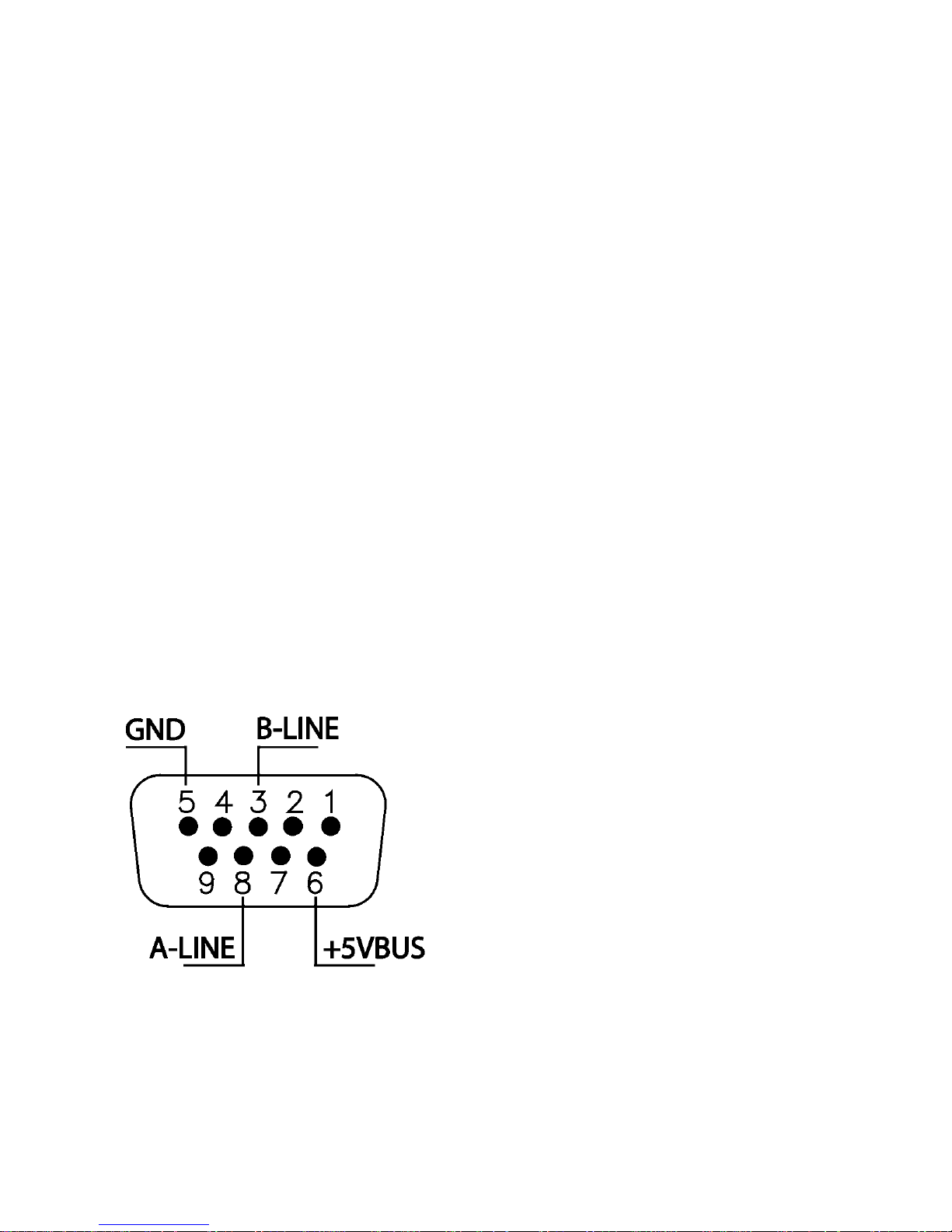
MEANING OF DB9 PROFIBUS CONNECTOR (Y1)
 Loading...