

Professional Sound Corporation Solice Operation Manual

Solice Audio Mixer
Operation Manual
For mixers with pcb version 3.0
Professional Sound Corp
Copyright 2009

Table of Contents:
ntroduction 4
I
Safety Warnings 4
Overview 4
Construction 5
INPUT SECTION:
Block Diagram 7
Input Panel View 8
Line / Microphone Input 9
Microphone Powering 9
Pre-Amplifiers 9
Gain Settings 9
High Pass Filters 10
Equalization 10
Limiters 10
Phase Reversal 10
Channel Assignment Switches 11
Channel Fader 12
Pre-Fade Listen Switch 12
Dedicated Line Outputs 12
Channel Ganging 13
Output Section panel View 14
2

Power Switch 14
Remote Roll 14
Reference Oscillator 15
Internal Slate Microphone 15
External Slate Microphone 16
Private Line 16
Comm System 16
Tape/Direct (Tape Returns) 17
M-S Stereo Decoding 17
Headphone Selections & Volume 17
Speaker Output 18
iPod Input 18
Peak Reading Meters 18
Main Output Faders 19
Rear Panel View 19
Main XLR Outputs 19
External Power Connection 19
Multi-Pin Connection 20
Specifications 21
Mixer Connector Pin Outs 22
RoHS 25
CE Mark 26
Warranty 27
3

Introduction
Thank you for purchasing the Professional Sound Corporation Solice Portable
Audio Mixer. The Solice Mixer is the result of our desire to provide you with a
comprehensive, yet simple to use portable mixer. This mixer has been designed
to handle multi-camera shots as well as multi-track recording. The Solice Mixer
provides extreme flexibility in signal routing, very high quality audio and field
friendly ergonomics in a compact, robust package. This new mixer design is the
result of several years work in developing our latest audio circuitry. Many of the
Solice’s design ideas came from you, our customers. We hope you will enjoy
using your Solice Audio Mixer for years to come.
Safety Warnings
The Solice Audio Mixer has been designed to be inherently safe to use. It
operates from low voltage DC only. The design complies with all current safety,
environmental and RF emission regulations. The safe use of this product is
determined primarily by the user. Please read and understand this entire user’s
manual before using your new Solice Mixer. Proper cabling is a must in, on and
around film and television production sets. Please always maintain proper and
safe headphone monitoring levels. If improperly used, this mixer can output
headphone levels that may result in permanent hearing loss. The owner and/or
user are to determine safe operating levels and maintain these levels at all times.
Professional Sound Corp, it’s owners, officers and employees accept no
responsibility for misuse of this mixer, whether intentional or not that may result
in personal injury and/or property damage. In addition, PSC reserves the right to
be held harmless for any liability caused by the use of this mixer with any other
equipment.
Overview
The Solice Portable Audio Mixer provides eight inputs each offering the following
comprehensive list of features:
• Precision, Super Low Noise Pre-amplifier developed by PSC
• Switchable Line or Microphone Input levels
• Phase Reversal
• Peak Detecting, Fast Acting Limiting
• 12T or 48PH Microphone Powering
• Fully Variable Pre-Amp Gain
• Fully Variable High Pass Filter
• Pan Pot for Assignment to Outputs 1 & 2
• Pre-Fade Listen
• Both Pre-Fader and Post Fader Channel Meters
• Pre-Fader or Post Fader Signals can be Individually Routed to any Output
Buss.
4

The Solice Mixer also provides a host of output capabilities:
• 8 main Balanced Outputs on Full Size XLR’s
• Peak Reading, Sun Light Readable LED Meters
• Slate Microphone
• Reference Tone Oscillator
• Tape Returns
• Stereo, M-s Decoding and Mono headphone Selections
• Separate Headphone Feeds For 2 Booms and 1 Director
• Private Line Function
• Duplex Boom Communication
• Little Lite BNC Jack
• Remote Roll Function
Construction
The Solice Mixer’s chassis forms a solid foundation for the mixer’s electronics.
The chassis is precision laser cut from sheet aircraft grade aluminum using a
state of the art laser made in Sweden. Laser cutting of the aluminum results in
less distortion of the panel than traditional hole punching. The resulting panel is
then formed using automated CNC controlled press brakes. The structural side
panels (located behind the billet aluminum sides) are then hand TIG welded on a
heavy, flat surface table. The final chassis is re-checked for straightness and
measured to insure all dimensions are within design specification.
The finished chassis is then Chem film plated so that it will resist corrosion and
offer years of trouble free service. The final step is the application of the epoxy
powder coat paint. This “powder” painting process uses an electrical charge to
attract the paint to the surface of the mixer. It provides superior adhesion and is
an environmentally friendly process as it does not release toxic solvents into the
air.
All silk-screen lettering on the Solice Mixer is applied to the back side of tough
Lexan tm overlays. Printing the lettering and graphics on the back side of a clear
overlay provides years of wear free use. Your fingers only rub against the sturdy
surface of the clear Lexan rather than wearing the lettering off as happens with
standard top surface silk-screening. After years of use, if your Lexan overlays
begin to get scratched or damaged, they can be replaced to re-new the
appearance of your Solice mixer.
The aluminum side panels are milled from solid billets using a Fadel CNC milling
center. After milling and de-burring, they are chem. Film plated for corrosion
resistance and then given a two-stage powder coat consisting of metallic silver
followed by a clear blue. Please note that if you ever remove these side panels,
5

you must use the same type and size screws when re-installing them. The use
of longer screws will interfere with the electronics within the mixer and cause
mixer damage.
The Solice mixer’s dust cover is formed from solid aluminum. It is easily
removed by simply pressing the two thumb buttons and sliding the cover towards
yourself.
6
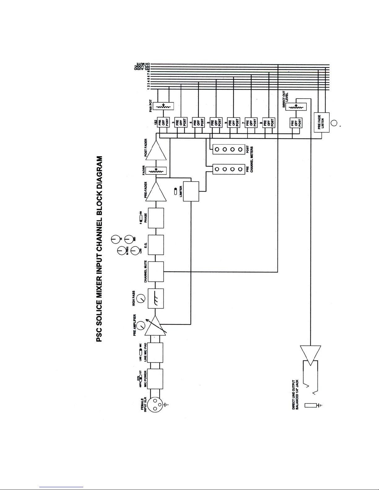
Block Diagram
7

Input Channel Panel View
CHANNEL METERS, PRE-FADER and POST-FADER
PRE-AMPLIFIER GAIN CONTROL
HIGH PASS FILTER
HIGH FREQUENCY E.Q.
MID FREQUENCY ADJUST (PARAMETRIC)
MID FREQUENCY E.Q.
LOW FREQUENCY E.Q.
PAN POT, CHANNEL LINE OUT LEVEL ADJUST
LINE/MIC INPUT SELECTION, MICROPHONE POWER
LIMITER, AUDIO PHASE REVERSAL
MIX 1 & 2 (PAN POT) SELECT, LINE OUT SELECT
MIX BUSS 3 SELECT, MIX BUSS 4 SELECT
MIX BUSS 5 SELECT, MIX BUSS 6 SELECT
MIX BUSS 7 SELECT, MIX BUSS 8 SELECT
PRE-FADE LISTEN SWITCH
8

Line or Microphone Input Levels
The Solice mixer has been designed and optimized to provide excellent preamplification of microphone level signals. In order to accept line level signals, an
input pad must be switched in. The Solice mixer contains switchable 40dB input
pads for this purpose. The switch is located on the front panel just below the Pan
pot. It is Labeled “L” for Line level signals and “M” for Microphone level signals.
Microphone Powering
The Solice Mixer is equipped to provide both 12T and 48PH microphone
powering to DIN standards. Each input channel has an individual power filter on
each of the 12T and 48PH power lines. This provides isolation between input
channels and helps keep the noise floor down when using powered
microphones. 12T microphone powering should only be used when powering
12T design microphones such as Sennheiser 416T. 48PH microphone
powering should only be used with 48PH microphones. When using dynamic
style microphones, the microphone powering should be switched off. You should
also turn off the microphone powering when using wireless receivers.
Pre-Amplifiers
The Pre-amplifiers used in the Solice Mixer were originally designed for our
Miranda Mixer. This design is the result of many engineering hours. This new
super low-noise design uses the latest in high performance semiconductors. The
semiconductors used in the pre-amplifier design offer impressive specifications
while consuming reasonable amounts of power. The fully variable gain structure
of the pre-amplifiers allows for gain changes on the fly. You no longer have to
worry about those coarse “stepped” gain changes found in other mixer designs.
The rotary gain control offers 55dB of adjustment range for extreme flexibility.
This allows the Solice mixer to work with low gain Dynamic microphones as well
as high gain condenser microphones.
Gain Setting
Because the Solice Mixer is equipped with both Pre-fader and Post-fader input
channel meters you can easily adjust both pre-amplifier gain and channel fader
settings quickly and easily. The Pre-fader meter can be used to properly set the
pre-amplifier gain. Simply adjust the gain setting until the meter occasional
“peaks” to the top “0” LED. Once set, you can mix without worry as you have
approximately 18dB of additional headroom in the pre-amplifier before clipping
occurs. The Post-fader meter can be used when routing post-fader audio to the
direct line output for multi-track recording. We believe that these two small
meters will be very helpful in your mixing endeavors.
9
 Loading...