

Page 1
®
®
TURNING ROLLS
00338OG091207
WARNINGS, SAFEGUARDS
&
OPERATING INSTRUCTIONS
Page 2
Warnings and Safeguards for
®
®
Welding and Cutting Operations
IMPORTANT - Protect yourself and others! Remember that safety depends on you. The operator, supervisor, and helper must read and
understand all warning and safety information provided in these instructions. Serious injury or death could result if welding equipment is not
properly installed, used and maintained. Training and proper supervision are most important for a safe work place. Installation, operation,
repair work, and maintenance must be preformed by qualified personnel. Retain these instructions for future use.
ELECTRICAL SHOCK CAN CAUSE INJURY OR DEATH
Electrical equipment must be installed and maintained in accordance with the National Electrical Code, NFPA 70, and all local codes. Maintain Mig-Guns,
Electrode Holders, Tig Torches, Plasma Torches, Work Clamp, Welding Cable, and Welding Machines in good, safe operating condition. Replace worn or
damaged insulation. Do not try to repair or service equipment while the power is still on. Do not service or repair equipment unless you are trained and
qualified to do so. The Electrode and Work (or Ground) circuits are electrically “HOT” when equipment power is on. At no time should you touch the
Electrode and Electrical Ground at the same time with bare skin or wet clothing while the power is on. Insulate yourself from work and ground using dry insulation.
When welding in damp locations make certain the insulation is large enough to cover your full area of physical contact with work and ground. Ground the work (metal
to be welded) to a good electrical earth ground. Keep gas cylinders, chains, wire ropes, hoists, cranes, and elevators away from any par t of the electrical path.
Always be sure the work cable makes a good electrical connection with the metal being welded. Occasionally check all ground connections to determine if they are
mechanically strong and electrically adequate for the current required. The ground connection should be as close as possible to the area being welded. Never touch
electrically “HOT” parts of electrode holders connected to two welding power sources at the same time. The voltage between the two can be the total of the open
circuit voltage of both power sources. When the welding or cutting process requires values of open circuit voltages in alternating current machines higher than 80
volts, and direct current machines higher than 100 volts, adequate insulation or other means must be provided to prevent the operator from making accidental contact
with the high voltage. The use of reliable automatic controls for reducing no load voltage is recommended to reduce shock hazard. When not welding for any
substantial period of time, make certain that no par t of the electrode circuit will accidentally make contact with the work or ground. Never immerse Mig-Guns,
Electrode Holders, Tig Torches, Plasma Torches, or Electrodes in water for cooling.
REFERENCES: See Safety and Operating References A,F,H, and I.
SMOKE, FUMES, AND GASES CAN BE DANGEROUS TO YOUR HEALTH
Keep smoke, fumes, and gases from your breathing zone and the general area. Smoke, fumes, and gases from the welding or cutting process are of
various types and strengths, depending on the kind of base metal being welded on. To ensure your safety, do not breathe these fumes or gases.
Ventilation must be adequate to remove smoke, fumes, and gases during the welding procedure to protect operators and others in the immediate area.
Do not weld in locations where chlorinated hydrocarbon vapors are coming from degreasing, cleaning, or spraying operations. Vapors of chlorinated solvents can form
the toxic gas “phosgene” when exposed to ultraviolet radiation from an electric arc. All solvents, degreasers, and potential sources of these vapors must be removed
from the welding area. Shielding gases used for arc welding can displace air and cause injury or death. Fumes produced by welding or cutting, especially in confined
areas, can cause discomfort and physical harm if inhaled over an extended period of time.
Always provide adequate ventilation in the welding and cutting area to insure breathing air is safe. Use air-supplied respirators if ventilation is not adequate to remove
all fumes and gases. Never Ventilate with Oxygen, because oxygen supports and vigorously accelerates fire.
REFERENCES: See Safety and Operating References A,B,C,H, and I.
HOT PARTS
Hot parts can cause serious burns. The area at and near the work being welded should be handled with proper gloves. Proper clothing should be worn
to prevent spatter or chipped slag from causing burns. Never pick up welded material until it has properly cooled.
REFERENCES: See Safety and Operating References A, B, H, & I.
MOVING PARTS MAY CAUSE INJURY
Have only qualified people remove guards or covers for performing maintenance and troubleshooting. Moving par ts such as cooling fans can maim
fingers or hands and catch loose clothing. Keep tools, hands, hair and clothing away from moving parts. Be sure to reinstall all panels and guards before
operating equipment.
FALLING EQUIPMENT
Lift only the unit to be moved without any running gear, accessories or gas cylinders that may be attached to it. Use equipment of a proper size to lift
and move the unit. Falling equipment can cause personal injury and equipment damage.
REFERENCES: See Safety and Operating References A, B, H, & I.
Safety and Operating References
A) ANSI Z49.1, “Safety in Welding and Cutting”
B) ANSI Z87.1, “Practice for Occupational and Educational Eye and Face Protection”
C) ANSI Z88.2, “Standard Practice for Respiratory Protection”
ANSI: American National Standard Institute, 1430 Broadway, New York, NY 10018
D) ANSI F4.1, “Recommended Safe Practices for Welding and Cutting Containers”
AWS: The American Welding Society, P.O. Box 351040, 550 NW Lejeune Rd., Miami, FL 33135
E) NFPA 51B, “Fire Prevention in Cutting and Welding Processes”
F) NFPA-70, “National Electrical Code”
NFPA: National Fire Protection Association, Batterymarch Park, Quincy, MA 02269
G) CGA P-1, “Precautions for Safe Handling of Compressed Gases in Cylinders”
CGA: Compressed Gas Association, 1235 Jefferson Davis Hwy., Arlington, Va 22202
H) Code of Federal Regulations (OSHA) 29 CFR 1910
US: U.S. Government Printing Office, Washington, DC 20402
I) CSA Standard W117.2, “Safety in Welding, Cutting and Allied Processes”
CSA: Canadian Standards Association, 178 Rexdale Blvd., Rexdale, Ontario, Canada M9W 1R3
Page 3
®
®
LIMITED WARRANTY: Subject to the terms and conditions hereof, PROFAX, Pearland, TX warrants its products to be free from defects in
workmanship and material at the time of delivery by PROFAX.
PROFAX will honor warranty claims on products as a result of failure from defect for a time period of 90 days from the date of sale to the
original user. Upon return of the merchandise at the user’s expense, PROFAX reserves the right to either repair or replace as necessary. This
is the only warranty either expressed or implied covering our products.
Warranty
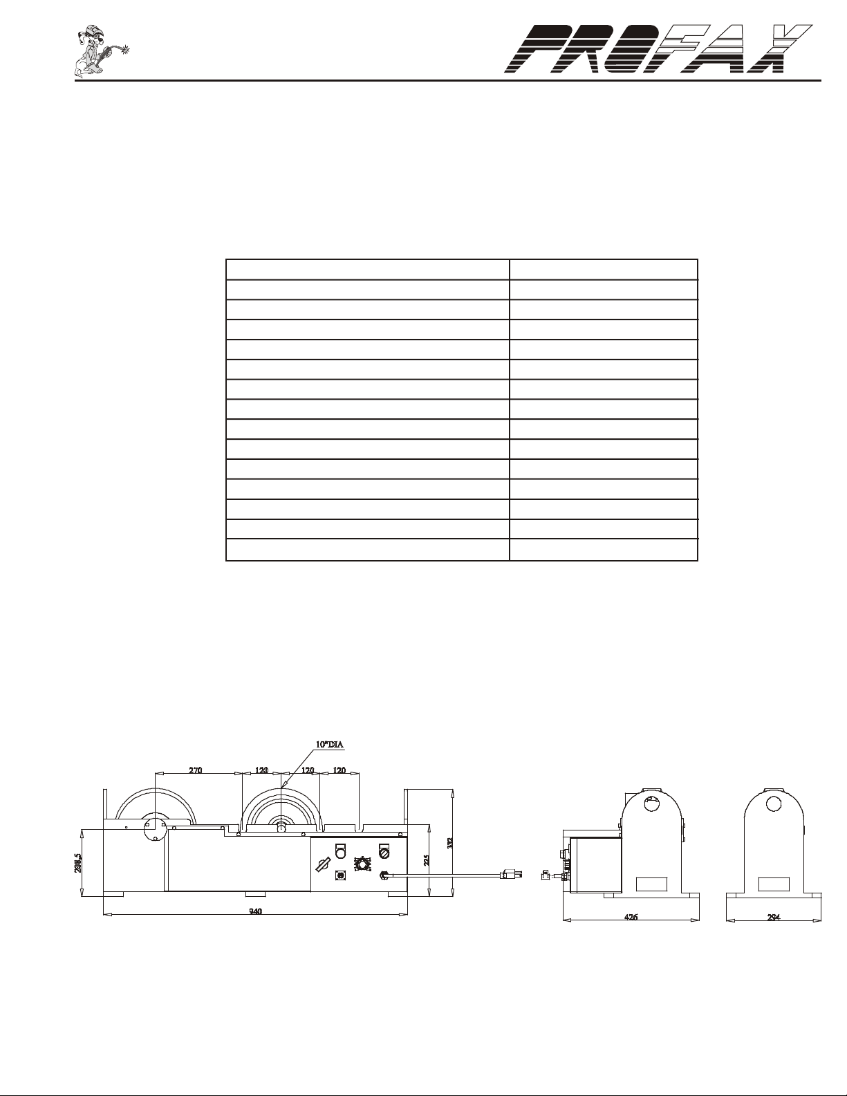
Specifications:
Total Weight Capacity, Per Set 5000
Motor, (Horsepower) 1/8
Power Requirement, (Volts/Amps) 110V @ 10 amps
Rotation Speed Range, (RPM) 0 - 4
Max. Work Diameter, (in.) 48”
Min. Work Diameter, (in.) 4”
Wheel Diameter, (in.) 10”
Wheel Width, (in.) 3”
Wheel Center to Center Spacing, (in.) 10-5/8” - 24-3/4”
Height to Top of Wheel, (in.) 13-1/4”
Power Unit Length, (in.) 37”
Power Unit Width, (in.) 18-1/8”
Idler Unit Length, (in.) 37”
Idler Unit Width, (in.) 11-5/8”
Shipping Weight Power & Idler Unit, (Lbs.) 430
Dimensions:
Figure No. 1 Dimensional Drawings
1i
Page 4

TR-5000 General
®
®
Operating Instructions
The PROFAX Turning Roll is designed for light loads, with a maximum load of 2500 lbs. per roll or 5000 lbs. per set.
Tube or vessel work piece sizes are from a minimum of 4” dia. to a maximum of 48” dia.
All mounting surfaces must be level and flat.
CAUTION! OVERLOADING of the turn rolls can cause
90°
slippage and damage to the wheels and drive components.
Make sure that the work piece does not exceed a maximum
of 5000 lbs.
Vessel or Pipe
Center Line
C
90°
D
AXY
Floor must be
Level and Flat
Figure No. 2 Turning Roll Alignment
Turning roll alignment is shown in figure 2. It is important that the distances of the turning roll axles from the mounting surface (X, Y, A, & B)
are the same for all axles. The rolls of the idler unit must be parallel to the rolls of the power unit (see dimensions C=D). Also the rolls must
be 90 degrees to the center line of the vessel or pipe that is to be turned. If any of the above are incorrect the vessel or pipe will creep off in
one direction or the other. Although it is almost impossible to obtain perfect alignment, with care, creeping can be held to a minimum.
Keeping in mind that very few cylinders are perfectly round, the irregularities of the cylinder will cause it to creep in one direction or the other.
This can cause a dangerous condition if not monitored closely. Be sure to rotate a cylinder a number of times while closely monitoring its
creep before starting a weld procedure.
B
Warning! Use equipment of a proper size to lift and/or move the weldment onto the turning rolls. Falling equipment can cause personal injury
and/or equipment damage.
Page 5

®
®
Control Panel & Wiring Diagram
1
2 3
1. Power On: Indicate of power.
POWER ON
SPEED
0FF ON
POWER
2. Speed Control: Provides control of rotation speed from
0%(0 RPM) to 100%(8 RPM).
3. Power ON/OFF: Power Switch “ON” or “OFF”
6
4. Foot Switch: Plug-in for the foot switch to start and stop the rotation.
FOOT SWITCH
POWER IN
AC110V
5. Power in
6. Fuse
4
5
CAUTION! - Switching rotation direction before coming to a complete
stop may damage motor and/or gear box voiding warranty.
Maintenance
The turning rolls require little maintenance other than periodical removal of spatter and dirt. Inspect the turning rolls periodically for nicks or
gouges in the rubber wheels. Replace wheels when damaged. A damaged wheel can cause erratic and/or unstable movement of the work
piece. Proper adjustment of drive roll should be maintained to prevent wheel slippage.
Wiring Schematic
Power
10A
L1
F1
SW1
GND
L2
Line voltage is 115VAC
for the TR-5000 and 220V
for the TR-5000-2
CR1
+A
8
19
A
PCB
F3
2120
T1
F
N
I
O
L
I
T
S
E
E
R
5
6
L1
L2
-A
+F
-F
7
CR2
CR2
8
CR1
8
CR1
13
I
CR2
14
11
12
9
CR1
R
1
CR2
M
10
CT1
R2
AC
5
24VAC
+
SR1
23
6
AC
P
1A
F2
FORWARD
CR2
RC1
5K
REVERSE
CR1
26
CR1
25 24
1 4 2
0
CR2
28
27
R
F
REMOTE
FOOT SWITCH
Service or repair of this unit must be done by qualified personnel only.
Warning! Before performing any maintenance on this control circuit disconnect the unit from any power supply.
32
Page 6

®
®
TR-5000 Parts List
3
4
11
5
12
2
1
6
7
9
8
5
12
NO. PROFAX DESCRIPTION
1. PX9933 Motor Cover
2. PX9934 Gear Box
3. PX9935 Gear Cover
4. PX9936 Power Wheel Gear
5. PX9962 Roller Wheel
6. PX9963 Pinion Gear
7. PX9964 Motor
TROUBLE SHOOTING
PROBLEM POSSIBLE CAUSE SOLUTION
1. No power 1. Check power supply for 115VAC 50/60Hz.
Indicator Light Fails to light 2. Fuse blown 2. Check and replace fuse.
3. Faulty indicator light 3. Check and replace indicator light.
4. Faulty power switch 4. Check and replace power switch.
1. Faulty PC board 1. Check and replace control box (see item 1 below).
Fuse blown 2. Faulty motor 2. Check and replace motor.
3. Faulty or bad transformer 3. Check and replace control box (see item 1 below).
1. Faulty PC board 1. Voltage to motor should vary from 0 to 90VDC in relation to the
Power roll fails to turn 2. Faulty motor 2. Check and replace motor.
3. Faulty forward/off/reverse switch 3. Check to see if switch is in correct position. Must be in either
NO. PROFAX DESCRIPTION
8. PX9965 Control Box
9. PXCFS-404 Foot Control Switch
10. PX9967 Fuse, Main Power 10A
11. PX7029 Power Wheel
12. PX7030 Idler Wheel Shaft
13. PX9983 PC Board Fuse 8A
speed control. If output is erratic or non-existing replace control box.
forward or reverse position to run. Test switch continuity.
4
Page 7

®
®
Wheel Spacing Selection Chart
WHEEL SETTING PIPE DIAMETER
A (Narrowest) Up to 18”
B 20” - 28”
C 30” - 40”
D (Widest) 42” - 48”
Daily Maintenance
*NOTE: INSPECT & REPAIR BEFORE OPERATION.
• Inspect table ground for proper ground tension against table. (Positioners)
• Check oil level in gear cases & fill if necessary. (WP-500/WP-1000/WP-2000)
• Inspect foot pedal and/or pendant for proper operation.
• Test limit switches if applicable.
• Test operation of power switch and/or emergency stop button.
• Check for any broken wires, loose connections, worn parts or damages before operation.
• Apply grease to all gears and grease fittings. (Weekly)
Page 8

 Loading...