

Page 1
®
®
Owner’s Manual
00110OG011905
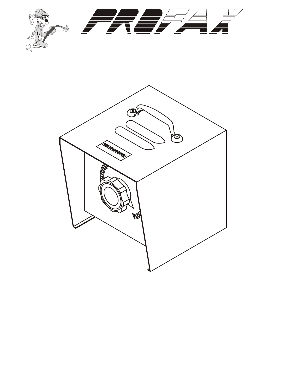
MHC-3 & MHC-3GD34A
REMOTE AMPERAGE CONTROLS
®
FOR MILLER WELDING POWER SOURCES
Note: Please read and understand the entire contents of this manual, with direct attention on the safety
material throughout this manual. This manual was intended for use by trained and qualified persons
to install, operate and/or service this unit. DO NOT allow untrained personnel to install, operate or
service this unit. Call your welding supply distributor if you do not fully understand these instructions.
Page 2
®
SAFETY
WARNING! Read and understand all safety messages in this and the welding power source owner's manual.
ELECTRIC SHOCK can kill.
• Do not touch live electrical parts
• Keep all panels in place.
• Keep yourself insulated from the work
WELDING can cause fire and explosion.
• Do not weld on closed containers.
• Watch for fire
WARRANTY
LIMITED WARRANTY - Subject to the terms and conditions hereof,
PROFAX, Pearland, TX warrants it's products to be free from defects in
workmanship and material at the time of delivery by PROFAX.
PROFAX will honor warranty claims on products as a result of failure from
a defect for a time period as listed below for the particular product line,
from date of sale to the original user.
Consumable products manufacturered by PROFAX......................... 30 Days
Resale consumable products.................... Original Manufacturer's Warranty
Mig Guns, Flux Cored Guns, Spool Guns........................................ 90 Days
Arc Gouging Torches, Plasma, Tig Torches & CO2Heaters.............. 90 Days
Remote Fingertip, Hand/Foot Controls............................................ 90 Days
Voltage Controls & Spool Guns...................................................... 90 Days
Spool Gun Controls....................................................................... 1 Year
Welding Power Sources & Wire Feeders......................................... 3 Year
Shelf Life Before WARRANTY Starts ........................................... 1 Year
Upon return of the merchandise at user's expense, PROFAX reserves the
right to either repair or replace as necessary.
This is the only warranty either expressed or implied covering
PROFAX products.
SMOKE, FUMES AND GASES can be
hazardous to your health.
• Keep head away from fumes and smoke.
• Ventilate work area
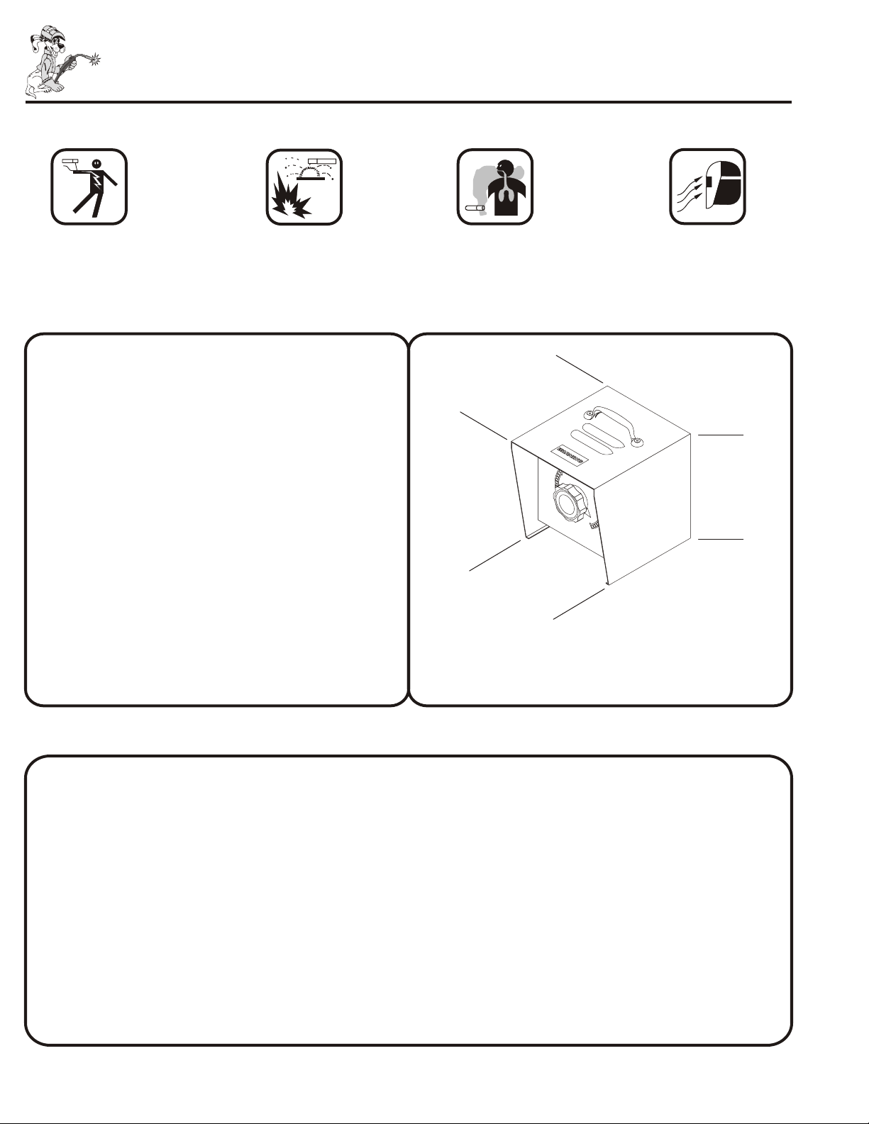
DIMENSIONS
D
W
HEIGHT 9 in. (229 mm )
WIDTH 7 in. (178 mm )
DEPTH 8 in. (203 mm )
ARC RAYS can burn eyes and skin.
• Wear correct body protection
• Wear welding helmet with filter.
H
INSTALLATION
WARNING! Electric Shock can kill.
• Do not touch live electrical parts.
• Shut off welding power source and disconnect all electrical power.
• Shut off engine before making electrical connections.
• Keep all panels securely in place.
CAUTION! Incorrect installation can damage unit.
• Double check installation instructions
1. Turn off welding power source or stop engine on welding generator.
2. TWISTLOCK PLUG:
• Make connection by aligning plug to mating receptacle on power source, inserting plug into the receptacle
and turning clockwise as far as it will go.
3. If the power source has a Contactor Switch - place it into the STANDARD or PANEL position.
4. If the power source has a Current or Voltage control switch - place it in the REMOTE position.
1 2
Page 3

MAINTENANCE
1. Turn off engine and/or disconnect all electrical power before performing maintenance.
2. EVERYDAY:
• Turn control fully from 0 to 100 taking care not to force the control past it's stopping points.
3. EVERY 3 MONTHS:
• Inspect repair and/or replace any cracked parts or frayed cords.
• Replace any unreadable labels.
TROUBLESHOOTING
1. NO AMPERAGE OR VOLTAGE CONTROL
• Check switches and controls on power source for proper position.
Remote Contactor Switch ------------Standard position (contactor on)
Remote Current or Voltage Switch --- Remote position
• Check plug on hand control to see if it is connected properly to receptacle on power source.
• Check control, cord and plug for broken wires or parts.
2. NO OUTPUT
• Check weld output on welding power source or generator.
(see power source owners manual)
®
REMOTE HAND CONTROL SELECTION GUIDE
MODEL PART NO. LENGTH COMPATIBLE EQUIPMENT
MHC-3 MHC-3 No Cord Used on all MILLER equipment that has the 030-653
MHC-3-25 25ft. Cord (15 ohm) rheostat.
MHC-3-50 50ft. Cord 330, 340, & 360 ABP, CP750E, DIALARC HF, FC6E,
MHC-3-100 100ft. Cord MK IV EXPRESS , MK VIII -2, SR150, SR200, 300, 400, & 600,
MP30E, 45E, 65E & 75E, SRH222, 303, 333, 404, 555 & 666
MHC-3GD34A MHC-3GD34A No Cord Used on all MILLER engine drive equipment that uses
MHC-3GD34A-25 25ft. Cord the 605-960 (34 ohm) rheostat.
MHC-3GD34A-50 50ft. Cord BIG 20G , BIG 25D , BIG BLUE 250D, BIG BLUE 251D,
MHC-3GD34A-100 100ft. Cord BIG 40 , BIG 40 D, BIG D4, BIG BLUE 400D,
BIG BLUE 400D AIRPAK , WD-5, WILDCAT 350G & 350D
REMOTE MCGD-40A Remote facilities for installing the MHC-3GD34A remote hand
FACILITIES control onto MILLER engine driven power sources that have the
605-960 (34ohm) rheostat.
®®
Miller is the trademark of Miller Electric Mfg. Co.
®® ® ®
®® ®
®®
®
®
®®
®
®
WIRING DIAGRAMS
PX030-653 Rheostat
REAR VIEW
PX605-797
Twistlock Plug
REAR VIEW
PX 605-960 Rheostat
REAR VIEW
Silver
9328
Twistlock Plug
REAR VIEW
White
Green
Black
MHC-3
WH
X
Y
Green
Black
White
Brass
MHC-3GD34A
Page 4

ISOMETRIC EXPLODED PARTS VIEW
®
®
& REPLACEMENT PARTS
4
1
9
3
9
7
5
2
10
6
8
ITEM PART NO. DESCRIPTION MHC-3 MHC-3GD34A
1 PX030653 Rheostate - 15 ohm - 150 Watt 1
PX605960 Rheostate - 34 ohm - 300 Watt 1
2 LHCK Knob 1
MHCK Knob 1
3 MHT Top Cover 1 1
4 LMH Handle 1 1
5 7026 Strain Relief Assembly 1 1
6 9283 Cord - Size 14/3 (order by ft.) 1
9285 Cord - Size 12/3 (order by ft.) 1
7 LHB Base 1
MHB Base 1
8 PX605-797 Plug - Twistlock 1
9328 Plug - Twistlock 1
9 9142 Label - PROFAX 2
10 9300 Label - MHC-3 1
9303 Label - MHC-3GD34A 1
3
 Loading...