

Page 1
®
®
Owner’s Manual
30
20
10
50
40
0
MHC-14
OFF ON
CONTACTOR
50
MHC-23
60
70
80
90
100
60
70
80
90
100
40
30
20
10
0
OFF ON
CONTACTOR
9821
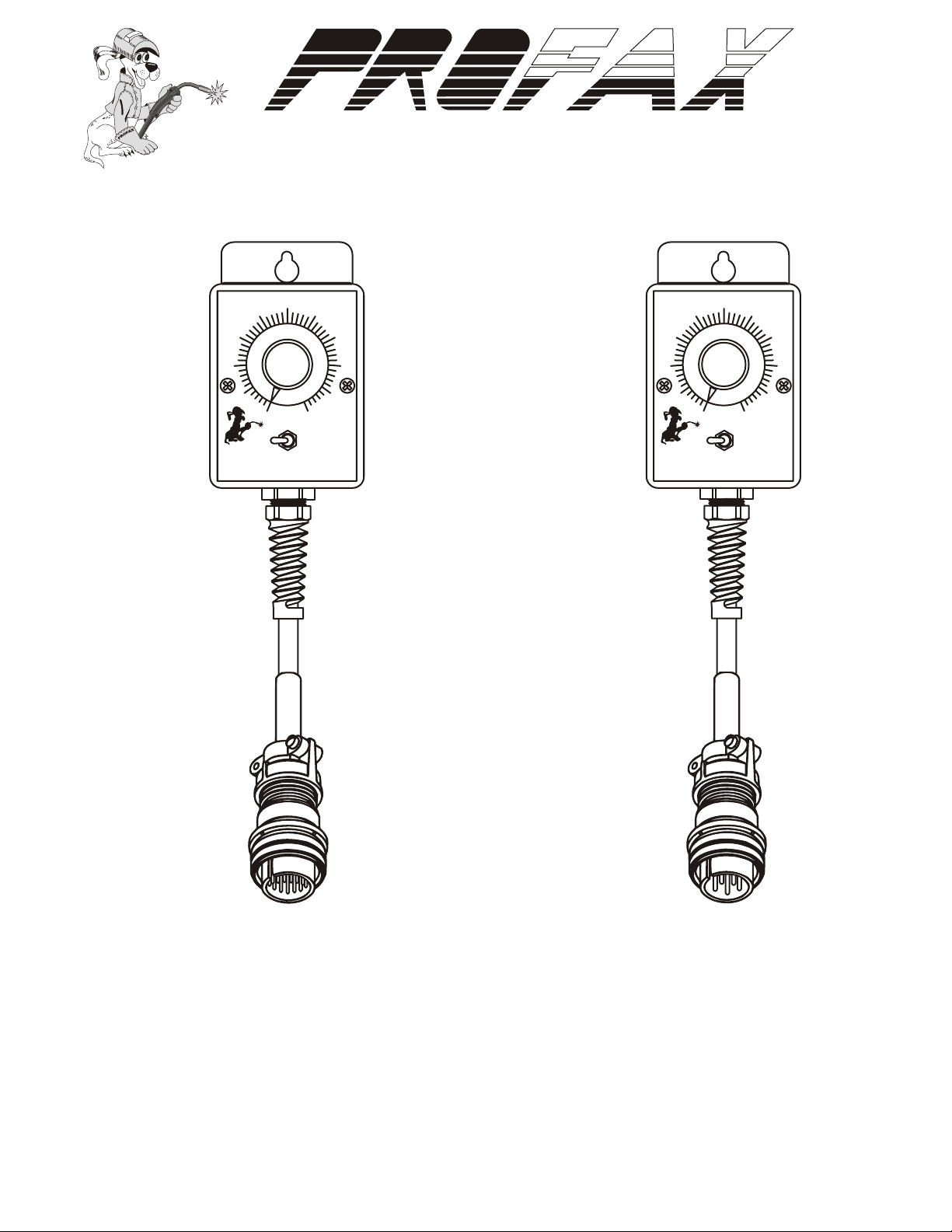
MHC-14 & MHC-23
REMOTE AMPERAGE & VOLTAGE CONTROLS
®
FOR MILLER WELDING POWER SOURCES
Note: Please read and understand the entire contents of this manual, with direct attention on the safety
material throughout this manual. This manual was intended for use by trained and qualified persons
to install, operate and/or service this unit. DO NOT allow untrained personnel to install, operate or
service this unit. Call your welding supply distributor if you do not fully understand these instructions.
Page 2
®
SAFETY
WARNING! Read and understand all safety messages in this and the welding power source owner's manual.
ELECTRIC SHOCK can kill.
• Do not touch live electrical parts
• Keep all panels in place.
• Keep yourself insulated from the work
WELDING can cause fire and explosion.
• Do not weld on closed containers.
• Watch for fire
WARRANTY
LIMITED WARRANTY - Subject to the terms and conditions hereof,
PROFAX, Pearland, TX warrants it's products to be free from defects in
workmanship and material at the time of delivery by PROFAX.
PROFAX will honor warranty claims on products as a result of failure from
a defect for a time period as listed below for the particular product line,
from date of sale to the original user.
Consumable products manufacturered by PROFAX......................... 30 Days
Resale consumable products.................... Original Manufacturer's Warranty
Mig Guns, Flux Cored Guns, Spool Guns........................................ 90 Days
Arc Gouging Torches, Plasma, Tig Torches & CO2 Heaters.............. 90 Days
Remote Fingertip, Hand/Foot Controls............................................ 90 Days
Voltage Controls & Spool Guns...................................................... 90 Days
Spool Gun Controls....................................................................... 1 Year
Welding Power Sources & Wire Feeders......................................... 3 Year
Shelf Life Before WARRANTY Starts ........................................... 1 Year
Upon return of the merchandise at user's expense, PROFAX reserves the
right to either repair or replace as necessary.
This is the only warranty either expressed or implied covering
PROFAX products.
SMOKE, FUMES AND GASES can be
hazardous to your health.
• Keep head away from fumes and smoke.
• Ventilate work area
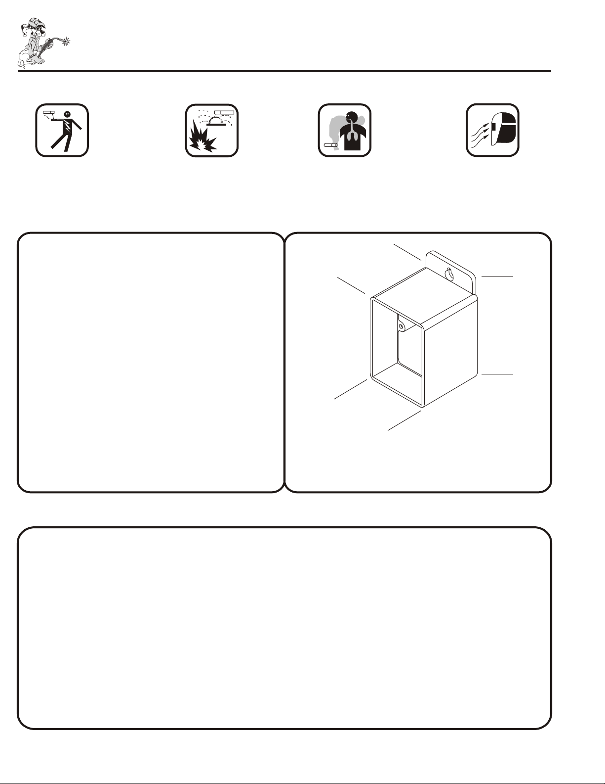
DIMENSIONS
D
W
HEIGHT 4.50 in. (114.30 mm )
WIDTH 2.80 in. (71.12 mm )
DEPTH 2.95 in. (74.93 mm )
WEIGHT 7 oz. (Box only)
ARC RAYS can burn eyes and skin.
• Wear correct body protection
• Wear welding helmet with filter.
H
INSTALLATION
WARNING! Electric Shock can kill.
• Do not touch live electrical parts.
• Shut off welding power source and disconnect all electrical power.
• Shut off engine before making electrical connections.
• Keep all panels securely in place.
CAUTION! Incorrect installation can damage unit.
• Double check installation instructions
1. Turn off welding power source or stop engine on welding generator.
2. AMPHENOL PLUG:
• Make connection by aligning keway to mating receptacle on power source, inserting plug and tighten by
threading collar clockwise onto receptacle.
3. If the power source has a Contactor Switch - place it into the STANDARD or PANEL position.
4. If the power source has a Current or Voltage control switch - place it in the REMOTE position.
1 2
Page 3

®
MAINTENANCE
1. Turn off engine and/or disconnect all electrical power before
performing maintenance.
2. EVERYDAY:
•Turn control fully from 0 to 100 taking care not to force the
control past it's stopping points.
3. EVERY 3 MONTHS:
•Inspect repair and/or replace any cracked parts or frayed cords.
TROUBLESHOOTING
1. NO AMPERAGE OR VOLTAGE CONTROL
• Check switches & controls on power source for proper position.
Remote Contactor Switch --- Standard position (contactor on)
Remote Current or Voltage Switch --- Remote position
• Check plug on hand control to see if it is connected properly to
receptacle on power source.
• Check control, cord and plug for broken wires or parts.
•Replace any unreadable labels.
2. NO OUTPUT
• Check weld output on welding power source or generator.
(see power source owners manual)
REMOTE HAND CONTROL SELECTION GUIDE
MODEL PART NO. LENGTH COMPATIBLE EQUIPMENT
MHC-23 MHC-23 No Cord Used on MILLER equipment that has the 5 pin remote
MHC-23-25 25ft. Cord control receptacle.
MHC-23-50 50ft. Cord 330ST AIRCRAFTER , BIG 30 DIESEL , BIG 30A DIESEL ,
MHC-23-100 100ft. Cord BIG 40G , BIG 40 DIESEL , BIG 50 DIESEL , CS450
®®®
DELTAWELD 450, 451, 650 & 651, DIMEMSION 400,
GOLDSTAR 300SS, 400SS, 500SS & 600SS, MAXSTAR 150,
SQUAREWAVE 1000, SYNCROWAVE 250, 300, 350 & 500
MHC-14 MHC-14 No Cord Used on MILLER equipment that has the 14 pin remote
MHC-14-25 25ft. Cord control receptacle.
MHC-14-50 50ft. Cord BIG 30A DIESEL , BIG 40G , BIG 40 DIESEL , BIG 50 DIESEL ,
MHC-14-100 100ft. Cord BIG BLUE 600D, CP/CC1500, DELTAWELD 300, 302, 402, 451,
452, 602, 651, 652 & 852, DIMENSION 302, 372, 400, 452, 562,
650, 652 & 812, GOLDSTAR 300SS, 400SS, 500SS & 600SS,
MK VI MAXSTAR 91, 152 & 175, MAXTRON 300 & 450,
®®®
METRO 250D & 300DXQ, MILLER AIRPAK , SHOPMASTER 300,
SYNCROWAVE 250, 351, 500 & 500P, TRAILBLAZER 250G &
250D, XMT 200, 300 & 304
302, 402, 502, BIG BLUE TURBO, CST 250, CST400,
DIMENSION 1000, DYNASTY 200SD, 200DX, 300SD & 300DX
GOLDSTAR 302, 452, 652, DELTA FAB, INVISION 354MP,
456MP, INVISION 456P, LEGEND 301G, MAXSTAR 200SD,
200DX & 200STR, MILLER DU-OP, PIPE PRO 304, PRO 350,
SYNCROWAVE 180SD, 250DX & 350 LX,
TRAIL BLAZER 301G & 301D, XMT 456
®®
Miller is the trademark of Miller Electric Mfg. Co.
WIRING DIAGRAMS
REAR VIEW
1K
Potentiometer
MHC-14
14 Pin Amphenol Plug
REAR VIEW
Red
A
J
I
K
B
C
N
L
D
H
M
G
E
F
®
®® ®
®®
®®
®®
®
®®®®
®®
®
®
®®
®®
®®®
®®
®®®
®® ®
®
®
AEROWAVE ,ALT 304, BIG BLUE
®
®
MHC-23
REAR VIEW
1K
Potentiometer
5 Pin Amphenol Plug
REAR VIEW
E
A
B
C
D
OFF
ON
Green
Brown
White
Black
OFF
ON
Red
Green
Brown
White
Black
Page 4

ISOMETRIC EXPLODED PARTS VIEW
®
®
6
& REPLACEMENT PARTS LIST
1
3
5
2
7
8
11
4
9
10
13
12
ITEM PART NO. DESCRIPTION MHC-14 MHC-23
1 9813 Potentiometer - 1K - 1T - 2W 1 1
2 9327 Tension Nut 1 1
3 9029 Potentiometer Insulator 1 1
4 9812 Base 1 1
5 9825 Dial Plate 1
9826 Dial Plate 1
6 9814 Knob 1 1
7 9816 Contactor Switch 1 1
8 R185SC Screw 2 2
9 9815 Strain Relief 1 1
10 9820 Cord - Size 18/5 (order by ft.) 1 1
11 9830 Label - CAUTION! 1 2
12 PX039273 Plug - 5 Pin 1
13 PX136961 Plug - 14 Pin 1
AVAILABLE THROUGH YOUR
WELDING SUPPLY DISTRIBUTOR
3
 Loading...