

MODEL AEC 200
SPOOL GUNS
AEC 200
00019OG1106
OPERATION and PARTS MANUAL
Available Through your Welding Supply Distributor
®
Pearland, TX 77588-0898
Mailing:
P.O. Box 898
Shipping:
1603 North Main
Pearland, TX 77581-2803
®

®
®
P.O. Box 898 • Pearland, TX 77588-0898 • (281) 485-6258
Table of Contents
CONTENT PAGE
Warnings, First Aid & Safety References ............................................................................... 1-2
Description and Installation ................................................................................................... 3
Operation .............................................................................................................................. 4
Gun Selection, Duty Cycle, and Shipping Weight ................................................................... 5
Duty Cycle ............................................................................................................................ 5
Control Boxes & Diagrams ................................................................................................... 6-13
Spool Gun Wiring ................................................................................................................. 14-15
Control Box Wiring Schematics ............................................................................................ 15-16
Control Box Parts List .......................................................................................................... 17-18
Preweld Check List .............................................................................................................. 19
Shutting Down ..................................................................................................................... 19
Maintenance ........................................................................................................................ 19
Removal & Replacement Information ................................................................................... 20-21
AEC Consumables ............................................................................................................... 22-23
Parts Breakdown ................................................................................................................. 24
Part Numbers & Description ................................................................................................. 25
Rebuilt AEC 200 Welding Guns & Motors ............................................................................. 26
WARRANTY
LIMITED WARRANTY—Subject to the terms and conditions hereof, PROFAX, Pearland, Texas warrants its Model AEC 200 to be free
from defect on workmanship and material at the time of delivery by PROFAX.
PROFAX will honor warranty claims on this equipment that result from a failure due to a defect for a time period as listed below
beginning from date of sale to the original user.
All AEC Spool Guns — 90 days
All AEC Control Boxs — 1 year
Upon the return of this unit at users expense, PROFAX reserves the right to either repair or replace as necessary.
This is the only warranty either expressed or implied covering this unit.
CERTIFICATE OF QUALITY
This product was manufactured by PROFAX, Pearland, Texas using the highest quality of domestic components available.
Each unit is tested to meet all industry standards to the maximum.

WARNINGS & SAFEGUARDS FOR
WELDING & CUTTING OPERATIONS
Important - Protect yourself and others! Remember that safety depends on you.
The operator, supervisor, and helper must read and understand all warning and safety information provided in these
instructions and the power source manual used with this equipment. Serious injury or death could result if welding and
cutting equipment is not properly installed, used, and maintained.
Training and proper supervision are most important for a safe work place. Installation, operation, repair work, and
maintenance must be performed by qualified personnel. Retain these instructions for future use. Additional recommended
safety and operating information is referenced in each section.
ELECTRICAL SHOCK CAN CAUSE INJURY OR DEATH
Electrical equipment must be installed and maintained in accordance with the National Electrical Code,
NFPA 70, and all local codes. Maintain Mig-Guns, Electrode Holders, Tig Torches, Plasma Torches, Work
Clamp, Welding Cable, and Welding Machines in good, safe operating condition. Replace worn or damaged
insulation. Do not try to repair or service equipment while the power is still on. Do not service or repair
equipment unless you are trained and qualified to do so.
The Electrode and Work (or Ground) circuits are electrically “HOT” when equipment power is on. At no time should you
touch the Electrode and Electrical Ground at the same time with bare skin or wet clothing while the power in on. Insulate
yourself from work and ground using dry insulation. When welding in damp locations make certain the insulation is large
enough to cover your full area of physical contact with work and ground.
Ground the work (metal to be welded) to a good electrical earth ground. Keep gas cylinders, chains, wire ropes, hoists,
cranes, and elevators away from any part of the electrical path. Always be sure the work cable makes a good electrical
connection with the metal being welded. Occasionally check all ground connections to determine if they are mechanically
strong and electrically adequate for the current required. The ground connection should be as close as possible to the area
being welded.
Never touch electrically “HOT” parts of electrode holders connected to two welding power sources at the same time. The
voltage between the two can be the total of the open circuit voltage of both power sources. When the welding or cutting
process requires values of open circuit voltages in alternating current machines higher than 80 volts, and direct current
machines higher than 100 volts, adequate insulation or other means must be provided to prevent the operator from making
accidental contact with the high voltage. The use of reliable automatic controls for reducing no load voltage is recommended
to reduce shock hazard.
When not welding for any substantial period of time, make certain no par t of the electrode circuit is touching the work or
ground to prevent accidental contact. Never immerse Mig-Guns, Electrode Holders, Tig Torches, Plasma Torches, or
Electrodes in water for cooling.
REFERENCES: See Safety and Operating References A,F,H, and I.
SMOKE, FUMES, AND GASES CAN BE DANGEROUS TO YOUR HEALTH
Keep smoke, fumes, and gases from your breathing zone and the general area. Smoke, fumes, and gases
from the welding or cutting process are of various types and strengths, depending on the kind of base metal
being welded on. To ensure your safety, do not breath these fumes or gases. Ventilation must be adequate to
remove smoke, fumes, and gases during the welding procedure to protect operators and others in the immediate area.
Do not weld in locations where chlorinated hydrocarbon vapors are coming from degreasing, cleaning, or spraying
operations. Vapors of chlorinated solvents can form the toxic gas “phosgene” when exposed to ultraviolet radiation from an
electric arc. All solvents, degreasers, and potential sources of these vapors must be removed from the welding area.
Shielding gases used for arc welding can displace air and cause injury or death. Fumes produced by welding or cutting,
especially in confined areas, can cause discomfort and physical harm if inhaled over an extended period of time.
Always provide adequate ventilation in the welding and cutting area to insure breathing air is safe. Use air-supplied
respirators if ventilation is not adequate to remove all fumes and gases. Never Ventilate with Oxygen, because oxygen
supports and vigorously accelerates fire.
REFERENCES: See Safety and Operating References A,B,C,H, and I.
1

ARC RAYS, MOLTEN MATERIAL, AND SPARKS CAN CAUSE EYE AND SKIN INJURY
Always wear approved eye, ear, and body protection. Remove any and all combustible material from the
work area. Never attempt to weld or cut without a proper head shield, with proper lens, that conform to
federal guidelines. A number 12 to 14 shade filter lens provides the best protection from arc radiation. A
cover plate protects your eyes from sparks.
Protect other nearby personnel from arc rays and sparks. Use approved shielding curtains and appropriate goggles.
Warn them not to watch the arc or expose themselves to arc rays, sparks, or molten material.
Always wear protective clothing and gloves which will not allow skin to become exposed to arc rays, heat, or molten
material. Wear ear plugs to protect ears from sparks. Flammable hair preparations should not be used when welding or
cutting.
If possible, welding should be done in a booth that has been painted with an ultraviolet absorbing material such as zinc
oxide and a low reflective finish such as lamp black, or shall be enclosed with noncombustible screens similarly painted.
REFERENCES: See Safety and Operating References A,B,H, and I.
WELDING SPARKS CAN CAUSE FIRES AND EXPLOSIONS
Remove any and all combustible materials from the work area. If this is not possible, cover them to prevent
the welding sparks from starting a fire. Causes of fire and explosion are any combustibles reached by the
arc, flame, flying sparks, hot slag, or heated materials. Do not wear any gloves or clothing that has oil or a
fuel type material on it. Always have a properly working and OSHA approved Fire Extinguisher near and be sure everyone
has proper training in its use.
Do not weld, heat, or cut drums or containers that have held combustibles. All hollow spaces, cavities, and containers
should be vented prior to cutting, welding, or heating for they may explode. Make sure proper steps have been taken to
insure that venting procedures will not form flammable or toxic vapors from substances inside containers. Purging with inert
gas is recommended.
Use only inert gases or iner t gas mixes as required by the process. Special precautions should be used to prevent
hazardous situations when using compressed gas. Use of combustible compressed gases can cause explosions resulting in
personal injury or death. Never Use Oxygen for Cleaning or Purging.
Arcing against any compressed gas cylinder can cause cylinder damage or explosion. Read and follow the instructions on
compressed gas cylinders, Associated Equipment, and CEA Publication P-1, “Precautions for safe handling of compressed
gases in Cylinders” available from the Compressed Gas Association, 1235 Jefferson Davis Hwy, Arlington, Va. 22202.
REFERENCES: See Safety and Operating References A,D,E,F,G, and H.
SAFETY AND OPERATING REFERENCES
A) ANSI Z49.1, “Safety in Welding and Cutting”
B) ANSI Z87.1, “Practice for Occupational and Educational Eye and Face Protection”
C) ANSI Z88.2, “Standard Practice for Respiratory Protection”
ANSI: American National Standard Institute, 1430 Broadway, New York, NY 10018
D) AWS F4.1, “Recommended Safe Practices for Welding and Cutting Containers”
AWS: The American Welding Society, P.O. Box 351040, 550 NW Lejeune Rd., Miami, Fl 33135
E) NFPA 51B, “Fire Prevention in Cutting and Welding Processes”
F) NFPA-70, “National Electrical Code”
NFPA: National Fire Protection Association, Batterymarch Park, Quincy, MA 02269
G) CGA P-1, “Precautions for Safe Handling of Compressed Gases in Cylinders”
CGA: Compressed Gas Association, 1235 Jefferson Davis Hwy., Arlington, Va 22202
H) Code of Federal Regulations (OSHA) 29 CFR 1910
US: U.S. Government Printing Office, Washington, DC 20402
I) CSA Standard W117.2, “Safety in Welding, Cutting and Allied Processes”
CSA: Canadian Standards Association, 178 Rexdale Blvd., Rexdale, Ontario, Canada M9W 1R3

DESCRIPTION
The Model AEC 200 Welding Gun is a complete hand held wire feeder with a 50 ft. *cable/hose assembly. The
cable/hose assembly is designed for operator comfort and extends from the top rear of the welding gun.
*If needed cable/hose assemblies of a longer length are available.
The Model AEC 200 Welding Gun will feed .030" through 1/16" diameter aluminum wires and .030" through .045"
diameter hard wires. *See selection chart for proper motor ratio for wire size selected. Wire drive motors are
interchangeable in the gun to make it readily adaptable for large or small welding applications. Each standard model comes
complete with all of the parts necessary to weld with the wire diameter selected.
INSTALLATION
The Model AEC 200 Welding Gun should be connected to direct current (DC) reversed polarity (DC RP). The gun power
cable is connected to the positive (+) terminal on the welding power source or "GUN" terminal on the control box and the
negative (-) terminal of the welding power source is connected to the work piece through the work cable. If the welding
power source has a polarity switch, it should be set in the REVERSE polarity mode.
**IMPORTANT: When using power sources with high frequency, make certain high frequency is
turned OFF to avoid damage to the gun.
SAFETY
DISCONNECT ELECTRICAL POWER TO WELDING POWER SOURCE BEFORE ATTEMPTING TO MAKE ANY PRIMARY OR
SECONDARY CONNECTIONS. ELECTROCUTION MAY INJURE OR KILL.
32

OPERATION
The Model AEC 200 Welding Gun will operate on numerous manufacturers welding power sources and is driven by a 24
volt DC permanent magnet motor. The following should be taken into consideration when operating the AEC 200 Welding
Gun on your welding power source.
A.) Constant Voltage Power Sources (MIG)
1.) AEC 200 Welding Gun - will connect directly to a DC welding power source having the proper 24 volt
DC control circuit. (24 Volt terminal strip.)
2.) Model AEC 200-1 Control Box - For use with constant voltage welding power sources lacking the
necessary control circuit. This control box requires 115V AC 60 hz. input power and uses a step-down
transformer which is voltage rectified to provide the necessary 24 volts DC for the welding gun
control circuit and wire feed motor.
B.) Constant Current Power Sources. (DC Stick or DC Tig.)
1.) Model AEC 200-2 Control Box - for use with Constant Current DC welding power sources having
115V AC 60 hz auxilliary power available while welding or where external 115V AC can be utilized
near the welding power source during the welding operation. The 115V AC 60 hz. provides power to
a step-down transformer reducing the voltage to 24V AC which is rectified to 24V DC for the welding
gun control circuit and wire drive motor operation. As soon as the welding wire touches the work
piece a reaction, through a current relay, allows the wire drive motor to operate off of the arc voltage.
This is considered a *"HOT" start and wire will continue to feed if the gun trigger is released,
however, due to manual operation of the gas valve, the gun trigger must still be depressed for
shielding gas flow. To stop the welding process you must rapidly break the arc while releasing the
gun trigger to prevent excessive wire runout which may damage the drive motor.
*The welding gun and wire will be live ("HOT") even when not operating as long as the welding power
source is on unless an AEC 200 Contactor or internal machine contactor, is operated by the AEC 200-2
Control Box.
2.) Model AEC 200-C Contactor - designed to be used with the Model AEC 200-2 Control Box to provide
a "COLD" start when using the Model AEC 200 Gun on DC constant current welding power sources,
not having an internal contactor. It may also be used in any application requiring a welding contactor,
as long as operating parameters are observed. *See installation instructions when using Model
AEC 200-C Contactor.
3.) When using a DC Tig power source with contactor in machine, you may use the AEC 200-2 control
box and run an 18/2 conductor cord from the welding machine to the control box. This will provide
contactor control giving a "COLD" start. *See installation instructions when using Model AEC 200-2
Control Box. HIGH FREQUENCY should be in the OFF position when operating the AEC 200
Welding Gun or damage to the gun will result.
C.) Constant Current Stationary or Engine Driven Power Source. (DC Stick)
1.) Model AEC 200-3A Control Box - designed to be used with constant current DC welding power
sources, stationary or engine driven, for aluminum welding. A 250Amp contactor is built into the
control box to provide a "COLD" start. Either 115V AC or DC is required to operate the control
circuitry in this unit. Welder OPEN CIRCUIT VOLTAGE (OCV) is utilized by the AEC 200 Gun for
run in and the welding voltage also powers the wire drive motor while welding. An optically isolated
solid state relay is used in the gun trigger circuitry in order to isolate the operator from hazardous
voltages. *See installation instructions when using Model AEC 200-3A Contactor Control Box.

GUN SELECTION
The PROFAX AEC 200 Welding Gun is available in three separate component packages according to the welding wire size
and type required. The chart below gives PROFAX's recommendations.
THE SELECTION CHART
WIRE MOTOR GEAR MODEL NOZZLE CONTACT TUBE
SIZE TYPE RATIO NO. SIZE & LINER
0.030-3/64"(0.8mm) Aluminum 36:1 AEC 200-36 11/16" 3/64"(1.2mm)
3/64"(1.2mm) Aluminum 64:1 AEC 200-64 11/16" 3/64"(1.2mm)
0.035(0.9mm) Hard 81:1 AEC 200-81 11/16" 0.035(0.9mm)
0.030-3/64"(0.8mm) Aluminum 36:1 AEC 200-36P 11/16" 3/64"(1.2mm)
3/64"(1.2mm) Aluminum 64:1 AEC 200-64P 11/16" 3/64"(1.2mm)
0.035(0.9mm) Hard 81:1 AEC 200-81P 11/16" 0.035(0.9mm)
0.030-3/64"(0.8mm) Aluminum 36:1 AEC 200-36L 11/16" 3/64"(1.2mm)
The AEC-200L Spool Gun is a modified PROFAX Gun to direct connect to the ESAB (L-Tec ) MigMaster 250 and the ESAB Mig-28A
®® ®
Control Module. This comes with 30' cable hose assembly.
P = Gun with 10 Pin Amphenol Plug (Direct mount Spool Gun for Airco (ESAB ) 10 pin receptacle and PROFAX Power Sources)
L = Gun with 8 Pin Amphenol Plug (Direct mount Spool Gun for ESAB (L-Tec ) MigMaster 250. Comes complete w/30' cable hose assembly.)
®®
®®
DUTY CYCLE
MODEL AEC 200 RATINGS
Current
(D.C.R.P.) Duty Cycle* Gas
200 Amps 100% Argon or Helium
250 Amps 50% Argon or Helium
275 Amps 30% Argon or Helium
300 Amps 100% Carbon Dioxide
*Duty cycle based on 10-minute intervals.
SHIPPING WEIGHT 26 LBS. (11.8kg)
ORDER FROM YOUR WELDING DISTRIBUTOR
54
CONTROL BOXES
For use in connecting the AEC 200 Welding Gun to a constant voltage welding power source.
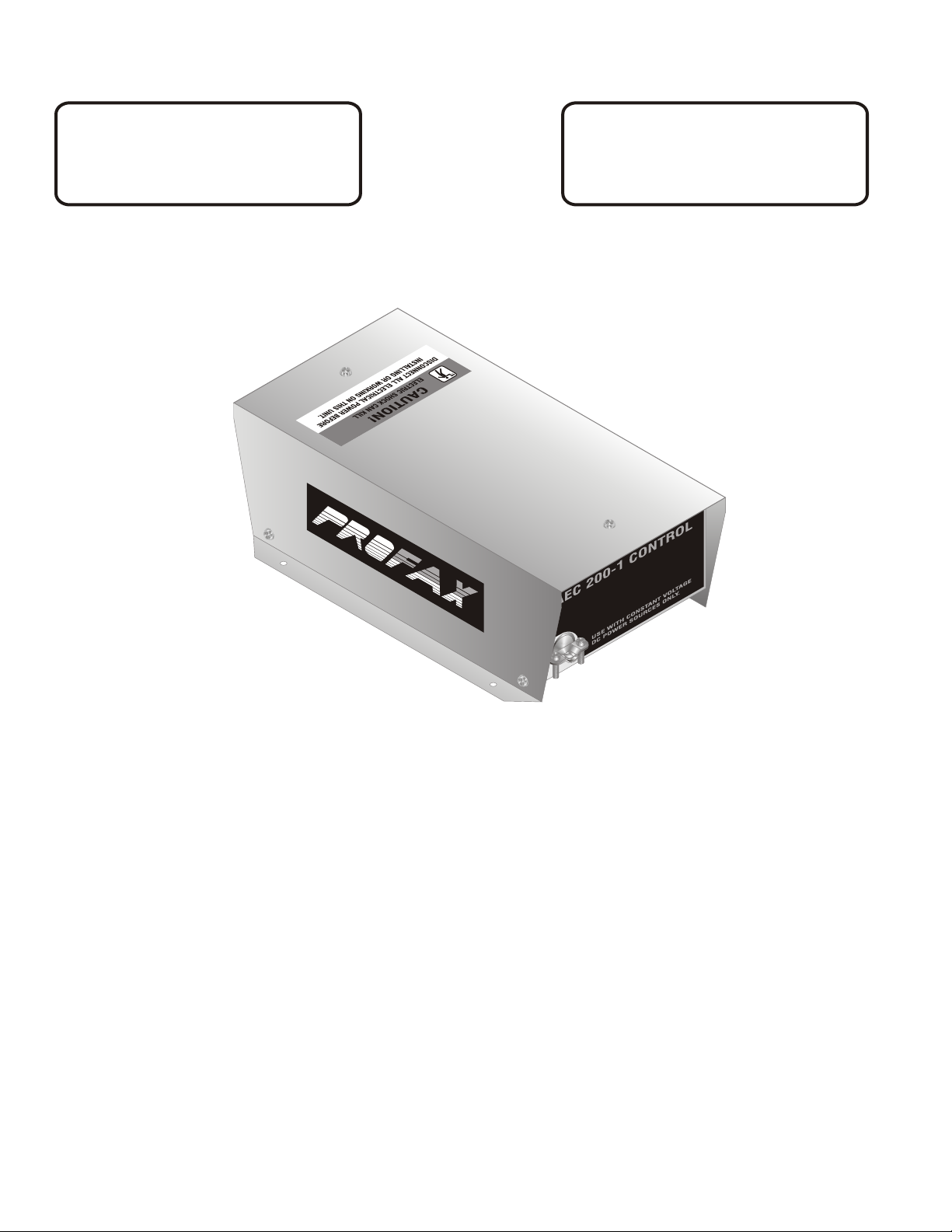
MODEL AEC 200-1
WARNING
Disconnect all electrical power before installation
of this control unit. Touching live electrical
parts can cause fatal shock.
CAUTION
Shut off engine before attempting any installation.
Moving parts and live electrical connections
can maim.
AEC 200-1
TO INSTALL:
1.) Remove top cover from control unit.
2.) Install the multi-conductor cord from the AEC 200 Welding Gun through the access hole in the front panel of
the control box and connect the numbered wires to the corresponding numbers on the 8 pole terminal
strip TS1.
3.) Connect the contactor control cord on the back of the control box to the contactor control
receptacle on the welding power source. (See note below).
4.) Connect the 115 volt A.C. power cord from the control box to a 115 volt A.C. power source.
5.) Replace top cover and tighten screws.
NOTE
Terminals 1 and 2 on the four pole terminal strip TS2 are for use with welding power sources requiring a normally open set of
contacts for power source contactor operation. This set of contacts will close when the gun switch is operated.
Terminals 3 and 4 on the four pole terminal strip are for use with welding power sources requiring 115 VAC to be supplied to the
power source for contactor operation.
This control box comes with the contactor control cord connected to terminals 1 and 2.
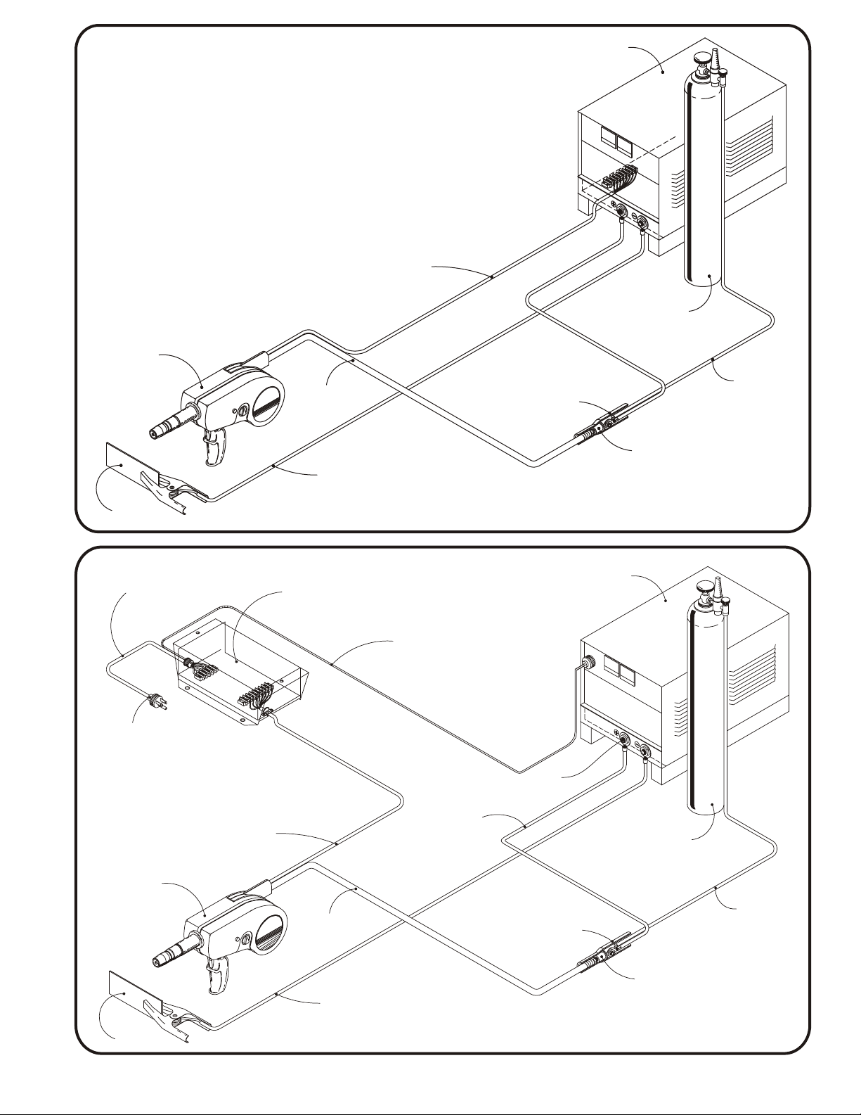
CONSTANT VOLTAGE POWER SOURCE WITH 24 VOLT STRIP
POWER
SOURCE
CABLE TO 24 VOLT
TERMINAL STRIP IN
POWER SUPPLY
MODEL
AEC 200
SPOOL GUN
GAS & WELDING
CABLE
WELDING CABLE
TO WORK
WORK
CONSTANT VOLTAGE POWER SOURCE WITH AEC 200-1
115 VOLT AC
POWER CABLE
MODEL
AEC 200-1
CONTROL
CONTACTOR CONTROL
CABLE TO CONTACTOR
CONTROL RECEPTACLE
ON POWER SOURCE
(see installation instructions)
POSITIVE
CABLE
BOOT
NEGATIVE
POWER
SOURCE
GAS CYL.
CONNECTION
BLOCK
HOSE TO GAS
SUPPLY
115 VOLT AC
*PLUG NOT INCLUDED
MODEL
AEC 200
SPOOL GUN
WORK
MULTI CONDUCTOR
CABLE TO TERMINAL
STRIP IN CONTROL BOX
GAS & WELDING
CABLE
WELDING CABLE FROM
NEGATIVE OUTPUT TERMINAL
ON POWER SOURCE
WELDING CABLE TO
“GUN” STUD ASSEMBLY
ON CONTROL BOX
POSITIVE
OUTPUT
TERMINAL
CABLE
BOOT
CONNECTION
BLOCK
GAS
CYLINDER
HOSE TO GAS
SUPPLY
76
 Loading...