

Page 1
Operating &
Operating &
Operating &
Operating &
Parts Manual
Parts Manual
Parts Manual
Parts Manual
®
Standard Features
• Totally Rebuildable
• Economical Replacement Components
• Wide Variety of Wire Sizes
• Extra Flexible Cable
• Adapter Kits Availability for Most Models of Feeders
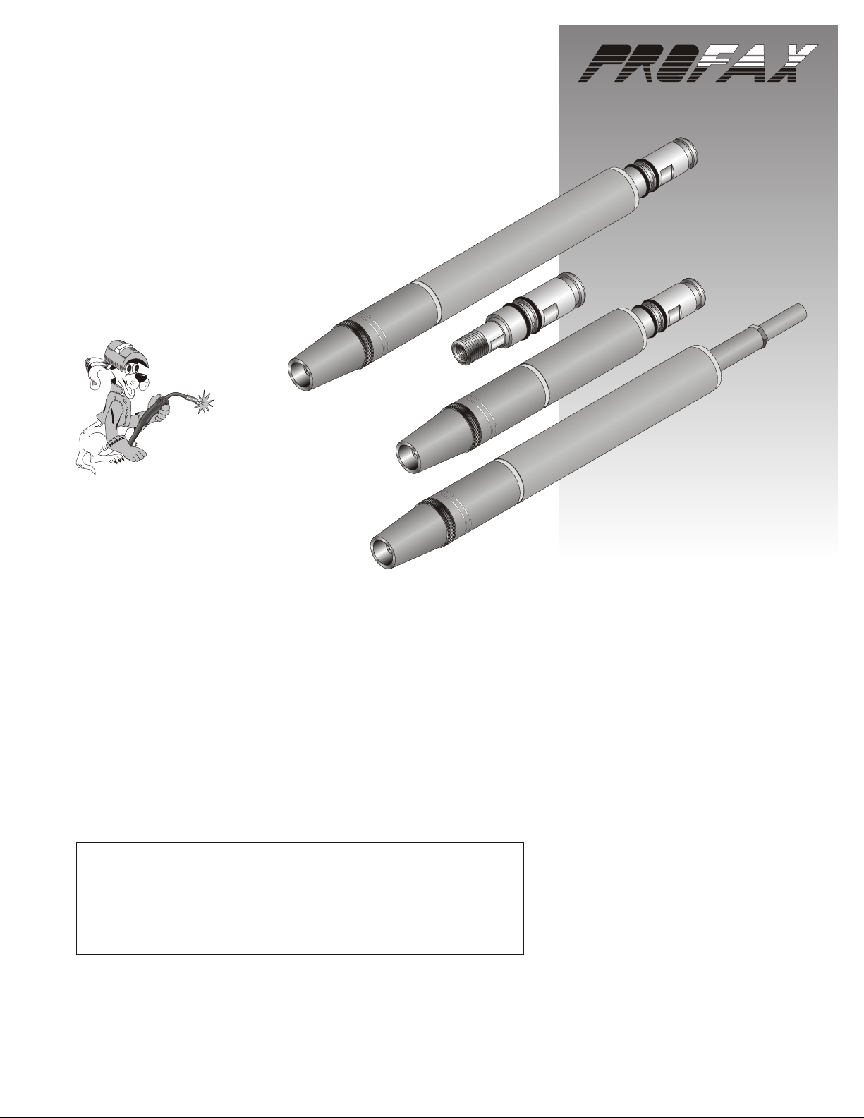
Description
The 500 Amp AMT Mig Gun is available in 2’, 4’, 6’, 8’, 10’, 12’, 15’, 20’
and 25’ cable assemblies and is capable of running .035 to 7/64” wire
sizes. Please consult, the parts list to order the proper components for
your wire size.
Special length guns available on request.
IMPORTANT - PROTECT YOURSELF AND OTHERS!
Remember safety depends on you. Do not install, operate or repair
this equipment without reading and understanding the installation
instructions along with the Warnings and Safeguards for Welding
and Cutting Operation form WSWC594.
500 AMP AMT MIG GUN500 AMP AMT MIG GUN
500 AMP AMT MIG GUN500 AMP AMT MIG GUN
00015OG080807
Made in U.S.A.
Page 2
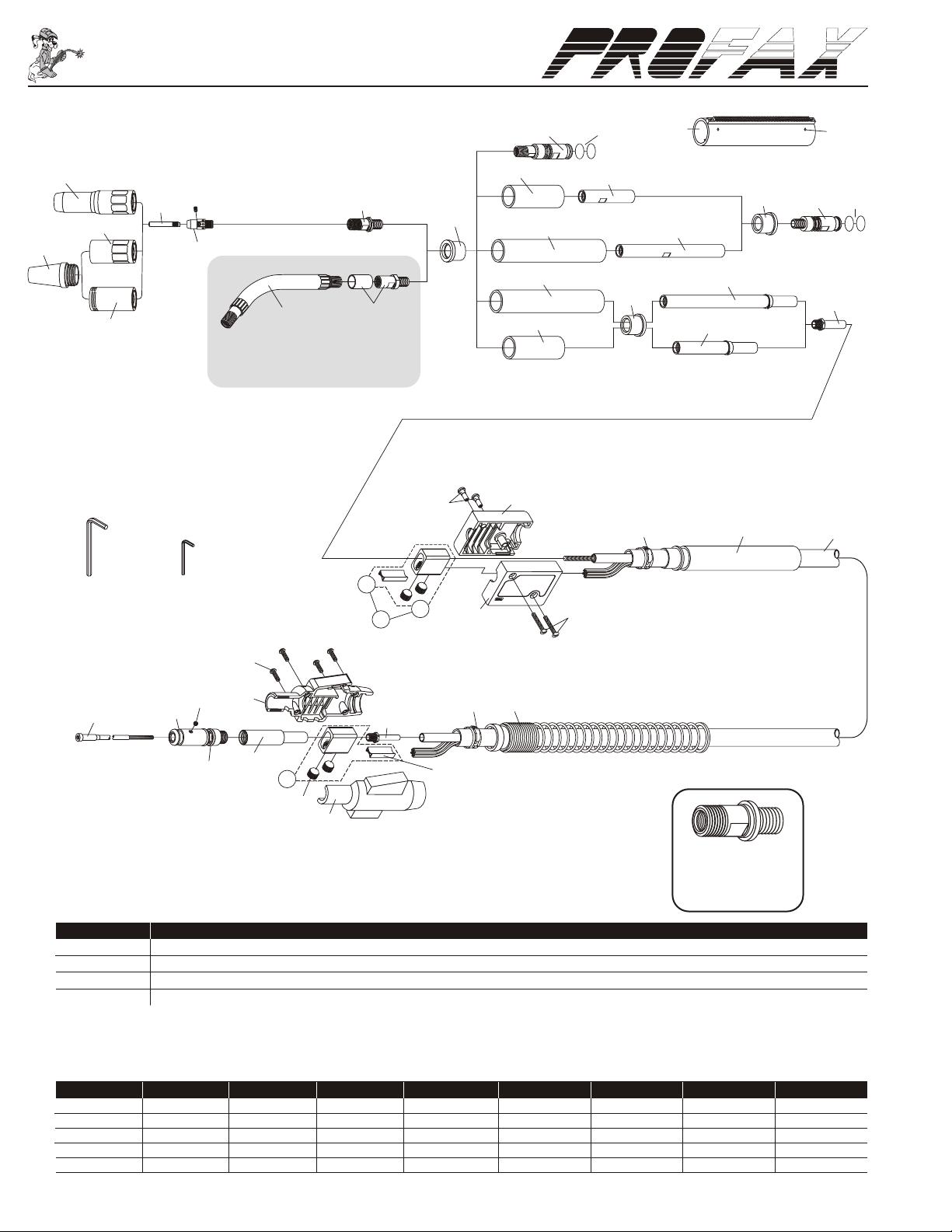
Parts BreakdownParts Breakdown
® ®
Parts Breakdown
8
1a
4
3
2a
1
2
5
6b
6
7
6a
9
11
11
9
14
10
32
7
12
15
7
16
4
14
13
17
When using optional front end on
500 amp AMT you must use
400 amp consumables
21
22
23
26
27
AL-300-25
7/32” hex wrench
31
44-25
5/64” hex wrench
4
30
14
24
25
29
20
19
18
19
20
17
18
25
500 Amp AMT Mig Guns
PART NO. DESCRIPTION
65AMT-175 500 amp body w/plug - for use with 12” units.
65MAMT-175 500 amp miniature body
65SAMT-175 500 amp short body w/plug - for use with 8-3/4” units.
65AMTN 500 Amp Body w/Nipple - for use with cable hose type units.
22
28
23
21
55AMT-B
Allows Bernard style front
end parts to be used on the
500 amp torch.
®
Complete 500 Amp AMT Mig Gun Packages
2’ 4’ 6’ 8’ 10’ 12’ 15’ 20’ 25’
AMT500-3545-2 AMT500-3545-4 AMT500-3545-6 AMT500-3545-8 AMT500-3545-10 AMT500-3545-12 AMT500-3545-15 AMT500-3545-20 AMT500-3545-25
AMT500-116-2 AMT500-116-4 AMT500-116-6 AMT500-116-8 AMT500-116-10 AMT500-116-12 AMT500-116-15 AMT500-116-20 AMT500-116-25
AMT500-564-2 AMT500-564-4 AMT500-564-6 AMT500-564-8 AMT500-564-10 AMT500-564-12 AMT500-564-15 AMT500-564-20 AMT500-564-25
AMT500-332-2 AMT500-332-4 AMT500-332-6 AMT500-332-8 AMT500-332-10 AMT500-332-12 AMT500-332-15 --- --AMT500-764-2 AMT500-764-4 AMT500-764-6 AMT500-764-8 AMT500-764-10 AMT500-764-12 AMT500-764-15 --- ---
Page 3

Parts ListParts List
Parts List
NO. PART NO. DESCRIPTION
1. PX25CT-50 Nozzle 1/2”, coarse thread
PX25CT-62 Nozzle 5/8”, coarse thread (std.)
PX25CT-75 Nozzle 3/4”, coarse thread
1a. PX25I-62 Nozzle 5/8”, self insulated
PX25I-75 Nozzle 3/4”, self insulated
2. PX35CT Insulator, use w/coarse thread nozzle (std.)
2a. PX35CT-HT Insulator, high temp
3. PX15H35 Contact tip .035
PX15H45 Contact tip .045
PX15H52 Contact tip .052
PX15H116 Contact tip 1/16”
PX15H564 Contact tip 5/64”
PX15H332 Contact tip 3/32”
PX15H764 Contact tip 7/64”
PX15AH364 Contact tip 3/64” (for aluminum)
PX15AH116 Contact tip 1/16” (for aluminum)
PX15HFC35 Contact tip .035
PX15HFC45 Contact tip .045
PX15HFC52 Contact tip .052
PX15HFC116 Contact tip 1/16”
PX15HFC564 Contact tip 5/64”
PX15HFC332 Contact tip 3/32”
PX15HFC764 Contact tip 7/64”
PX15AHFC364 Contact tip 3/64” (for aluminum)
PX15AHFC116 Contact tip 1/16” (for aluminum)
4. PX44C Set screw for gas diffuser and conduit
5. PX55 Gas diffuser
PX55H Gas diffuser
PX55SW Gas diffuser
6. PX55AMT 500 amp head
6a. PX54TAMT Optional head for gooseneck
6b. PX505-22 Gooseneck 22°
PX505-45 Gooseneck 45°
PX505-60 Gooseneck 60°
7. PX45IN Insulator (2 req'd)
8. PX65MAMT-175 Miniature body
9. PX45OTS Outer tube short
10. PX45ITPS Short internal tube (plug)
11. PX450TL Outer tube long
12. PX45ITPL Long internal tube (plug)
13. PX175AMT 500 amp plug
14. PX225 O-ring
NO. PART NO. DESCRIPTION
15. PX65ITNL Internal tube long (w/18-480 snap ring)
16. PX65ITNS Internal tube short (w/18-480 snap ring)
17. PX65N Nipple
18. PX114 Separator
19. PXA-532-24 9/16-18 ball point screws
20. PX104 Cable connector block assembly
21. PX125FM Binder screws for connector block
22. PX185 Connector block w/binder screws
23. PX134-16 Clamp - connector block (2 req’d)
24. PXR185-SC Screws for housing (4)
25. PXR185-H Housing
26. PX235-12 Hose support 12”
27. PX500-10 10’ replacement cable assembly
PX500-12 12’ replacement cable assembly
PX500-15 15’ replacement cable assembly
PX500-20 20’ replacement cable assembly
PX500-25 25’ replacement cable assembly
PX500K Replacement cable assembly, bulk
28. PXR185-S Spring
29. PXR175-UA Standard connector plug
PXR175-UAG Connector plug with gas hole w/65N
30. PXR175-T Connector, standard
PXR175-L Connector, Lincoln
PXR175-M Connector, Miller (w/175M-N nipple)
31. PX45-3545-1 1’ wire conduit assy. used w/.035-.045 dia. wire
PX45-116-1 1’ wire conduit assy. used w/1/16” dia. wire
PX45-564-1 1’ wire conduit assy. used w/5/64” dia. wire
PX45H-332-1 1’ wire conduit assy. used w/3/32” dia. wire
PX45H-764-1 1’ wire conduit assy. used w/7/64” dia. wire
PX45-3545-15 15’ wire conduit assy. used w/.035-.045 dia. wire
PX45-116-15 15’ wire conduit assy. used w/1/16” dia. wire
PX45-564-15 15’ wire conduit assy. used w/5/64” dia. wire
PX45H-332-15 15’ wire conduit assy. used w/3/32” dia. wire
PX45H-764-15 15’ wire conduit assy. used w/7/64” dia. wire
PX45-3545-25 25’ wire conduit assy. used w/.035-.045 dia. wire
PX45-116-25 25’ wire conduit assy. used w/1/16” dia. wire
PX45-564-25 25’ wire conduit assy. used w/5/64” dia. wire
32. PX24PAMT Barrel w/rack 24 pitch (Optional)
PX32PAMT Barrel w/rack 32 pitch (Optional)
®
®
Page 4

®
Electric shock can cause INJURY or DEATH.
IMPORTANT- Disconnect all electrical power to the welding power source and wire feeder before
attempting installation of this unit.
Your PROFAX 500 Amp AMT Mig-Gun comes standard with a Tweco style rear connector. Adapter Kits for most domestic
style feeders as well as a Euro-Quick connector for European style feeders are also available. Please note that non GMA wire
feeders will require a gas solenoid valve.
®
INSTALLATION
1.) Make sure that the gun is equipped with the proper contact tip and conduit for the type and size of wire to be used before
installation.
2.) Make sure that the adapter, the feeder outgoing guide, and the drive rolls are correct for the type and size of wire to be
used.
3.) Lay the PROFAX AMT Mig Gun out in a straight line.
4.) Push the brass connector end of the gun cable into the brass adapter on the outgoing side of feeder wire drive until it is
fully seated. Secure the cable with the set or hand screw in the adapter.
5.) Remove the nozzle and contact tip from the AMT Mig Gun.
6.) Relieve tension and disengage drive rolls. Feed wire by hand through drive rolls, outgoing guide and adapter plug until
wire is at least one too two feet inside of PROFAX AMT Mig Gun.
7.) Reset drive rolls and apply proper tension. Keep gun in a straight position. Continue to feed wire through the gun by
using the inch button on the feeder or gun trigger.
8.) Install the nozzle and contact tip back onto the AMT Mig Gun.
9.) When you activate gun trigger, the contact tip and welding wire protruding from tip are electrically “HOT”. Set the power
source to the proper settings for wire size and welding application to be used. Make sure the shielding gas supply is
adjusted to the proper flow rate. Gun is now ready for operation.
GUIDELINES TO AVOID WIRE FEEDING PROBLEMS AND
TO KEEP YOUR MIG GUN OPERATING SMOOTHLY
1.) Use only good quality welding wires that are clean and rust free.
2.) Keep the cable assembly as straight as possible, and do not kink or pull cable around sharp corners or allow carts or
trucks to run over the cable assembly.
3.) Make sure the contact tip is tightly screwed into the gas diffuser at all times. Frequently clean the contact tip and nozzle.
The use of a good anti-spatter compound will increase tip and nozzle life and will make spatter removal easier. If the
contact tip becomes deformed, arced or worn at the end, replace it immediately.
4.)On a regular basis, check all gun, cable and gas hose connections. Make sure they are clean and tight.
BY FOLLOWING THESE SIMPLE GUIDELINES YOU WILL
EXTEND THE LIFE OF YOUR PROFAX AMT MIG GUN.
 Loading...