

Made in U.S.A.
®
P.O. Box 898 • Pearland, TX 77588-0898
3
NO.PROFAX DESCRIPTION
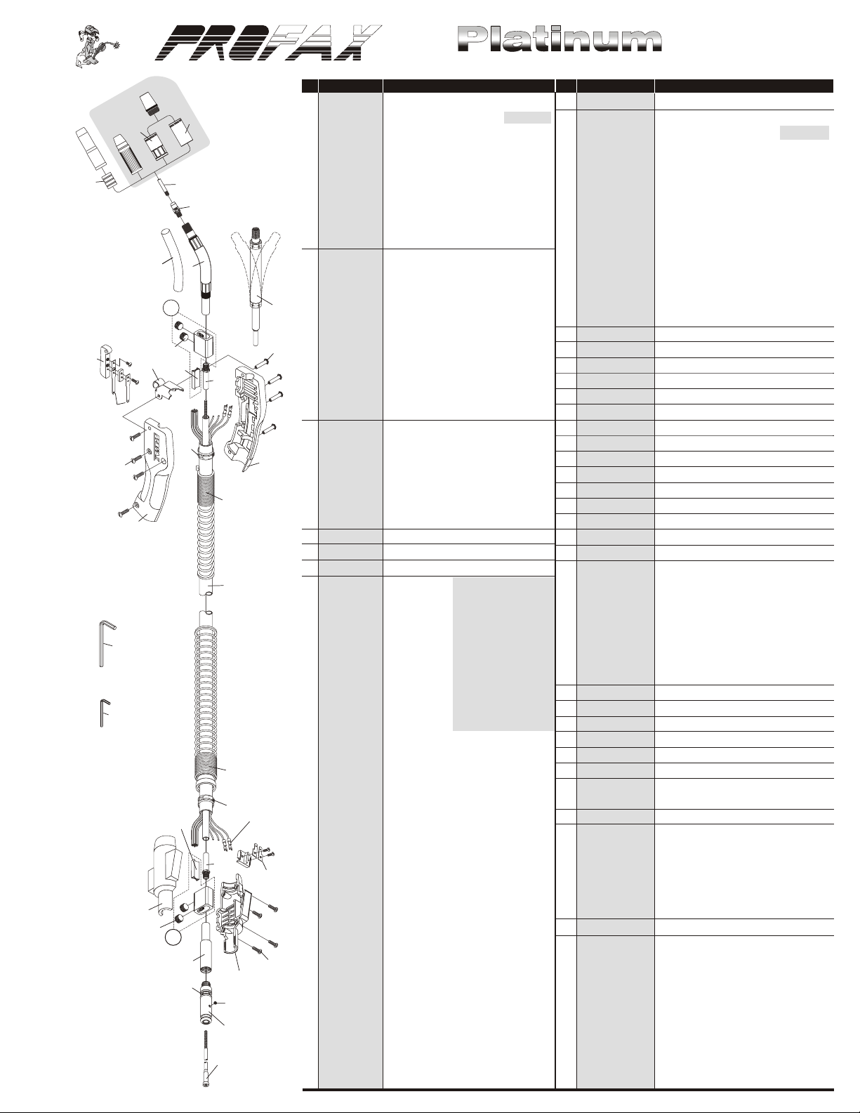
1. PX24A50 Nozzle 1/2”, adj. use w/34A
Optional
1
5a
2
5
PX24A62 Nozzle 5/8”, adj. use w/34A (standard)
PX24A75 Nozzle 3/4”, adj. use w/34A
PX24A50SS Nozzle 1/2”, short stop, adj. use w/34A
PX24A62SS Nozzle 5/8”, short stop, adj. use w/34A
4
6
8
7
PX24A75SS Nozzle 3/4”, short stop, adj. use w/34A
PX24AH50 Nozzle 1/2”, HD, adj. use w/34A
PX24AH62 Nozzle 5/8”, HD, adj. use w/34A
PX24AH75 Nozzle 3/4”, HD, adj. use w/34A
PX24AT37SS Nozzle 3/8”, short stop, tap. use w/34A
9a
9
2. PX23-37 Nozzle 3/8”, self insulated
PX23-50 Nozzle 1/2”, self insulated
PX23-62 Nozzle 5/8”, self insulated
14
11
PX23-75 Nozzle 3/4”, self insulated
PX23-37F Nozzle 3/8”, self insulated, flush
PX23-50F Nozzle 1/2”, self insulated, flush
22
21
13
15
12
10
24a
17
PX23-62F Nozzle 5/8”, self insulated, flush
PX23-75F Nozzle 3/4”, self insulated, flush
PX23H50 Nozzle 1/2”, HD, self insulated
PX23H62 Nozzle 5/8”, HD, self insulated
PX23T37 Nozzle 3/8”, self insulated, tapered
3. PX24CT50F Nozzle 1/2”, use w/34CT (flush tip)
18
17
16
16
23
PX24CT62F Nozzle 5/8”, use w/34CT (flush tip)
PX24CT75F Nozzle 3/4”, use w/34CT (flush tip)
PX24CT37S Nozzle 3/8”, use w/34CT (recessed tip)
PX24CT50S Nozzle 1/2”, use w/34CT (recessed tip)
PX24CT62S Nozzle 5/8”, use w/34CT (recessed tip)
PX24CT75S Nozzle 3/4”, use w/34CT (recessed tip)
4. PX34A Insulator
5. PX34CT Insulator w/coarse thread nozzle
5a. PX34CT-HT Insulator, high temp
24
6. PX14-23 Contact tip .023
PX14-30 Contact tip .030
PX14-35 Contact tip .035
PX14-40 Contact tip .040
19
PX14-45 Contact tip .045
PX14-52 Contact tip .052
PX14-116 Contact tip 1/16”
PX14-564 Contact tip 5/64”
20
PX14A364 Contact tip 3/64”(for aluminum)
PX14A116 Contact tip 1/16”(for aluminum)
PX14H35 Contact tip .035, HD
PX14H40 Contact tip .040, HD
25
PX14H45 Contact tip .045, HD
PX14H52 Contact tip .052, HD
26
12
24a
PX14H116 Contact tip 1/16”, HD
PX14H564 Contact tip 5/64”, HD
PX14AH364 Contact tip 3/64”, HD (for aluminum)
PX14AH116 Contact tip 1/16”, HD (for aluminum)
10
27
PX14HT35 Contact tip .035
PX14HT40 Contact tip .040
PX14HT45 Contact tip .045
28
13
14
30
32a
32
29
28
31
PX14HT52 Contact tip .052
PX14HT116 Contact tip 1/16”
PX14HT564 Contact tip 5/64”
PX14T23 Tapered contact tip .023
PX14T30 Tapered contact tip .030
PX14T35 Tapered contact tip .035
PX14T40 Tapered contact tip .040
PX14T45 Tapered contact tip .045
PX14T52 Tapered contact tip .052
PX14T116 Tapered contact tip 1/16”
33
7. PX54A Gas diffuser
PX54C Gas diffuser copper
Compact 400 Amp Mig Gun Parts List
NO. PROFAX DESCRIPTION
8. PX44C Set screw for gas diffuser/conduit
9. PX64A30J Jacketed conductor tube 30°
PX64A45J Jacketed conductor tube 45° (standard)
PX64A45-9J Jacketed conductor tube 45° - 9 inch
PX64A60J Jacketed conductor tube 60°
PX64A60-9J Jacketed conductor tube 60° - 9 inch
PX64A60-3RJ Jacketed conductor tube 60°, 3”radius
PX64A80J Jacketed conductor tube 80°
PX64A180J Jacketed conductor tube 180°
PX64A30 Conductor tube 30°
PX64A45 Conductor tube 45°
PX64A60 Conductor tube 60°
PX64A60-3R Conductor tube 60°, 3” radius
PX64A80 Conductor tube 80°
PX64A180 Conductor tube 180°
9a. 74A Replacement neoprene insulator
10. PX64N Nipple
11. PXTF-4 Flexible barrel
12. PX114 Separator
13. PXA-532-24 9/16”-18 ball point screws
14. PX104 Cable connector block assembly
15. PX154HD Hanger
16. PX84C Compact handle w/binder screws
17. PX122FM Binder screws for handle
18. PX134-14 Clamp - handle
19. PXAL-300-25 7/32” hex wrench
20. PX44-25 5/64” hex wrench
21. PX92C Switch contacts w/screws
22. PX92 Trigger switch assembly
23. PX144-6S Spring strain relief for handle
24. PX400-10 10’ replacement cable assembly
PX400-12 12’ replacement cable assembly
PX400-15 15’ replacement cable assembly
PX400-20 20’ replacement cable assembly
Standard
series
contact tip
PX400-25 25’ replacement cable assembly
PX400K Cable, bulk (per foot)
PX400CK Cloth wrapped cable, bulk (per foot)
for guns longer than 15’
24a PX244 Terminal
25. PXR185-S spring
26. PX134-14 Clamp - connector block
27. PX194 Connector tab assembly
28. PXR185-H Housing
29. PXR185-SC Screws for housing (4)
30. PXR174-UA Standard connector plug w/64n
PXR174-UAG Connector plug w/gas hole w/64N
31. PX44C Set screw for conduit 8-32
32. PXR174-C Connector, Century
PXR174-E Connector, Esab
PXR174-H Connector, Hobart
PXR174-L Connector, Lincoln
PXR174-M Connector, Miller
®
®
®
®
®
PXR174-T Connector, standard
32a PX224 O-ring
33. PX44-3545-15 15’ wire conduit assembly .035-.045
PX44-116-15 15’ wire conduit assembly .052-1/16”
PX44-564-15 15’ wire conduit assembly 5/64”
PX44-3545-25 25’ wire conduit assembly .035-.045
PX44-116-25 25’ wire conduit assembly .052-1/16”
PX44-564-25 25’ wire conduit assembly 5/64”
PX44N-3545-15 15’ nylon lined conduit assembly
(aluminum) .035-.047
PX44N-116-15 15’ nylon lined conduit assembly
(aluminum) 1/16”
Compact 400 Amp Mig Gun Packages
PART NO. DESCRIPTION
400-3545-10 10’ in length, .035-.045 wire size (use w/44-3545-15 liner)
400-052-10 10’ in length, .052 wire size (use w/44-116-15 liner)
400-116-10 10’ in length, 1/16” wire size (use w/44-116-15 liner)
400-564-10 10’ in length, 5/64” wire size (use w/44-564-15 liner)
400-3545-12 12’ in length, .035-.045 wire size (use w/44-3545-15 liner)
400-052-12 12’ in length, .052 wire size (use w/44-116-15 liner)
400-116-12 12’ in length, 1/16” wire size (use w/44-116-15 liner)
400-564-12 12’ in length, 5/64” wire size (use w/44-564-15 liner)
400-3545-15 15’ in length, .035-.045 wire size (use w/44-3545-15 liner)
400-052-15 15’ in length, .052 wire size (use w/44-116-15 liner)
PART NO. DESCRIPTION
400-116-15 15’ in length, 1/16” wire size (use w/44-116-15 liner)
400-564-15 15’ in length, 5/64” wire size (use w/44-564-15 liner)
400-3545-20 20’ in length, .035-.045 wire size (use w/44-3545-25 liner)
400-052-20 20’ in length, .052 wire size (use w/44-116-25 liner)
400-116-20 20’ in length, 1/16” wire size (use w/44-116-25 liner)
400-564-20 20’ in length, 5/64” wire size (use w/44-564-25 liner)
400-3545-25 25’ in length, .035-.045 wire size (use w/44-3545-25 liner)
400-052-25 25’ in length, .052 wire size (use w/44-116-25 liner)
400-116-25 25’ in length, 1/16” wire size (use w/44-116-25 liner)
400-564-25 25’ in length, 5/64” wire size (use w/44-564-25 liner)
Electric shock can cause INJURY or DEATH.
IMPORTANT- Be sure that the power source and feeder are in the off position. Make sure input power to the power source is
disconnected at the electrical breaker box before attempting installation of this unit.
PROFAX standard rear connection for use with the TAK-1, TLAK-1, PROFAX Pro II, Pro IV, Hobart series 2000,2200,2210,2400,2410, Heavy
Duty, Model 17, Hefty, Mijit 17, Portafeed 17, Portawire 17, Por tafeed 1000, Ultrafeed 1000, Lincoln Wirematic 250 & 255, LN 10, DH10, &
SST10, Powcon PD-1, PD-IE & PDVS-1, Thermal Dynamics TA-3, TAF-2, TAF-4 & Viking 250.
®®
*Please specify feeder brand so correct trigger plug will be included.
All references to original manufacturer’s equipment numbers, and/or trade names or trademarks, are for identification and
convenience only. The trademarks and trade names are the property of their respective owners.
®
®
INSTALLATION
1.) Lay the PROFAX Mig-Gun out in a straight line.
2.) Push the brass connector end of the gun cable into the brass adapter on the outgoing side of feeder wire drive until it is fully seated.
Secure the cable with the set or hand screw in the adapter.
3.) Install the control plug assembly into mating socket on gun cable and into trigger circuit receptacle on feeder.
4.) Relieve tension and disengage drive rolls. Feed wire by hand through drive rolls, outgoing guide and adapter plug until wire is at least one
to two feet inside of PROFAX Mig-Gun.
5.) Reset drive rolls and apply proper tension. Keep gun in a straight position. Continue to feed wire through gun and contact tip by using
inch button on feeder or gun trigger.
6.) When you activate gun trigger, the contact tip and welding wire protruding from tip are electrically “HOT”. Set the power source to the
proper settings for wire size and welding application to be used. Make sure the shielding gas supply is adjusted to the proper flow rate.
Gun is now ready for operation.
GUIDELINES TO AVOID WIRE FEEDING PROBLEMS AND
TO KEEP YOUR MIG-GUN OPERATING SMOOTHLY
1.) Use only clean rust free good quality welding wire.
2.) Keep cable assembly as straight as possible, do not kink or pull cable over sharp corners or allow cart wheels or trucks to run over
cables.
3.) Make sure contact tip is tightly screwed into the gas diffuser at all times, also make sure that the gas diffuser is tightly screwed into the
conductor tube. Retighten the diffuser and tip periodically. Frequently clean contact tip and nozzles. The use of a good anti-spatter
compound will increase tip and nozzle life and make spatter removal easier. If contact tip becomes deformed or arced at the end, replace
immediately.
4.) Maintain and make certain all gun connections are secured and electrical connections are tight. New guns should have all electrical
connections retighten after several days of initial use. Check all gas hose connections on a regular basis to make sure no leakage or loss
of flow occurs.
By following these simple guidelines you will
extend the life of your new PROFAX Mig-Gun.
Keep all mechanical and electrical connections tight.
00107OG072210
 Loading...