


-

The information provided in this documentation contains general descriptions and/or
technical characteristics of the performance of the products contained herein. This
documentation is not intended as a substitute for and is not to be used for
determining suitability or reliability of these products for specific user applications. It
is the duty of any such user or integrator to perform the appropriate and complete
risk analysis, evaluation and testing of the products with respect to the relevant
specific application or use thereof. Neither Pro-face nor any of its affili a te s or
subsidiaries shall be responsible or liable for misuse of the information contained
herein. If you have any suggestions for improvements or amendments or have found
errors in this publication, please notify us.
No part of this document may be reproduced in any form or by any means, electronic
or mechanical, including photocopying, without express written permission of Proface.
All pertinent state, regional, and local safety regulations must be observed when
installing and using this product. For reasons of safety and to help ensure
compliance with documented system data, only the manufacturer should perform
repairs to components.
When devices are used for applications with technical safety requirements, the
relevant instructions must be followed.
Failure to use Pro-face software or approved software with our hardware products
may result in injury, harm, or improper operating results.
Failure to observe this information can result in injury or equipment damage.
Copyright © 2013.9 Digital Electronics Corporation . All Rig hts Reserved.
2

PS-4600 Series User Manual
Table of Contents
Safety Information . . . . . . . . . . . . . . . . . . . . . . . . . . . . . . 5
About the Book. . . . . . . . . . . . . . . . . . . . . . . . . . . . . . . . . 7
Part I General Overview. . . . . . . . . . . . . . . . . . . . . . . . . . . . 13
Chapter 1 Important Information . . . . . . . . . . . . . . . . . . . . . . . . . . . 15
Federal Communications Commission Radio Frequency Interference
Statement - For U.S.A. . . . . . . . . . . . . . . . . . . . . . . . . . . . . . . . . . . . . . . . 16
Qualified Personnel. . . . . . . . . . . . . . . . . . . . . . . . . . . . . . . . . . . . . . . . . . 17
Certifications and Standards. . . . . . . . . . . . . . . . . . . . . . . . . . . . . . . . . . . 18
European (CE) Compliance . . . . . . . . . . . . . . . . . . . . . . . . . . . . . . . . . . . 20
Hazardous Location Installations - For USA and Canada. . . . . . . . . . . . . 21
Chapter 2 Physical Overview . . . . . . . . . . . . . . . . . . . . . . . . . . . . . . 27
Package Contents. . . . . . . . . . . . . . . . . . . . . . . . . . . . . . . . . . . . . . . . . . . 28
Industrial Personal Computer - Description. . . . . . . . . . . . . . . . . . . . . . . . 30
Industrial Personal Computer LED and Push Button Description . . . . . . . 33
Chapter 3 Characteristics . . . . . . . . . . . . . . . . . . . . . . . . . . . . . . . . . 35
Industrial Personal Computer Characteristics. . . . . . . . . . . . . . . . . . . . . . 36
Industrial Personal Computer Interface Characteristics . . . . . . . . . . . . . . 41
Environmental Characteristics. . . . . . . . . . . . . . . . . . . . . . . . . . . . . . . . . . 42
Chapter 4 Dimensions/Assembly . . . . . . . . . . . . . . . . . . . . . . . . . . . 43
Industrial Personal Computer Dimensions . . . . . . . . . . . . . . . . . . . . . . . . 44
Installation Requirements . . . . . . . . . . . . . . . . . . . . . . . . . . . . . . . . . . . . . 48
Industrial Personal Computer Installation . . . . . . . . . . . . . . . . . . . . . . . . . 52
Part II Implementation. . . . . . . . . . . . . . . . . . . . . . . . . . . . . . 55
Chapter 5 Getting Started . . . . . . . . . . . . . . . . . . . . . . . . . . . . . . . . . 57
First Power-up. . . . . . . . . . . . . . . . . . . . . . . . . . . . . . . . . . . . . . . . . . . . . . 57
Chapter 6 Industrial Personal Computer Connections. . . . . . . . . . 59
Grounding . . . . . . . . . . . . . . . . . . . . . . . . . . . . . . . . . . . . . . . . . . . . . . . . . 60
Connecting the DC Power Cord . . . . . . . . . . . . . . . . . . . . . . . . . . . . . . . . 64
Connecting the AC Power Cord . . . . . . . . . . . . . . . . . . . . . . . . . . . . . . . . 66
Industrial Personal Computer Interface Connections . . . . . . . . . . . . . . . . 68
Chapter 7 Configuration of the BIOS . . . . . . . . . . . . . . . . . . . . . . . . 73
BIOS Options . . . . . . . . . . . . . . . . . . . . . . . . . . . . . . . . . . . . . . . . . . . . . . 74
Main Menu . . . . . . . . . . . . . . . . . . . . . . . . . . . . . . . . . . . . . . . . . . . . . . . . 77
Advanced Menu - PCI and PCIe configuration - USB Configuration . . . . 80
Boot Menu . . . . . . . . . . . . . . . . . . . . . . . . . . . . . . . . . . . . . . . . . . . . . . . . 98
Security Menu . . . . . . . . . . . . . . . . . . . . . . . . . . . . . . . . . . . . . . . . . . . . . 101
Exit Menu . . . . . . . . . . . . . . . . . . . . . . . . . . . . . . . . . . . . . . . . . . . . . . . . . 103
Chapter 8 Hardware Modifications. . . . . . . . . . . . . . . . . . . . . . . . . . 105
8.1 Before Modifications . . . . . . . . . . . . . . . . . . . . . . . . . . . . . . . . . . . . . . . . . 106
Before Modifications . . . . . . . . . . . . . . . . . . . . . . . . . . . . . . . . . . . . . . . . . 106
3

Table of Contents
8.2 AC Power Supply Unit, Battery Unit and UPS. . . . . . . . . . . . . . . . . . . . . 108
AC Power Supply Unit Description and Installation. . . . . . . . . . . . . . . . . 109
Uninterruptible Power Supply (UPS) Battery Unit Description
and Installation . . . . . . . . . . . . . . . . . . . . . . . . . . . . . . . . . . . . . . . . . . . . . . . .
8.3 Interface Modules . . . . . . . . . . . . . . . . . . . . . . . . . . . . . . . . . . . . . . . . . . 124
Interface Module Installation . . . . . . . . . . . . . . . . . . . . . . . . . . . . . . . . . . 125
COM Expansion Board Description. . . . . . . . . . . . . . . . . . . . . . . . . . . . . 130
UPS Interface Module Description. . . . . . . . . . . . . . . . . . . . . . . . . . . . . . 133
8.4 Slot Expansion. . . . . . . . . . . . . . . . . . . . . . . . . . . . . . . . . . . . . . . . . . . . . 134
Slot Expansion Installation. . . . . . . . . . . . . . . . . . . . . . . . . . . . . . . . . . . . 135
Slide-in Slot Installation . . . . . . . . . . . . . . . . . . . . . . . . . . . . . . . . . . . . . . 139
PCI/PCIe Card Installation. . . . . . . . . . . . . . . . . . . . . . . . . . . . . . . . . . . . 145
8.5 Slide-in Disk Drive and Fan Kit . . . . . . . . . . . . . . . . . . . . . . . . . . . . . . . . 152
Slide-in Disk Drive Description and Installation . . . . . . . . . . . . . . . . . . . . 153
Fan Kit Installation and Removing . . . . . . . . . . . . . . . . . . . . . . . . . . . . . . 157
8.6 Main Memory Cards and CFast Cards . . . . . . . . . . . . . . . . . . . . . . . . . . 159
CFast Card Installation and Removal . . . . . . . . . . . . . . . . . . . . . . . . . . . 160
Main Memory Card Description and Installation . . . . . . . . . . . . . . . . . . . 162
8.7 RAID . . . . . . . . . . . . . . . . . . . . . . . . . . . . . . . . . . . . . . . . . . . . . . . . . . . . 166
RAID . . . . . . . . . . . . . . . . . . . . . . . . . . . . . . . . . . . . . . . . . . . . . . . . . . . . 166
Part III Installation . . . . . . . . . . . . . . . . . . . . . . . . . . . . . . . . . 171
Chapter 9 System Monitor . . . . . . . . . . . . . . . . . . . . . . . . . . . . . . . . . 173
System Monitor Interface. . . . . . . . . . . . . . . . . . . . . . . . . . . . . . . . . . . . . 174
System Monitor Setting . . . . . . . . . . . . . . . . . . . . . . . . . . . . . . . . . . . . . . 180
Chapter 10 Maintenance. . . . . . . . . . . . . . . . . . . . . . . . . . . . . . . . . . . . 183
Reinstallation Procedure . . . . . . . . . . . . . . . . . . . . . . . . . . . . . . . . . . . . . 184
Regular Cleaning and Maintenance. . . . . . . . . . . . . . . . . . . . . . . . . . . . . 185
Appendices . . . . . . . . . . . . . . . . . . . . . . . . . . . . . . . . . . . . . . . . . . . 191
Appendix A Accessories . . . . . . . . . . . . . . . . . . . . . . . . . . . . . . . . . . . . 193
Accessories for the Industrial Personal Computer. . . . . . . . . . . . . . . . . . 193
115
4

§
Safety Information
Important Information
NOTICE
Read these instructions carefully, and look at the equipment to become familiar with
the device before trying to install, operate, or maintain it. The following special
messages may appear throughout this documentation or on the equipment to warn
of potential hazards or to call attention to information that clarifies or simplifies a
procedure.
PS-4600 Series User Manual
5

Safety Information
PLEASE NOTE
Electrical equipment should be installed, operated, serviced, and maintained only by
qualified personnel. No responsibility is assumed by Pro-face for any consequences
arising out of the use of this material.
A qualified person is one who has skills and knowledge related to the construction
and operation of electrical equipment and its installation, and has received safety
training to recognize and avoid the hazards involved.
6

PS-4600 Series User Manual
About the Book
At a Glance
Document Scope
This manual describes the configuration and usage of PS-4600 Series (Hereafter
referred to as the “Industrial Personal Computer”).
The configuration number format is as follows:
Character Number Prefix (1-4) 5 6 7 8 9 10 11 12 13 14 15 16 17 18
Part Number Exam-
ple
iPC Family Standard Model P
Product Generation Reserved *
Display 12" - XGA 6
Expansion Slots 0 slot 0
CPU Type Celeron 827E D
Power Supply*1 AC A
RAM (Configuration
available depending
on OS)
*1 When using UPS Battery Unit, only one COM Expansion Board can be installed in the interface module slot 2.
PFXP P161DD23G21N00
Rear Mount Model F
1 slot = 1 PCI 1
1 slot = 1 PCIe C
2 slots = 1 PCI+1 PCIe 2
2 slots = 2 PCI A
Core i3 E
DC with interface for UPS Battery Unit B
DC D
AC with interface for UPS Battery Unit U
1GB 1
2GB 2
3GB=1GB+2GB 3
4GB=4GB 5
6GB=2GB+4GB 6
8GB 8
12 GB = 8 GB + 4 GB C
16 GB = 8 GB + 8 GB G
7

About the Book
Character Number Prefix (1-4) 5 6 7 8 9 10 11 12 13 14 15 16 17 18
Part Number Exam-
ple
Operating System None 0
Storage Device None N
Slide-in Slot
NOTE: for 1 and 2
slots Industrial
Personal Computer.
Options None 0
Software Bundle None N
Reserved None *
Reserved None *
PFXP P 1 6 1 D D 2 3 G 2 1 N 0 0
Windows Embedded Standard 2009 MUI 1
Windows XP Pro Japanese 2
Windows XP Pro MUI 3
Windows Embedded Standard 7 Premium MUI (32-bit) 4
Windows 7 Ultimate MUI (32-bit) 5
Windows 7 Ultimate MUI (64-bit) 6
CFast 4 GB G
CFast 8 GB H
CFast 16 GB J
Primary CFast 4 GB + Secondary CFast 4 GB
(for Windows Embedded Standard 2009 MUI)
Primary CFast 8 GB + Secondary CFast 4 GB
(for Windows Embedded Standard 7 Premium MUI [32-bit])
HDD 500 GB P
SSD 60 GB T
SSD 128 GB U
None 0
DVD multi drive 1
HDD 500 GB 2
SSD 60 GB 6
COM Expansion Board 4
COM Expansion Board + COM Expansion Board W
WinGP G
L
M
NOTE: All instructions applicable to the enclosed product and all safety precautions must be observed.
8

Validity Note
PS-4600 Series User Manual
This documentation is valid for PS-4600 Series.
The technical characteristics of the devices described in this manual also appear
online. To access this information online , ple ase go to our site
http://www.proface.com/otasuke/
The characteristics that are presented in this manual should be the same as those
characteristics that appear online. In line with our policy of constant improvement,
we may revise content over time to improve clarity and accuracy. If you see a
difference between the manual and online information, use the online information as
your reference.
Registered Trademarks
The company names and product names used in this manual are the trade names,
trademarks (including registered trademarks), and service marks of their respective
companies. This product omits individual descriptions of each of these rights.
Trademark / Tradename Right Holder
Microsoft, Windows Microsoft, U. S.
Pro-face Digital Electronics Corporation
(in Japan and other countries)
Intel Intel Corporation
Related Documents
Global Code
The following terms differ from the abovementioned trade names and trademarks.
Term used in this manual Formal Trademark or Tradename
Windows Embedded Standard 2009 Microsoft® Windows® Embedded Standard Runtime
Windows Embedded Standard 7 Windows® Embedded Standard 7 Runtime
(WS7P)(ESD)
Windows XP Pro Microsoft® Windows® XP Professional for Embedded
Systems (1-2 CPU) ESD
Windows 7 Windows® 7 Ultimate for Embedded Systems x32/x64
(1-2 CPU) (ESD)
Celeron 827E Intel® Celeron® Processor 827E
Core i3
Title of Documentation
PS-4600 Series User Manual (this manual)
Intel® Core
TM
i3 Processor 3217UE
You can download these technical publications and other technical information from
our website “Otasuke Pro!” at http://www.pro-face.com/otasuke/.
A global code is assigned to every Pro-face product as a universal reference. For
more information on product models and their matching global codes, please refer
to the following URL.
URL: http://www.pro-face.com/product/globalcode.html
9

About the Book
Product Related Information
Some Industrial Personal Computers are certified for use in Class I, Division 2
hazardous locations as defined in ANSI/ISA 12.12.01 or CSA C22.2 N213.
Observe the following:
HAZARD OF ELECTRIC SHOCK, EXPLOSION OR ARC FLASH
Remove all power from the device before removing any covers or elements of
the system, and prior to installing or removing any accessories, hardware, or
cables.
Unplug the power cable from both the Industrial Personal Computer and the
power supply.
Always use a properly rated voltage sensing device to confirm power is off.
Replace and secure all covers or elements of the system before applying power
to the unit.
Use only the specified voltage when operating the Industrial Personal
Computer. The AC unit is designed to use 100...240 Vac input. The DC unit is
designed to use 24 Vdc. Always check whether your device is AC or DC
powered before applying power.
Failure to follow these instructions will result in death or serious injury.
DANGER
WARNING
LOSS OF CONTROL
The designer of any control scheme must consider the potential failure modes
of control paths and, for certain critical control functions, provide a means to
achieve a safe state during and after a path failure. Examples of critical control
functions are emergency stop and overtravel stop.
Separate or redundant control paths must be provided for critical control
functions.
System control paths may include communication links. Consideration must be
given to the implications of unanticipated transmission delays or failures of the
(1)
link.
Each implementation of an Industrial Personal Computer must be individually
and thoroughly tested for proper operation before being placed into service.
Failure to follow these instructions can result in death, serious injury, or
equipment damage.
(1)
For additional information, refer to NEMA ICS 1.1 (latest edition), “Safety
Guidelines for the Application, Installation, and Maintenance of Solid State Control”
and to NEMA ICS 7.1 (latest edition), “Safety Standards for Construction and Guide
for Selection, Installation and Operation of Adjustable-Speed Drive Systems” or
other applicable standards in your location.
NOTE: The Industrial Personal Computer is a highly configurable device and is not
based on a real-time operating system. Changes to the software and settings of the
following must be considered new implementatio ns as discussed in the previ ous
warning messages. Examples of such changes include:
System BIOS
System Monitor
10

PS-4600 Series User Manual
Operating system
Installed hardware
Installed software
WARNING
UNINTENDED EQUIPMENT OPERATION
Use only Pro-face software with the devices described in this manual.
Failure to follow these instructions can result in death, serious injury, or
equipment damage.
11

About the Book
12

Magelis Industrial Personal Computer12”
General Overview
EIO0000001596 04/2013
Subject of this Part
What Is in This Part?
PS-4600 Series User Manual
General Overview
I
This part provides an overview of the Industrial Personal Computer products.
This part contains the following chapters:
Chapter Chapter Name Page
1 Important Information 15
2 Physical Overview 27
3 Characteristics 35
4 Dimensions/Assembly 43
13

General Overview
14

Magelis Industrial Personal Computer12”
Important Information
EIO0000001596 04/2013
Important Information
General
This chapter describes specific aspects related to the operation of the Industrial
Personal Computer.
What Is in This Chapter?
This chapter contains the following topics:
Federal Communications Commission Radio Frequency Interference Statement - For U.S.A.
Qualified Personnel 17
Certifications and Standards 18
European (CE) Compliance 20
Hazardous Location Installations - For USA and Canada 21
PS-4600 Series User Manual
1
Topic Page
16
15

Important Information
Federal Communications Commission Radio Frequency Interference Statement
- For U.S.A.
FCC Radio Interference Information
This equipment has been tested and found to comply with the Federal
Communications Commission (FCC) limits for a Class A digital device, pursuant to
Part 15 of the FCC Rules. These limits are designed to provide reasonable
protection against harmful interference in a commercial, industrial or business
environment. This equipment generates, uses, and can radiate radio frequency
energy and, if not installed and used in accordance with the instructions, may cause
or be subject to interference with radio communications. To minimize the possibility
of electromagnetic interference in your application, observe the following two rules:
Install and operate the Industrial Personal Computer in such a manner that it
does not radiate sufficient electromagnetic energy to cause interference in
nearby devices.
Install and test the Industrial Personal Computer to ensure that the
electromagnetic energy generated by nearby devices does not interfere with the
Industrial Personal Computer’s operation.
WARNING
ELECTROMAGNETIC / INTERFERENCE
Electromagnetic radiation may disrupt the Industrial Personal Computer’s
operations, leading to unintended equipment operation. If electromagnetic
interference is detected:
Increase the distance between the Industrial Personal Computer and the
interfering equipment.
Reorient the Industrial Personal Computer and the interfering equipment.
Reroute power and communication lines to the Industrial Personal Computer
and the interfering equipment.
Connect the Industrial Personal Computer and the interfering equipment to
different power supplies.
Always use shielded cables when connecting the Industrial Personal Computer
to a peripheral device or another computer.
Failure to follow these instructions can result in death, serious injury, or
equipment damage.
16

Qualified Personnel
General
Only qualified personnel can install, operate, and maintain the product. A qualified
person is one who has skills and knowledge related to the construction, operation,
and installation of electrical equipment, and has received safety training to
recognize and avoid the hazards involved. Refer to the most current release of
NFPA 70E®, Standard for Electrical Safety in the Workplace, for electrical safety
training requirements or other applicable standards in your location. Examples of
qualified personnel may include:
at the application design level, engineerin g department personnel who are
at the equipment implementation level, personnel who are familiar with the
at the operation level, personnel who are experienced in the use and control of
for preventive or corrective maintenance, personnel trained and qualified in
PS-4600 Series User Manual
familiar with automation safety concepts (for example, a design engineer)
installation, connection and commissioning of automation equipment (for
example, an installation assembly or cabling engineer or a commissioning
technician)
automation and computing equipment (for example, an operator)
regulating or repairing automated and computing devices (for example, an
operating technician or after-sales service technician.)
17

Important Information
Certifications and Standards
Agency Certifications
Pro-face submitted this product for independent testing and qualification by thirdparty agencies. These agencies have certified this product as meeting the following
standards:
Underwriters Laboratories Inc., UL 508 and CSA C22.2 N142, Industrial Control
Equipment
Underwriters Laboratories Inc., ANSI/ISA 12.12.01 and CSA C22.2 N213,
Electrical Equipment for Use in Class I, Division 2 Hazardous (Classified)
Locations
GOST-R certification
For information on certifications and standards, such as certified models and
certificates, see the following or product markings.
http://www.pro-face.com/worldwide.html
Compliance Standards
Pro-face tested this product for compliance with the following compulsory standards:
United States:
Federal Communications Commission, FCC Part 15 Class A
Europe: CE
Directive 2006/95/EC (Low Voltage)
Directive 2004/108/EC (EMC)
Programmable Controllers: EN 61131-2 (Ed 3)
EMI: EN 61000-6-4
EMS: EN 61000-6-2
Australia:
Standard EN61000-6-4 (RCM)
Qualification Standards
Pro-face voluntarily tested this product to additional standards. The additional tests
performed, and the standards under which the tests were conducted, are specifically
identified in Environmental Characteristics (see page 42).
18

Hazardous Substances
This product is compliant with:
WEEE, Directive 2012/19/EU
RoHS, Directive 2011/65/EU
RoHS China, Standard SJ/T 11363-2006
REACH regulation EC 1907/2006
End of Life (Battery)
The product contains electronic boards. It must be disposed of in specific treatment
channels. The product contains cells and/or storage batteries which must be
collected and processed separately, when they have run out and at the end of
product life.
Refer to the section Maintenance (see page 183) to extract cells and batteries from
the product. These batteries do not contain a weight percentage of heavy metals
over the threshold notified by European Directive 2006/66/EC.
KC Marking
PS-4600 Series User Manual
19

Important Information
European (CE) Compliance
CE Compliance Note
The products described in this manual comply with the European Directives
concerning Electromagnetic Compatibility and Low Voltage (CE marking) when
used as specified in the relevant documentation, in applications for which they are
specifically intended, and in connection with approved third-party products.
20

Hazardous Location Installations - For USA and Canada
General
The Industrial Personal Computer has been designed with the intention of meeting
the requirements of Class I, Division 2 hazardous location applications. Division 2
locations are those locations where ignitable concentrations of flammable
substances are normally confined, prevented by ventilation, or presen t in an
adjacent Class I, Division 1 location, but where an abnormal situation might result in
intermittent exposure to such ignitable concentrations.
While the Industrial Personal Computer is a non-incendive device under
ANSI/ISA 12.12.01 and CSA C22.2 N213, it is not designed for, and should never
be used within a Division 1 (normally hazardous) location.
This equipment is suitable for use in Class I, Division 2, Groups A, B, C, and D
hazardous locations or in non-hazardous locations. Before installing or using your
Industrial Personal Computer, confirm that the ANSI/ISA 12.12.01 or
CSA C22.2 N213 certification appears on the product labeli ng
NOTE: Some Industrial Personal Computer devices are not yet rated as suitable for
use in hazardous locations. Always use your product in conformance with the
product labeling and this manual.
DANGER
PS-4600 Series User Manual
POTENTIAL FOR EXPLOSION
Do not use your Industrial Personal Computer in hazardous environments or
locations other than Class I, Division 2, Groups A, B, C, and D.
Always confirm that your Industrial Personal Computer is suitable for use in
hazardous locations by checking that the ANSI/ISA 12.12.01 or
CSA C22.2 N213 certification appears on the product labeling.
Do not install any Pro-face or OEM components, equipment, or accessories
unless these have also been qualified as suitable for use in Class I, Division 2,
Groups A, B, C, and D locations.
In addition, confirm that any PCI controller cards have an adequate temperature
code (T-code), and are suitable for a surrounding air temperature range of
0to50C (32to122F).
Do not attempt to install, operate, modify, maintain, service, or otherwise alter
the Industrial Personal Computer except as permitted in this manual.
Unpermitted actions may impair the unit’s suitability for Class I, Division 2
operation.
Failure to follow these instructions will result in death or serious injury.
21

Important Information
DANGER
POTENTIAL FOR EXPLOSION
Always confirm the ANSI/ISA 12.12.01 and CSA C22.2 N213 hazardous
location rating of your device before installing or using it in a hazardous location.
To power on or power off a Industrial Personal Computer installed in a Class I,
Division 2 hazardous location, you must either:
Use a switch located outside the hazardous environment, or
Use a switch certified for Class I, Division 1 operation inside the hazardous
area.
Do not connect or disconnect equipment unless power has been switched off or
the area is known to be non-hazardous. This applies to all connections including
power, ground, serial, parallel, network and rear USB connections.
Never use unshielded / ungrounded cables in hazardous locations.
When enclosed, keep enclosure doors and openings closed at all times to avoid
the accumulation of foreign matter inside the workstation.
Use only non-incendive front USB configurations (see page 69).
Failure to follow these instructions will result in death or serious injury.
DANGER
HAZARD OF ELECTRIC SHOCK, EXPLOSION OR ARC FLASH
Remove all power from the device before removing any covers or elements of
the system, and prior to installing or removing any accessories, hardware, or
cables.
Unplug the power cable from both the Industrial Personal Computer and the
power supply.
Always use a properly rated voltage sensing device to confirm power is off.
Replace and secure all covers or elements of the system before applying power
to the unit.
Use only the specified voltage when operating the Industrial Personal
Computer. The AC unit is designed to use 100...240 Vac input. The DC unit is
designed to use 24 Vdc. Always check whether your device is AC or DC
powered before applying power.
Failure to follow these instructions will result in death or serious injury.
Ensure that the product is properly rated for the location. If the intended location
does not presently have a Class, Division and Group rating, then users should
consult the appropriate authorities having jurisdiction in order to determine the
correct rating for that hazardous location.
In accordance with Federal, State/Provincial, and Local regulations, all hazardous
location installations should be inspected prior to use by the appropriate authority
having jurisdiction. Only technically qualified personnel should install, service, and
inspect these systems.
22

Power Switch
PS-4600 Series User Manual
DANGER
HAZARD OF ELECTRIC SHOCK, EXPLOSION OR ARC FLASH
Remove all power from the device before removing any covers or elements of
the system, and prior to installing or removing any accessories, hardware, or
cables.
Unplug the power cable from both the Industrial Personal Computer and the
power supply.
Always use a properly rated voltage sensing device to confirm power is off.
Replace and secure all covers or elements of the system before applying power
to the unit.
Use only the specified voltage when operating the Industrial Personal
Computer. The AC unit is designed to use 100...240 Vac input. The DC unit is
designed to use 24 Vdc. Always check whether your device is AC or DC
powered before applying power.
Failure to follow these instructions will result in death or serious injury.
The amount of input power required by systems with a Industrial Personal Computer
classifies the power switch as an incendive device because the voltage and current
across the make/break component are capable of generating a spark.
If using an ordinary power switch, hazardous location regulations require the power
switch be located in an area specified as non-hazardous.
However, limits in cable length between the workstation and the power switch may
apply. Otherwise the switch must be compliant with Class I, Division 1 requirements
(intrinsically safe). These switches are built in a manner that prevents the possibility
of a spark when contact is made or broken.
Use suitable UL listed and/or CSA Certified Class I, Division 1 switches in hazardous
locations. These switches are available from a wide number of source s. It is the
responsibility to ensure you select a power switch that conforms to the hazardous
location rating for the installation.
23

Important Information
Cable Connections
DANGER
POTENTIAL FOR EXPLOSION
Always confirm the ANSI/ISA 12.12.01 and CSA C22.2 N213 hazardous
location rating of your device before installing or using it in a hazardous location.
To power on or power off a Industrial Personal Computer installed in a Class I,
Division 2 hazardous location, you must either:
Use a switch located outside the hazardous environment, or
Use a switch certified for Class I, Division 1 operation inside the hazardous
area.
Do not connect or disconnect equipment unless power has been switched off or
the area is known to be non-hazardous. This applies to all connections including
power, ground, serial, parallel, network and rear USB connections.
Never use unshielded / ungrounded cables in hazardous locations.
When enclosed, keep enclosure doors and openings closed at all times to avoid
the accumulation of foreign matter inside the workstation.
Use only non-incendive front USB configurations (see page 69).
Failure to follow these instructions will result in death or serious injury.
Division 2 hazardous location regulations require that all cable connections be
provided with adequate strain relief and positive interlock. Use only non-incendive
USB devices as USB connections do not provide adequate strain relief to allow the
use of Industrial Personal Computer USB connections (see page 69). Never
connect or disconnect a cable while power is applied at either end of the cable. All
communication cables should include a chassis ground shield. This shield should
include both copper braid and aluminum foil. The D-sub style connector housing
must be a metal conductive type (for example, molded zinc) and the ground shield
braid must be terminated directly to the connector housing. Do not use a shield drain
wire.
The outer diameter of the cable must be suited to the inner diameter of the cable
connector strain relief so that a reliable degree of strain relief is maintained. Always
secure the D-Sub connectors to the workstation-mating connectors via the two
screws located on both sides.
24

Operation and Maintenance
The systems have been designed for compliance with relevant spark ignition tests
for front USB connection only.
POTENTIAL FOR EXPLOSION
In addition to the other instructions in this manual, observe the following rules when
installing the Industrial Personal Computer in a hazardous location:
Wire the equipment in accordance with the National Electrical Code article
501.10 (B) for Class I, Division 2 hazardo us locations.
Install the Industrial Personal Computer in an enclosure suitable for the specific
application. IP65 enclosures are recommended even when not required by
regulations.
The device must be installed in an end-use enclosure, which may only be
opened by the use of a tool (tool secured enclosure).
Failure to follow these instructions will result in death or serious injury.
NOTE: IP65 is not part of UL certificat io n .
PS-4600 Series User Manual
DANGER
25

Important Information
26

Magelis Industrial Personal Computer12”
Physical Overview
EIO0000001596 04/2013
Physical Overview
Subject of this Chapter
This chapter provides a physical overview of the Industrial Personal Computer.
What Is in This Chapter?
This chapter contains the following topics:
Package Contents 28
Industrial Personal Computer - Description 30
Industrial Personal Computer LED and Push Button Description 33
PS-4600 Series User Manual
2
Topic Page
27

Physical Overview
Package Contents
Items
The following items are included in the package of the Industrial Personal Computer.
Before using the Industrial Personal Computer, confirm that all items listed here are
present:
Industrial Personal Computer: 1
Installation Fasteners:
10 per set only for Standard Models.
Restore DVD-ROM containing the software
required to reinstall the Operating System
Documents Warning/Caution Information (1)
The MS Windows EULA
PS4000 Series Installation Guide (1)
Connector Cover
28

PS-4600 Series User Manual
DC Terminal Block
(For the DC Industrial Personal Computer
only)
AC Terminal Block
(For the AC Industrial Personal Computer
only)
This Industrial Personal Computer has been carefully packed, with special attention
to quality. However, should you find anything damaged or missing, contact your
local distributor immediately.
29

Physical Overview
Industrial Personal Computer - Description
Introduction
The following Industrial Personal Computer 12" - description shows the port
interfaces, the expansion slots, the Slide-in Disk, the CFast slot and the power
supplies.
During operation, surface temperatures of the heat sink may reach more than 70 C
(158 F).
RISK OF BURNS
Do not touch the surface of the heat sink during operation.
Failure to follow these instructions can result in death, serious injury, or
equipment damage.
Front View
WARNING
30
1 Display
2 Touch panel
3 Front USB (USB5 max. 500 mA) with cover (Except for Rear Mount Model)
NOTE:
The front USB is a diagnostic interface for service and maintenance.
Front USB cover must be tighten with 0.55 ±0.05Nm (4.87 ±0.44 lb-in) to comply
with degree of protection NEMA 4x Indoor and IP65.
CAUTION
OVERTORQUE AND LOOSE HARDWARE
Do not exert more than 0.55 ±0.05Nm (4.87 ±0.44 lb-in) of torque when
tightening the screw of the Front USB cover. Tightening the screw with
excessive force can damage the screw and cover.
When installing or removing screws, ensure that they do not fall inside the
Industrial Personal Computer chassis.
Failure to follow these instructions can result in injury or equipment damage.

Rear View
+
–
2
3
1
PS-4600 Series User Manual
NOTICE
UNINTENDED EQUIPMENT OPERATION
Do not use the front USB while the machine is in operation.
Always keep the cover in place during normal operation.
Failure to follow these instructions can result in equipment damage.
Left View
1 Battery
2 Interface modules cover
3 RAM HDD cover
1 Status LEDs
2 Power/Reset buttons
3 Slide-in Disk
4 Main memory cards
5 CFast slot
31

Physical Overview
Top View
Bottom View
1 Location for optional fan necessary for the operation with HDD storage device into Slide-
in Disk
1 USB2
2 USB1
3 ETH1 (10/100/1000 MBit)
4 ETH2 (10/100/1000 MBit)
5 USB3
6 USB4
7 DVI-I
8 MIC, Line IN, Line out
9 COM2
10 COM1
11 Add-on interface module slot 2 (IF2)
12 Add-on interface module slot 1 (IF1)
13 Ground connection
14 DC power connector
Bottom View for Industrial Personal Computer with AC Power Supply and Slot Expansion
1 Power switch
2 AC power connector (with AC terminal block)
3 Slot expansion and Slide-in Slot
4 PCI / PCIe slot half size
32

PS-4600 Series User Manual
Industrial Personal Computer LED and Push Button Description
LED Description
The following figure shows the LEDs and push button on the Industrial Personal
Computer:
1 [Power] LED
2 [HDD] LED
3 [Link] LED
4 [RUN] LED
5 [POWER] button
6 [RESET] button
NOTE: Modifying products to install an HDD into a Slide-in Disk when it was not
installed from factory, requires to change the unit firmware settings for proper
behavior of the fan (that are required when running with HDD into a Slide-in Disk) Please contact Pro-face support if you want to proceed such modification.
33

Physical Overview
Status LED
The following table describes the meaning of the status LEDs on the Industrial
Personal Computer:
LED Color State Meaning
[Power] Green On Supply voltage is OK.
Flashing The device has booted, the battery status is low. The data buffering is
provided for approximately 500 hours from the point when the battery capacity is recognized as insufficient.
Red On The system is in standby mode (S5: Soft-off mode or S4: hibernate mode
- suspend-to-disk).
Flashing Not supported
Green/Red 3 flash green
1flash red
1 flash green
3flash red
Flashing
green/red
Flashing
red/green
[HDD] Orange On Indicates IDE drive access (CFast, HDD, CD and so on).
[Link] Orange On/Flashing Not supported
[Run] Green On/Flashing Not supported
Faulty or incomplete BIOS, controller or I/O FPGA update, battery status
OK, power supply OK.
Faulty or incomplete BIOS, controller or I/O FPGA update, battery status
OK, standby mode (S5: Soft-off mode or S4: hibernate mode - suspendto-disk).
Faulty or incomplete BIOS, controller or I/O FPGA update, battery status
BAD, power supply OK.
Faulty or incomplete BIOS, controller or I/O FPGA update, battery status
BAD, standby mode (S5: Soft-off mode or S4: hibernate mode - suspendto-disk).
Power Button
Reset button
Press the power button with a pointed object (for example, paper clip or tip of a pen).
The power button acts like the On/Off switch on a normal desktop PC with a
controller power supply:
Press and release: switches on the Industrial Personal Computer or shuts down
the operating system and switches off the Industrial Personal Computer.
Press and hold: controller power supply switches off without shutting down the
Industrial Personal Computer (data could be lost!).
Pressing the power button does not reset the processor.
Press the reset button with a pointed object (for example, paper clip or tip of a pen).
Pushing the reset button triggers a hardware and PCI reset. The Industrial Personal
Computer restarts cold.
Pressing the reset button does not reset the processor.
34

Magelis Industrial Personal Computer12”
Characteristics
EIO0000001596 04/2013
Characteristics
Subject of this Chapter
This chapter lists the product characteristics.
What Is in This Chapter?
This chapter contains the following topics:
Industrial Personal Computer Characteristics 36
Industrial Personal Computer Interface Characteristics 41
Environmental Characteristics 42
PS-4600 Series User Manual
3
Topic Page
35

Characteristics
Industrial Personal Computer Characteristics
Characteristics of Celeron 827E Pre-installed Models
The characteristics of the Celeron 827E Pre-installed models are shown below:
Element Characteristics
0slot 1slot 2slots
Expansion Slots – 1 = 1 PCI or PCIe 2 = 1 PCI + 1 PCIe
or
2=2PCI
Slide-in Slot None 1 slide-in equipped with one
of the following:
DVD-RW
or HDD, SSD, CFast
(with Slide-in Disk
Adapter unit) through
Slide-in Slot Adapter unit
Intel® Chipset and Pro-
Celeron M 827E 1.40 GHz + 1.5 MB (do not support RAID option)
cessor
Cooling Method Passive heat sink for the operation without HDD storage device into Slide-in Disk. Option-
al fan kit necessary for the operation with HDD storage device into Slide-in Disk.
SDRAM 2 x DDR3 25.6 GB/s - 16 GB max
Graphics Controller Intel® HD Graphics 3000
Video Mem-
Up to 1 GB (reserved from main memory)
ory
Color depth 32-bit (maximum)
RGB Reso-
350 MHz RAMDAC, up to 2048 x 1537 @75 Hz (QXGA)
lution
DVI Resolu-
Up to 1920 x 1200 (WUXGA)
tion
Slide-in Disk 1 slot equipped
HDD, SSD or CFast with Slide-in Disk Adapter unit
NOTE: Modifying products to install an HDD into a Slide-in Disk when it was not installed
from factory, requires to change the unit firmware settings for proper behavior of the fan
(that are required when running with HDD into a Slide-in Disk) - Please contact Pro-face
support if you want to proceed such modification.
CFast TYPE-I 1SLOT
Reset Button Yes
Buzzer Buzzer support is depending on OS (for example, no support for Windows® 7 Ultimate
(32-bit) and Windows® 7 Ultimate (64-bit).
Industrial
Personal
Computer
Weight
Standard
Model
Rear Mount
Model
4.0 kg (8.81 lb) 4.1 kg (9.03 lb) 4.2 kg (9.26 lb)
3.9 kg (8.59 lb) 4.0 kg (8.81 lb) 4.1 kg (9.03 lb)
1 slide-in equipped with one
of the following:
DVD-RW
or HDD, SSD, CFast
(with Slide-in Disk
Adapter unit) through
Slide-in Slot Adapter unit
36

PS-4600 Series User Manual
Characteristics of Core i3 Pre-installed Models
The characteristics of the Core i3 Pre-installed models are shown below:
Element Characteristics
0 slot 1 slot 2 slots
Expansion Slots – 1 = 1 PCI or PCIe 2 = 1 PCI + 1 PCIe
or
2=2PCI
Slide-in Slot None 1 slide-in equipped with one
of the following:
DVD-RW
or HDD, SSD, CFast
(with Slide-in Disk
Adapter unit) through
Slide-in Slot Adapter unit
Intel® Chipset and Pro-
Intel® Core™ i3-3217UE 1.60 GHz + 3 MB (support RAID option)
cessor
Cooling Method Passive heat sink for the operation without HDD storage device into Slide-in Disk. Optional
fan kit necessary for the operation with HDD storage device into Slide-in Disk.
SDRAM 2 x DDR3 25.6 GB/s - 16 GB max
Graphics Controller Intel® HD Graphics 4000
Video Mem-
Up to1 GB (reserved from main memory)
ory
Color depth 32-bit (maximum)
RGB Reso-
350 MHz RAMDAC, up to 2048 x 1537 @75 Hz (QXGA)
lution
DVI Resolu-
Up to 1920 x 1200 (WUXGA)
tion
Slide-in Disk 1 slot equipped
HDD, SSD or CFast with Slide-in Disk Adapter unit
NOTE: Modifying products to install an HDD into a Slide-in Disk when it was not installed
from factory, requires to change the unit firmware settings for proper behavior of the fan
(that are required when running with HDD into a Slide-in Disk) - Please contact Pro-face
support if you want to proceed such modification.
CFast TYPE-I 1SLOT
Reset Button Yes
Buzzer Buzzer support is depending on OS (for example, no support for Windows® 7 Ultimate
(32-bit) and Windows® 7 Ultimate (64-bit).
Industrial
Personal
Computer
Weight
Standard
Model
Rear Mount
Model
4.0 kg (8.81 lb) 4.1 k g (9.03 lb) 4.2 kg (9.26 lb)
3.9 kg (8.59 lb) 4.0 k g (8.81 lb) 4.1 kg (9.03 lb)
1 slide-in equipped with one
of the following:
DVD-RW
or HDD, SSD, CFast
(with Slide-in Disk
Adapter unit) through
Slide-in Slot Adapter unit
37

Characteristics
Display Characteristics
Element 12" Screen Size
Graphics XGA TFT active matrix (1024 x 768 pixels)
Number of Colors 16 million
Brightness Control Step less adjustment
Touch Sensitive
Screen
Backlight LED - Life span > 50,000 h @ 25 C (77 F)
DC Power Supply
Element Characteristics
Rated Voltage 24 Vdc ±25 %
Power Consumption 130 W (max.)
Inrush Current Typical 7 A, max. 60 A < 300 s
Battery Backup Optional UPS
AC Power Supply
Analog resistive film, resolution 4,096 x 4,096
Element Characteristics
Rated Voltage 100...240 Vac
Frequency 50/60 Hz
Rated Current 0.6...2 A (max.)
Inrush Current < 20 A (Cold restart, 100 % load, 100 Vac).
Battery Backup Optional UPS
38

Operating Systems
PS-4600 Series User Manual
Element Characteristics
*1
Operating System
HDD or SSD: Windows® XP Professional SP3/Windows® 7 Ultimate
*2
: Windows® Embedded Standard 2009/Windows® Embed-
CFast
ded Standard 7 Premium
*1 For details on languages supported by pre-installed operating systems, read "The List of
OS Pre-installed Languages for Multi-language" (see page 40).
*2 For Windows® Embedded Standard 2009, CFast of 4 GB or more is required. For Win-
dows® Embedded Standard 7 Premium, CFast of 8 GB or more is required.
39

Characteristics
The List of OS Pre-installed Languages for Multi-la nguage
Windows® XP
Professional
Arabic *1
Bulgarian —*1
Chinese(Simplified) *1
Chinese(Traditional) *1
Croatian —*1
Czech *1
Danish *1
Dutch *1
English
Estonian —*1
Finnish *1
French
German
Greek *1
Hebrew *1
Hungarian *1
Italian
Japanese
Korean *1
Latvian ——*1
Lithuanian —*1
Norwegian *1
Polish *1
Portuguese *1
Portuguese(Brazil) *1
Romanian —*1
Russian *1
Serbian Latin — —*1
Slovak —*1
Slovenian —*1
Spanish
Swedish
Thai —*1
Turkish *1
Ukrainian — —*1
Windows® 7
Ultimate
Windows®
Embedded
Standard 2009
Windows®
Embedded
Standard 7
*1
40
*1 The languages can be downloaded from Pro-face Home Page "Otasuke Pro!".
http://www.pro-face.com/otasuke/

Industrial Personal Computer Interface Characteristics
Serial Interface
Element Characteristics
Amount 2
Type RS-232C, modem-capable, not electrically isolated
UART 16550-compatible, 16-byte FIFO
Transfer Rate Maximum 115 kbps
Connection D-Sub 9 pin, plug (see page 68)
USB Interface
Element Characteristics
Type USB5
Type USB1...4 USB 2.0
Amount
Transfer Rate Low speed (1.5 Mbit/s), full speed (12 Mbit/s), high speed
Connection Type A (see page 68)
Current load
*1
USB 2.0
(USB 3.0: for Core i3 models with Windows
Embedded Standard 7)
5 (4 bottom side and 1 front side
(480 Mbit/s), to super speed (5 GBit/s)
Maximum 500 mA per connection for USB5
Maximum 1 A per connection for USB1, USB2, USB3 and USB4
PS-4600 Series User Manual
®
7 or Windows®
*1
)
*1
Ethernet Interface
*1 USB5 is Front USB equipped on the models except for Rear Mount Model.
Element Characteristics
Amount 2 x RJ45
Speed 10/100/1000 Mbit/s
NOTE: The serial, USB and Ethernet interfaces on this product have internal port
numbers that may differ from their physical port numbers, such as “ETH1” or
“USB1”, used for identification in this manual. As the internal port number assigned
to the interface differs between operating systems, please check the interface in
your environment.
Ethernet Interface Example)Physical port number on this product : ETH1 ETH2
Internal port number (Windows® 7) : LAN1 LAN2
Internal port number (Windows® XP) : LAN2 LAN1
41

Characteristics
Environmental Characteristics
Characteristics
The environmental characteristics of the Industrial Personal Computer are as
follows:
Characteristics Value Standards
Degree of Protection IP65, Type 4X (Indoor use only)
when the front USB cover is closed on
the models except for Rear Mount Model
Pollution Degree For use in Pollution Degree 2 environment EN/IEC 61131-2
Surrounding air temperature dur-
ing operation
0...50 C (32...122 F)
when using HDD running with a fan kit,
SSD or CFast
0...45 C (32...113 F):
when using Gigabit Ethernet
5...45 C (41...113 F):
when using DVD multi drive
Storage temperature – 20...60 C (– 4...140 F) IEC 60068-2-2 tests Bb,
Operating altitude 2000 m (6560 ft) max EN/IEC 61131-2
Vibration EN/IEC 60068-2-6 Fc
Operation (continuous) for prod-
ucts with SSD or CFast card storage device.
Operation (continuous) for products with HDD storage device.
Operation (occasional) for products with SSD or CFast card storage device.
Operation (occasional) for products with HDD storage device.
Shock Resistance (in operation)
Surrounding air humidity during
operation
2...9 Hz: 1.5 mm
9...200 Hz: 4.9 m/s
2
5...8.4 Hz: 1.75 mm
8.4...150 Hz: 4.9 m/s
5...100 Hz: 1.225 m/s
2
2
2...9 Hz: 3 mm
9...200 Hz: 9.8 m/s
2
5...8.4 Hz: 3.5 mm
8.4...150 Hz: 9.8 m/s
5...100 Hz: 2.450 m/s
2
147 m/s
for a duration of 11 ms
2
2
10...85 % RH (Wet bulb temperature: 29 C
(84.2 F) max. - no condensation)
Storage humidity 10...85 % RH (Wet bulb temperature: 29 C
(84.2 F) max. - no condensation)
Electromagnetic Compatibility
(EMC)
Immunity to High Frequency Interference EN/IEC 61131-2, IEC 61000-4-x
Electromagnetic Emissions Class A EN61000-6-4
IEC60529, UL50E
EN/IEC 61131-2, UL 508
IEC 60068-2-14 tests Na
IEC 60068-2-27 Ea test
EN/IEC 60068-2-78 Cab
EN/IEC 60068-2-30 Db
NOTE: IEC 61131-2 and IP65 are not part of UL certification.
42

Magelis Industrial Personal Computer12”
Dimensions/Assembly
EIO0000001596 04/2013
Dimensions/Assembly
Subject of this Chapter
This chapter describes Industrial Personal Computer dimensions and installation
panels.
What Is in This Chapter?
This chapter contains the following topics:
Industrial Personal Computer Dimensions 44
Installation Requirements 48
Industrial Personal Computer Installation 52
PS-4600 Series User Manual
4
Topic Page
43

Dimensions/Assembly
DVD-RW
247
9.72
3,5
0.14
313
12.32
33
1.30
239
9.41
185,5
7.30
26,75
1.05
R3
59,5
2.34
A
9
0.35
14,5
0.57
225
8.86
300
11.81
6,5
0.26
mm
in.
1...9 mm
0.04...0.35 in
Industrial Personal Computer Dimensions
Standard Models - 0, 1 and 2 Slot Dimensions
The figure shows the dimensions of the Industrial Personal Computer 12":
44
NOTE: Measurement “A” depends on the number of slot PCI/PCIe cards
(see page 45).

Values
PS-4600 Series User Manual
The table provides the “A” measurement value:
Industrial Personal Computer 12” “A” Value
0 slot Industrial Personal Computer 59.5 mm (2.342 in.)
1 slot Industrial Personal Computer 114.2 mm (4.496 in.)
2 slots Industrial Personal Computer 134.5 mm (5.295 in.)
The table shows the general tolerance for the Industrial Personal Computer
dimensions:
Nominal Measurement General Tolerance acc. DIN ISO 2768 Medi-
um
up to 6mm (up to 0.236 in.) ±0.1 mm (±0.004 in.)
over 6 to 30 mm (over 0.236 to 1.181 in.) ±0.2 mm (±0.0078 in.)
over 30 to 120 mm (over 1.18 to 4.724 in.) ±0.3 mm (±0.012 in.)
over 120 to 400 mm (over 4.724 to
15.747 in.)
±0.5 mm (±0.02 in.)
45

Dimensions/Assembly
Rear Mount Model - 0, 1 and 2 Slot Dimensions
The figure shows the dimensions of the 12" Rear Mount Model :
mm
in.
146
5.75
246
9.69
11. 50
(Touch Panel active area)
292
ø5 (2x)
1x45°
ø6 (4x)
1x45°
3.95
100.25
2
0.08
2.6
0.10
246
9.69
121.7
4.79
45
1.77
Center of the
display
(Touch Panel active area)
245.76
7.26
5.24
9.68
133
(LCD active area)
300
11.81
300
11. 81
225
8.86
184.5
306
12.05
133
5.24
(LCD active area)
184.32
7.26
3.95
100.25
226
8.90
DVD-RW
67
2.64
A
NOTE: Measurement “A” depends on the number of slot PCI/PCIe cards
(see page 47).
2
0.08
46

Values
PS-4600 Series User Manual
The table provides the “A” measurement value:
Industrial Personal Computer 12” “A” Value
0 slot Industrial Personal Computer 67 mm (2.637 in.)
1 slot Industrial Personal Computer 121.7 mm (4.791 in.)
2 slots Industrial Personal Computer 142 mm (5.591 in.)
The table shows the general tolerance for the Industrial Personal Computer
dimensions:
Nominal Measurement General Tolerance acc. DIN ISO 2768 Medi-
um
up to 6mm (up to 0.236 in.) ±0.1 mm (±0.004 in.)
over 6 to 30 mm (over 0.236 to 1.181 in.) ±0.2 mm (±0.0078 in.)
over 30 to 120 mm (over 1.18 to 4.724 in.) ±0.3 mm (±0.012 in.)
over 120 to 400 mm (over 4.724 to
15.747 in.)
±0.5 mm (±0.02 in.)
47

Dimensions/Assembly
Installation Requirements
Important Mounting Information
Overheating can cause incorrect software behavior, therefore:
Ensure that environmental characteristics (see page 42) are respected.
The Industrial Personal Computer is only permitted for operation in closed rooms.
The Industrial Personal Computer cannot be situated in direct sunlight.
The Industrial Personal Computer vent holes must not be covered.
When mounting the Industrial Personal Computer, adhere to the allowable
mounting angle.
UNINTENDED EQUIPMENT OPERATION
Do not place the Industrial Personal Computer next to other devices that might
cause overheating.
Keep the Industrial Personal Computer away from arc-generating devices such
as magnetic switches and non-fused breakers.
Avoid using the Industrial Personal Computer in environments where corrosive
gases are present.
Install the Industrial Personal Computer in a location providing a minimum
clearance of 10 mm (0.39 in.) or more on the left and right sides, 50 mm
(1.96 in.) or more on the rear side, and 100 mm (3.93 in.) or more above and
below the product from all adjacent structures and equipment.
Install the Industrial Personal Computer with sufficient clearance to provide for
cable routing and cable connectors.
Failure to follow these instructions can result in death, serious injury, or
equipment damage.
WARNING
48
CAUTION
OPERATOR INJURY
DO NOT touch the edge of mounting plate strongly.
Confirm the finger position on mounting to avoid pinching operator's finger
between the Industrial Personal Computer and mounting enclosures.
Failure to follow these instructions can result in injury.
CAUTION
UNINTENDED EQUIPMENT DAMAGES
Confirm the position of an enclosure and a touch panel and mount them carefully
not to contact with them strongly, when you mount the Industrial Personal
Computer onto enclosures.
Failure to follow these instructions can result in equipment damage.

Spacing Requirements
In order to provide sufficient air circu lation, mount the Industrial Personal Computer
so that the spacing on the top, bottom, and sides is as follows:
PS-4600 Series User Manual
Mounting Orientation
Top, Bottom and Rear
Sides
1 Air out
2 Air in
x1 > 100 mm (3.93 in.)
x2 > 50 mm (1.96 in.)
x3 > 10 mm (0.39 in.)
Left and Right Sides
The figures show the allowable mounting orientation for the Industrial Personal
Computer depending on the Slide-in Slot 1 option:
Without DVD-RW With DVD-RW
49

Dimensions/Assembly
Panel Cut Dimensions
For cabinet installation, you need to cut the correct sized opening in the installation
panel.
The dimensions of the opening for installing the Industrial Personal Computer are
shown below:
Standard Models
1 Installation panel
A 301.5 +1/0 mm (11.87 +0.04/0 in.)
B 227.5 +1/0 mm (8.96 +0.04/0 in.)
C 1.6...9 mm (0.06...0.35 in.)
Rear Mount Models
mm
in.
137.5(+0.5/0) 132.5(+0.5/0)
5.41(+0.02/0)
5.22
(+0.02/0)
50
123(±0.1)
(±0.1)
123
4.84(±0.004)
9.7 12.3
0.38
0.48
4.84(±0.004)
Center of
the display
141.5
5.57
146
(±0.1)
5.75(±0.004)
1.3
0.05
Center of
the cut-out
1.5
0.06
ø5 (2x)
146
(±0.1)
5.75(±0.004)
(+0.5/0)
4.04(+0.02/0)
102.7
4.07(+0.02/0)
103.3(+0.5/0)
ø6 (4x)

PS-4600 Series User Manual
NOTE:
Ensure the thickness of the installation panel is from 1.6 to 9 mm
(0.06to0.35in.).
(For Rear Mount Model, the thickness must be exactly 2.3 mm [0.09 in.].)
All installation panel surfaces should be strengthened. Give due consideration to
the weight of the Industrial Personal Computer, especially if high levels of
vibration are expected and the installation panel can move. Attach metal
reinforcing strips to the inside of the panel near the panel cut-out, to increase the
strength of the installation panel.
Ensure all installation tolerances are maintained.
The Industrial Personal Computer is designed for use on a flat surface of a
Type 4X enclosure (Indoor use only).
NOTE: The Slide-in Disk drive can only be exchanged without removing the
Industrial Personal Computer unit from the control cabinet if the wall is less than
5.5 mm (0.216 in.) thick.
51

Dimensions/Assembly
Industrial Personal Computer Installation
Vibration and Shocks
Take extra care with respect to vibration levels when installing or moving the
Industrial Personal Computer. If the Industrial Personal Computer is moved, for
example, while it is installed in a rack equipped with caster wheels, it can receive
excessive shock and vibration.
EXCESSIVE VIBRATION
Plan your installation activities so that shock and vibration tolerances in the unit
are not exceeded.
Ensure that the installation panel opening and thickness are within the specified
tolerances.
Before mounting the Industrial Personal Computer into a cabinet or panel,
ensure that the installation gasket is in place. The installation gasket provides
additional protection from vibration.
Tighten the installation fasteners using a torque of 0.5 Nm (4.5 lb-in).
Failure to follow these instructions can result in injury or equipment damage.
CAUTION
Installation Gasket
Slide-in Disk Drive
Use of the installation gasket may help extend the operating life of your Industrial
Personal Computer. The gasket is required to meet the protection ratings (IP65,
IP20) of the Industrial Personal Computer and provides additional protection from
vibration.
CAUTION
LOSS OF SEAL
Inspect the gasket prior to installation or reinstallation, and periodically as
required by your operating environment.
Replace the complete Industrial Personal Computer if visible scratches, tears,
dirt, or excessive wear are noted during inspection.
Do not stretch the gasket unnecessarily or allow the gasket to contact the
corners or edges of the frame.
Ensure that the gasket is fully seated in the installation groove.
Install the Industrial Personal Computer into a panel that is flat and free of
scratches or dents.
Tighten the installation fasteners using a torque of 0.5 Nm (4.5 lb-in).
Failure to follow these instructions can result in injury or equipment damage.
NOTE: The Slide-in Disk drive can only be exchanged without removing the
Industrial Personal Computer Unit from the control cabinet if the wall is less than
5.5 mm (0.216 in) thick.
52

Installing the Industrial Personal Computer Unit
The installation gasket and installation fasteners are required when installi ng the
Industrial Personal Computer.
OVERTORQUE AND LOOSE HARDWARE
Do not exert more than 0.5 Nm (4.5 lb-in) of torque when tightening the
installation fastener, enclosure, accessory, or terminal block screws. Tightening
the screws with excessive force can damage the plastic installation fastener.
When installing or removing screws, ensure that they do not fall inside the
Industrial Personal Computer chassis.
Failure to follow these instructions can result in injury or equipment damage.
NOTE: The screw installation fasteners are required for Type 4X Indoor protection.
Follow the steps shown below when installing the Industrial Personal Computer:
Standard Models
Step Action
1 Check that the gasket is correctly attached to the Industrial Personal Computer.
NOTE: When checking the gasket, avoid contact with the sharp edges of the
Industrial Personal Computer frame, and insert it completely into its groove.
2 Check whether the included mounting screws are screwed into the installation fas-
teners. If not, then the mounting screws must be screwed into the installation fasteners with a hex-head screwdriver. The mounting screws must only be screwed
in far enough that they no longer protrude above the installation fastener.
3 Install the Industrial Personal Computer in the panel opening (see page 50).
4 Insert each installation fastener securely into the slots at the top, bottom, left and
right side of the Industrial Personal Computer:
PS-4600 Series User Manual
CAUTION
The number of slots is 10.
NOTE: You can purchase the installation fasteners as spare parts: reference
PFXZPPAF10P2.
5 Use a 2.5 hexagon head screwdriver to tighten each of the fastener screws and
secure the Industrial Personal Computer in place.
NOTE: To ensure a high degree of moisture resistance, use a torque of 0.5 Nm
(4.5 lb-in).
6 Ensure that the angle is tilted no more than mounting orientation requirements al-
low (see page 49).
53

Dimensions/Assembly
Rear Mount Models
Step Action
1 Check that the gasket is correctly attached to the Industrial Personal Computer.
NOTE: When checking the gasket, avoid contact with the sharp edges of the
Industrial Personal Computer frame, and insert it completely into its groove.
2 Insert the Industrial Personal Computer into the back of the smooth, flat installation
panel opening (see page 50).
3 From the front, fasten the Industrial Personal Computer (using a torque 0.5 Nm
[4.5 lb-in]) to the installation panel with 6 counter sink screws (2x M5 and 4x M6).
The screws must be long enough to secure them with nuts on the opposite side.
54

Magelis Industrial Personal Computer12”
Implementation
EIO0000001596 04/2013
Subject of this Part
What Is in This Part?
PS-4600 Series User Manual
Implementation
II
This part describes setting up the product.
This part contains the following chapters:
Chapter Chapter Name Page
5 Getting Started 57
6 Industrial Personal Computer Connections 59
7 Configuration of the BIOS 73
8 Hardware Modifications 105
55

Implementation
56

First Power-up
License Agreement
Magelis Industrial Personal Computer12”
Getting Started
EIO0000001596 04/2013
PS-4600 Series User Manual
Getting Started
5
Limitations on your usage of the Windows
Microsoft’s End User License Agreement (EULA). Read this document before first
powering-up.
On first power-up of your Industrial Personal Computer, to customize and set the
parameters for your system, refer to the “PS4000 Series Installation Guide”.
® Operating System are noted in
Windows Embedded Standard 7 (WES7)
The WES7 is a modularized version of the Windows 7 Ultimate operating system
that provides increased reliability and customizations not available in other Windows
OS. It offers the power and familiarity of Windows in a compact, more reliable form.
WES7 is an operating system that features the Windows Embedded Core and many
additional packages you can select to meet your specific application needs.
Choosing only the necessary packages allows for an optimized operating system
with a small footprint. Because WES7 is based on Windows 7 Ultimate, many
compatible drivers, services, and applications for the Windows 7 operating system
can also run on WES7. This greatly reduces development time by eliminating the
need for custom drivers or conversion efforts.
WES7 also provides many tools for the customization of menus, boot screens, and
dialog boxes. With WES7, you can remove the Windows boot and resume
animations so the screen remains black during startup. You also can remove the
Windows logo from the logon desktop background and all startup screens. Other
common features of Windows include the message and dialog boxes. WES7 can
filter these messages and keep them from appearing during run time. The developer
can choose to hide any dialog box and predefine its default operation so it never
displays to the user.
EWF Manager (Enhanced Write Filter Manager)
The Industrial Personal Computer operating system, Windows®, is installed on a
memory card. This card is a re-writable CFast card that allows approximately
100,000 write operations.
The EWF Manager (Enhanced Write Filter Manager) minimizes the number of write
operations to help extend the life of the CFast card. It loads temporary data (for
example, system updates and software operations) into RAM, and does not write
this information to the CFast card.
As a result, when using the EWF Manager, restarting the Industrial Personal
Computer causes any changes the user made to the system to be overwritten. The
following types of modifications may be overwritten if the EWF Manager is active
and the system is restarted:
57

Getting Started
Newly installed applications.
Newly installed peripherals.
Newly created or modified user accounts.
Network configuration changes (for example, IP address, default gateway, and so
on).
Operating System customizations (for example, background pictures, and so on).
DATA AND CONFIGURATION LOSS
Disable the EWF Manager before making any permanent changes to the
hardware, software, or Operating System of the Industrial Personal Computer.
Confirm that the EWF icon in the Windows system tray has a red “X”.
Re-enable the EWF Manager after making permanent changes and confirm that
the EWF icon in the Windows system tray does not have a red “X”. This can help
extend the operating life of the CFast card.
Back up all CFast card data regularly to another storage media.
Failure to follow these instructions can result in equipment damage.
Enabling/Disabling the EWF Manager
You can change the status of the EWF Manager by running the
ChangeEWFState.exe program located in the
C:\Utility\Change EWF State\ directory. After running this program, you
need to restart the system for the change to take effect. You need administrator
privileges to enable and disable the EWF Manager.
NOTICE
Right Click from Touch Screen Interface
To access Right-click function from the touch screen, keep touching the screen for
2 seconds and the corresponding Right-click function is activated (for instance,
menu will display).
Calibrating a Touch Screen
If the touch position recognized in the panel deviates from the actual touch, you
need to calibrate the touch screen. Select the [Start] -> [All Programs] -> [Touch] ->
[Touch Screen Calibration]. When a cross appears on the screen, press it, then click
[OK] to finish the calibration.
58

Magelis Industrial Personal Computer12”
Industrial Personal Compute r Connections
EIO0000001596 04/2013
Industrial Personal Computer
Connections
Subject of this Chapter
This chapter describes the connection of the Industrial Personal Computer to the
main power supply. It also describes the USB ports and identifies the serial interface
pin assignment.
What Is in This Chapter?
This chapter contains the following topics:
Grounding 60
Connecting the DC Power Cord 64
Connecting the AC Power Cord 66
Industrial Personal Computer Interface Connections 68
PS-4600 Series User Manual
6
Topic Page
59

Industrial Personal Computer Connections
Industrial Personal
Computer
Grounding
Overview
The grounding resistance between the Industrial Personal Computer ground and the
ground must be 100 or less. When using a long grounding wire, check the
resistance and, if required, replace a thin wire with a thicker wire and place it in a
duct. In addition, refer to the table below for maximum lengths of various wire
thicknesses.
Ground Wire Dimensions
Wire Cross-section Maximum Line Length
2
(AWG 13)
2.5 mm
Precaution
UNINTENDED EQUIPMENT OPERATION
Use only the authorized grounding configurations shown below.
Confirm that the grounding resistance is 100 or less.
Test the quality of your ground connection before applying power to the device.
Excess noise on the ground line can disrupt operations of the Industrial
Personal Computer.
Failure to follow these instructions can result in death, serious injury, or
equipment damage.
30 m (98 ft)
60 m (196 ft) round trip.
WARNING
Dedicated Ground
60
Connect the Industrial Personal Computer ground to a dedicated ground:

Shared Ground Allowed
Industrial Personal
Computer
Industrial Personal
Computer
Industrial Personal
Computer
If a dedicated ground is not possible, use a shared ground, as shown below:
Shared Ground not Allowed
Do not connect the Industrial Personal Co mputer to ground through other devices
using shared ground terminals:
PS-4600 Series User Manual
Shared Ground - Avoid Ground Loop
When connecting an external device to a Industrial Personal Computer with the
shield ground (SG), ensure that a ground loop is not created. The Industrial Personal
Computer’s ground connection screw and SG are connected interna lly.
61

Industrial Personal Computer Connections
Grounding Procedure
The Industrial Personal Computer ground has 2 connections:
DC Supply voltage (see page 65) or AC Supply voltage (see page 67)
Ground connection pin
1 Ground connection pin (functional earth connection pin)
2 Supply voltage
3 Grounding strip
4 Switching cabinet
When grounding, follow the procedure below:
Step Action
1 Check that the grounding resistance is 100 or less.
2 When connecting the SG line to another device, ensure that the design of the
system/connection does not produce a ground loop.
NOTE: The SG and ground connection screw are connected internally in the
Industrial Personal Computer.
3
Use 2.5 mm
2
(AWG 13) wire to make the ground connection. Create the connection point as close to the Industrial Personal Computer as possible and make the
wire as short as possible.
62

Grounding I/O Signal Lines
POTENTIAL FOR EXPLOSION
Always confirm the ANSI/ISA 12.12.01 and CSA C22.2 N213 hazardous
location rating of your device before installing or using it in a hazardous location.
To power on or power off a Industrial Personal Computer installed in a Class I,
Division 2 hazardous location, you mu st either:
Use a switch located outside the hazardous environment, or
Use a switch certified for Class I, Division 1 operation inside the hazardous
Do not connect or disconnect equipment unless power has been switched off or
the area is known to be non-hazardous. This applies to all connections including
power, ground, serial, parallel, network and rear USB connections.
Never use unshielded / ungrounded cables in hazardous locations.
When enclosed, keep enclosure doors and openings closed at all times to avoid
the accumulation of foreign matter inside the workstation.
Use only non-incendive front USB configurations (see page 69).
Failure to follow these instructions will result in death or serious injury.
Electromagnetic radiation may interfere with the control communications of the
Industrial Personal Computer.
PS-4600 Series User Manual
DANGER
area.
WARNING
UNINTENDED EQUIPMENT OPERATION
If wiring of I/O lines near power lines or radio equipment is unavoidable, use
shielded cables and ground one end of the shield to the Industrial Personal
Computer ground connection screw.
Do not wire I/O lines in proximity to power cables, radio devices, or other
equipment that may cause electromagnetic interference.
Failure to follow these instructions can result in death, serious injury, or
equipment damage.
63

Industrial Personal Computer Connections
Connecting the DC Power Cord
Precaution
When connecting the power cord to the power connector on the Industrial Personal
Computer, first ensure that the power cord is disconnected from the DC power
supply.
HAZARD OF ELECTRIC SHOCK, EXPLOSION OR ARC FLASH
Remove all power from the device before removing any covers or elements of
the system, and prior to installing or removing any accessories, hardware, or
cables.
Unplug the power cable from both the Industrial Personal Computer and the
power supply.
Always use a properly rated voltage sensing device to confirm power is off.
Replace and secure all covers or elements of the system before applying power
to the unit.
Use only the specified voltage when operating the Industrial Personal
Computer. The AC unit is designed to use 100...240 Vac input. The DC unit is
designed to use 24 Vdc. Always check whether your device is AC or DC
powered before applying power.
Failure to follow these instructions will result in death or serious injury.
DANGER
WARNING
UNINTENDED EQUIPMENT OPERATION
Ensure that power, communication, and accessory connections do not place
excessive stress on the ports. Consider the vibration environment when making
this determination.
Securely attach power, communication, and external accessory cables to the
panel or cabinet.
Failure to follow these instructions can result in death, serious injury, or
equipment damage.
64

Wiring and Connecting the Terminal Block
The table below describes how to connect the power cord to the DC Industrial
Personal Computer:
Step Action
1 Remove all power from the Industrial Personal Computer and confirm that the
DC power supply has been disconnected from its power source.
2 Remove the terminal block from the power connector and connect the power
cord to the terminal block as shown below:
PS-4600 Series User Manual
Use 75 °C (167 °F) wire.
Use wire with cross-section 0.75 to 2.0 mm
3 Place the terminal block in the power connector and tighten the screws.
NOTE: The recommended torque to tighten these screws is 0.5 Nm (4.5 lb-in).
2
(AWG 18 to AWG 14).
65

Industrial Personal Computer Connections
Connecting the AC Power Cord
Precaution
When connecting the power cord to the power connector on the Industrial Personal
Computer, first ensure that the power cord is disconnected from the AC power
supply.
HAZARD OF ELECTRIC SHOCK, EXPLOSION OR ARC FLASH
Remove all power from the device before removing any covers or elements of
the system, and prior to installing or removing any accessories, hardware, or
cables.
Unplug the power cable from both the Industrial Personal Computer and the
power supply.
Always use a properly rated voltage sensing device to confirm power is off.
Replace and secure all covers or elements of the system before applying power
to the unit.
Use only the specified voltage when operating the Industrial Personal
Computer. The AC unit is designed to use 100...240 Vac input. The DC unit is
designed to use 24 Vdc. Always check whether your device is AC or DC
powered before applying power.
Failure to follow these instructions will result in death or serious injury.
DANGER
WARNING
EQUIPMENT DISCONNECTION OR UNINTENDED EQUIPMENT OPERATION
Ensure that power, communication, and accessory connections do not place
excessive stress on the ports. Consider the vibration environment when making
this determination.
Securely attach power, communication, and external accessory cables to the
panel or cabinet.
Failure to follow these instructions can result in death, serious injury, or
equipment damage.
66

Wiring and Connecting the Terminal Block
The table below describes how to connect the power cord to the AC Industrial
Personal Computer:
Step Action
1 Confirm that the power cord is unplugged from the power supply.
2 Remove the AC terminal block from the power connector and connect the power
cord to the AC terminal block as shown below:
PS-4600 Series User Manual
Use 75 °C (167 °F) wire.
Use wire with cross-section 0.75 mm
Attach the wire ends with screws. Use a slot screwdriver (size 0.6 x 3.5) to tighten
the connector screws.
NOTE: Required torque is: 0.5...0.6 Nm (4.5...5.3 lb-in).
3 Place the terminal block in the power connector at the bottom side of the Industrial
Personal Computer and tighten the screws:
NOTE: The recommended torque to tighten these screws is 0.5 Nm (4.5 lb-in).
2
to 2.5 mm2 (AWG 18 to AWG 12).
67

Industrial Personal Computer Connections
Industrial Personal Computer Interface Connections
Introduction
The information below describes usage of the interface connections of the Industrial
Personal Computer in Class I, Division 2 Groups A, B, C, and D hazardous
locations.
DANGER
POTENTIAL FOR EXPLOSION
Always confirm the ANSI/ISA 12.12.01 and CSA C22.2 N213 hazardous
location rating of your device before installing or using it in a hazardous location.
To power on or power off a Industrial Personal Computer installed in a Class I,
Division 2 hazardous location, you must either:
Use a switch located outside the hazardous environment, or
Use a switch certified for Class I, Division 1 operation inside the hazardous
area.
Do not connect or disconnect equipment unless power has been switched off or
the area is known to be non-hazardous. This applies to all connections including
power, ground, serial, parallel, network and rear USB connections.
Never use unshielded / ungrounded cables in hazardous locations.
When enclosed, keep enclosure doors and openings closed at all times to avoid
the accumulation of foreign matter inside the workstation.
Use only non-incendive front USB configurations (see page 69).
Failure to follow these instructions will result in death or serious injury.
68
WARNING
EQUIPMENT DISCONNECTION OR UNINTENDED EQUIPMENT OPERATION
Ensure that power, communication, and accessory connections do not place
excessive stress on the ports. Consider the vibration environment when making
this determination.
Securely attach power, communication, and external accessory cables to the
panel or cabinet.
Failure to follow these instructions can result in death, serious injury, or
equipment damage.

Front USB Connections
USB cable
Associated Non-incendive
Field Wiring Apparatus
Non-incendive equipment (keyboards, mouse) are permitted for use on the
Industrial Personal Computer (Associated Non-incend ive Field Wiring Apparatus)
front USB 5. In addition to being non-incendive, any equipment connected to the
front USB 5 must satisfy the following criteria.
The figure shows the USB cable wiring:
Notes:
1. The following table gives the Non-incendive Circuit Parameters:
PS-4600 Series User Manual
Circuit Parameters USB port 5
(front USB)
Open-circuit voltage = V
Short-circuit current = I
sc
Associated capacitance = C
Associated inductance = L
4.96 V
oc
1180 mA
20 F
a
3.21 H
a
The Entity Concept allows interconnection of non-incendive apparatus with
associated apparatus – not specifically examined combinations – as a system when
the approved values of V
less than or equal to Vmax (U
the approved values of C
than or equal to C
+ C
i
(or Uo) and Isc (or Io) for the associated apparatus are
oc
) and Imax (Ii) for the non-incendive apparatus, and
i
(Co) and La (Lo) for the associated apparatus are greater
a
cable
and Li + L
, respectively, for the non-incendive field
cable
wiring apparatus.
2. Non-incendive field wiring apparatus shall satisfy the following:
Industrial Personal Computer Associated Non-incendive Field Wiring
Apparatus
V
oc
I
sc
C
a
L
a
- Non-incendive Field Wiring Apparatus
(Mouse, Keyboard)
V
max
I
max
Ci + C
Li + L
cable
cable
69

Industrial Personal Computer Connections
3. If the electrical parameters of the cable are unknown, the following values may be
used:
C
L
=196.85pF/m (60pF/ft)
cable
=0.656H/m (0.20 H/ft)
cable
4. Wiring methods must be in accordance with the electrical code of the country in
use.
The Industrial Personal Computer must be installed in an enclosure. If installed in a
Class I, Division 2 Location, the enclosure must be capable of accepting one or
more Division 2 wiring methods.
POTENTIAL FOR EXPLOSION
Substitution of any components may impair suitability for Class I, Division 2.
Do not disconnect equipment while the circuit is live or unless the area is known
to be free of ignitable concentrations.
The associated non-incendive field wiring appara tus shall not be connected in
parallel unless permitted by the associated non-incendive apparatus approval.
Failure to follow these instructions will result in death or serious injury.
The Industrial Personal Computer is suitable for use in Class I, Division 2, Groups
A, B, C, D and provides non-incendive field wiring to apparatus in Class I, Division 2,
Groups A, B, C, D.
DANGER
Serial Interface Connections
This interface is used to connect Industrial Personal Computer to remote equipment,
via an RS-232C cable. The connector is a D-Sub 9 pin plug connector.
By using a long PLC cable to connect to the Industrial Personal Computer, it is
possible that the cable can be at a different electrical potential than the panel, even
if both are connected to ground.
The Industrial Personal Computer serial port is not isolated. The SG (signal ground)
and the functional ground (FG) terminals are connected inside the panel.
ELECTRIC SHOCK
Make a direct connection between the ground connection screw and ground.
Do not connect other devices to ground through the ground connection screw
of this device.
Install all cables according to local codes and requirements. If local codes do
not require grounding, follow a reliable guide such as the US National Electrical
Code, Article 800.
Failure to follow these instructions will result in death or serious injury.
DANGER
70

PS-4600 Series User Manual
The table shows the D-Sub 9 pin assignments:
Pin Assignment
1 DCD
2RXD
3TXD
4DTR
5GND
6DSR
7RTS
8CTS
9RI
D-Sub 9 pin plug connector:
Any excessive weight or stress on communication cables may disconnect the
equipment.
CAUTION
LOSS OF POWER
Ensure that communication connections do not place excessive stress on the
communication ports of the Industrial Personal Computer.
Securely attach communication cables to the panel or cabinet.
Use only D-Sub 9 pin cables with a locking system in good condition.
Failure to follow these instructions can result in injury or equipment damage.
71

Industrial Personal Computer Connections
72

Magelis Industrial Personal Computer12”
Configuration of the BIOS
EIO0000001596 04/2013
Configuration of the BIOS
What Is in This Chapter?
This chapter contains the following topics:
BIOS Options 74
Main Menu 77
Advanced Menu - PCI and PCIe configuration - USB Configuration 80
Boot Menu 98
Security Menu 101
Exit Menu 103
PS-4600 Series User Manual
7
Topic Page
73
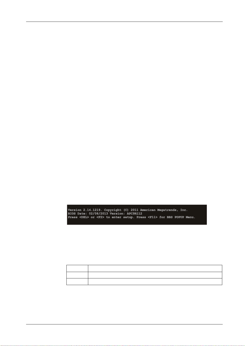
Configuration of the BIOS
BIOS Options
General Information
BIOS stands for “Basic Input Output System”. It is the most basic communication
between the user and the hardware. The BIOS used in the Industrial Personal
Computer is produced by Pro-face.
The BIOS Setup Utility lets you modify basic system configuration settings. These
settings are stored in CMOS and in an EEPROM (as a backup).
The CMOS data is buffered by a battery (if present), and remains in the Industrial
Personal Computer even when the power is turned off (24 Vdc power supply is
disconnected).
BIOS Setup and Boot Procedure
BIOS is immediately activated when switching on the power supply of the Industrial
Personal Computer or pressing the power button. The system checks if the setup
data from the EEPROM is OK. If the data is OK, then it is transferred to CMOS. If
the data is not OK, then the CMOS data is checked for validity. A message appears
if the CMOS data contains anomalies, but you can continue the boot procedure by
pressing the [F1] key. To prevent the message from appearing at each restart, open
the BIOS setup by pressing the [DEL] key and re-save the settings.
BIOS reads the system configuration information in CMOS RAM, checks the
system, and configures it using the Power On Self Test (POST).
When these preliminaries are complete, the BIOS seeks the operating system from
the data storage devices available (hard drive, floppy drive, and so on). BIOS
launches the operating system and hands over to the operating system control of
system operations.
To enter BIOS Setup, press the [DEL] key after the USB controller has been
initialized, and as soon as the following message appears on the monitor (during
POST): “Press DEL to run Setup”.
The figure shows an example BIOS startup screen:
BIOS Setup Keys
74
NOTE: When you press the [DEL] key during startup, the Main BIOS setup menu
appears (see page 77).
The following keys are enabled during the POST:
Key Function
DEL Enters the BIOS setup menu
F12 Using the [F12] key, you can boot from the network.

PS-4600 Series User Manual
Key Function
F11 Displays the boot menu. Lists all bootable devices that are connected to the
system. Use the up cursor and down cursor and then press the [Enter] key
to select the boot device.
Pause Pressing the [Pause] key stops the POST. Press any other key to resume the
POST.
NOTE: Keys input from the USB keyboard are only registered after the USB
controller has been initialized.
75

Configuration of the BIOS
You can use the following keys after entering the BIOS setup:
Key Function
F1 General help.
Cursor Moves to the previous item.
Cursor Goes to the next item.
Cursor Moves to the previous item.
Cursor Goes to the next item.
± Changes the value of the selected item.
Enter Changes to the selected menu.
PgUp Changes to the previous page.
PgDn Changes to the next page.
Start Jumps to the first BIOS menu item or object.
End Jumps to the last BIOS menu item or object.
F2/F3 Switches the colors of the BIOS setup.
F7 Resets any changes.
F9 Loads these settings for all BIOS configurations.
F10 Saves and closes BIOS setup.
Esc Exits the submenu.
76

Main Menu
Main Menu
PS-4600 Series User Manual
When you press the [DEL] key during startup, the Main BIOS setup menu appears.
The figure shows the Main menu:
The table shows the Main menu setting options:
BIOS Setting Description Setting Op-
tions
BIOS Information -––
Main BIOS Version Displays the BIOS detection. None
OEM BIOS Version Displays the OEM BIOS de-
tection.
Build Date Displays the date the BIOS
was created.
Platform Information
System Date This is the current system
System Time This is the current system
Displays information about
the chipset, CPU board and
main memory.
date setting. Buffered by a
battery (CMOS battery) after
the system has been
switched off.
time setting. Buffered by a
battery (CMOS battery) after
the system has been
switched off.
None
None
Enter Opens the Platform
Changes to the
system date
Adjustment of
the system time
Effect
information submenu.
Sets the system
date in the format
mm:dd:yyyy
(month:day:year).
Sets the system
time in the format
hh:mm:ss
(hours:minutes:seconds).
77

Configuration of the BIOS
Platform Information
The figure shows the Main submenu:
78

PS-4600 Series User Manual
The table shows the Platform Information menu setting options:
BIOS Setting Description Setting Options Effect
Processor Information
Name Displays the processor architecture. None –
Brand String Displays the processor type.
Frequency Displays the processor frequency.
Processor ID Displays the processor ID.
Stepping Displays the processor stepping ver-
Number of Processors
Microcode Revision Displays the processor microcode re-
GT Info Displays the GT information.
IGFX VBIOS Ver-
sion
Memory RC Version Displays the memory RC version.
Total memory Displays the total memory.
Memory frequency Displays the memory frequency.
PCH information
Name Displays the platform controller hub. None –
Intel PCH SKU
name
Stepping Displays the chipset stepping version.
LAN PHY Revision Displays the LAN revision.
ME FW Version Displays the Intel management engine
ME Firmware SKU Displays the Intel management stock
SPI Clock Frequency
DOFR Support Displays the DOFR support. None –
Read Status Clock
frequency
Write Status Clock
frequency
Fast Read Status
Clock frequency
sion.
Displays the processor core/threads.
vision.
Displays the IGFX VBIOS version.
Displays the chipset on the CPU
board.
firmware version.
keeping unit version.
Displays the read status clock frequency.
Displays the write status clock frequency.
Displays the read status clock frequency.
79

Configuration of the BIOS
Advanced Menu - PCI and PCIe configuration - USB Configuration
Advanced Menu
The table shows the accessible submenus from the Advanced menu:
BIOS Setting Description Setting Options Effect
Graphics Configuration Configures graphics settings. Enter Opens submenu
OEM Features Configuration of OEM features. Enter Opens submenu
PCI Configuration Configuration of PCI devices. Enter Opens submenu
PCI Configuration
PCI Express Configuration Configuration of PCI Express devices. Enter Opens submenu
PCI Express Configuration
ACPI Settings Configuration of ACPI settings. Enter Opens submenu
RTC Wake Settings Configuration of start time from being
CPU Configuration Configures the CPU settings. Enter Opens submenu
Chipset Configuration Configuration of chipset settings. Enter Opens submenu
SATA Configuration Configuration of SATA settings. Enter Opens submenu
Memory Configuration Configuration of main memory settings. Enter Opens submenu
USB Configuration Configures USB settings. Enter Opens submenu
Serial Port Console Redirection
Remote Access Configuration
CPU Board Monitor Displays the current voltage and temper-
Baseboard/Panel Features Displays device-specific information and
switched off.
Configures the keyboard/mouse options. Enter Opens submenu
Configures the remote access settings. Enter Opens submenu
ature of the processor
setup of device-specific values.
Enter Open submenu
Enter Opens submenu
Enter Opens submenu
PCI Configuration
PCI Configuration
80

Advanced PCI Configuration
The table shows the Advanced PCI Configuration setting options:
PS-4600 Series User Manual
BIOS Setting Description Setting Op-
tions
Above 4G Decoding
PCI Latency
Timer
VGA Palette
Snoop
PERR Number
Generation
SERR Number
Generation
PIRQ Routing &
IRQ Reservation
Option to enable/disable 64-bit capable devices to decode those in the address space
above 4 GB (only if the system supports
64-bit decoding).
This option controls how long (in PCI ticks)
1 PCI bus card can continue to use the
master after another PCI card has requested access.
Option to support graphics cards with 256
colors. This option should set only to Enable if colors are not displayed correctly.
Option to generate a PERR signal (parity
error detected). This signal indicates a data
parity error detected 1 cycle after PAR.
Option to generate a SERR signal (system
error).
This signal indicates a data error or other
type of system error for a special cycle
command.
Configuration of PIRQ routing. Enter Opens the submenu.
Disabled Disables this function.
Enabled Enables this function.
32...248
PCI bus
clocks
Disabled Disables this function.
Enabled Enables this function.
Disabled Disables this function.
Enabled Enables this function.
Disabled Disables this function.
Enabled Enables this function.
Enabled Enables this function.
Effect
Manually sets the value in PCI ticks.
81

Configuration of the BIOS
Advanced PIRQ Routing & IRQ Reservation
The table shows the Advanced PIRQ routing & IRQ reservation options:
BIOS Setting Description Setting Op-
tions
PIRQA Option for setting the PIRQ A. Auto Automatic assignment by the BIOS
IRQ3, IRQ4,
IRQ5, IRQ6,
IRQ10,
IRQ11,
IRQ14,
IRQ15
PIRQB Option for setting the PIRQ B. Auto Automatic assignment by the BIOS
IRQ3, IRQ4,
IRQ5, IRQ6,
IRQ10,
IRQ11,
IRQ14,
IRQ15
PIRQC Option for setting the PIRQ C. Auto Automatic assignment by the BIOS
IRQ3, IRQ4,
IRQ5, IRQ6,
IRQ10,
IRQ11,
IRQ14,
IRQ15
PIRQD Option for setting the PIRQ D. Auto Automatic assignment by the BIOS
Effect
and operating system.
Manual assignment.
and operating system.
Manual assignment.
and operating system.
Manual assignment.
and operating system.
82

PS-4600 Series User Manual
BIOS Setting Description Setting Op-
tions
PIRQE Option for setting the PIRQ E. Auto Automatic assignment by the BIOS
IRQ3, IRQ4,
IRQ5, IRQ6,
IRQ10,
IRQ11,
IRQ14,
IRQ15
PIRQF Option for setting the PIRQ F. Auto Auto matic assignment by the BIOS
IRQ3, IRQ4,
IRQ5, IRQ6,
IRQ10,
IRQ11,
IRQ14,
IRQ15
PIRQG Option for setting the PIRQ G. Auto Automatic assignment by the BIOS
IRQ3, IRQ4,
IRQ5, IRQ6,
IRQ10,
IRQ11,
IRQ14,
IRQ15
PIRQH Option for setting the PIRQ H. Auto Automatic assignment by the BIOS
IRQ3, IRQ4,
IRQ5, IRQ6,
IRQ10,
IRQ11,
IRQ14,
IRQ15
Reserve Legacy
Interrupt 1
Reserve Legacy
Interrupt 2
The interrupt reserved here is not made
available to a PCI or PCI Express device.
The interrupt reserved here is not made
available to a PCI or PCI Express device.
None No interrupt is assigned.
IRQ3, IRQ4,
IRQ5, IRQ6,
IRQ10,
IRQ11,
IRQ14,
IRQ15
None No interrupt is assigned.
IRQ3, IRQ4,
IRQ5, IRQ6,
IRQ10,
IRQ11,
IRQ14,
IRQ15
Effect
and operating system.
Manual assignment.
and operating system.
Manual assignment.
and operating system.
Manual assignment.
and operating system.
Manual assignment.
IRQx is reserved.
IRQx is reserved.
83

Configuration of the BIOS
Advanced PCI Express Configuration Menu
The table shows the Advanced PCI Express Configuration Menu options:
BIOS Setting Description Setting Op-
tions
PCI Express
Settings
PCI Express
GEN 2 Settings
PCI Express
Graphics (PEG)
port
PCI Express
Root Port 0
PCI Express
Root Port 1
PCI Express
Root Port 2
PCI Express
Root Port 3
PCI Express
Root Port 4
PCI Express
Root Port 5
PCI Express
Root Port 6
Configuration of the PCI Express settings. Enter Opens the submenu.
Configuration of the PCI Express GEN 2
settings.
Configuration of the PCI Express graphics
settings.
Configuration of the PCI Express settings
on Port 0.
Configuration of the PCI Express settings
on port 1.
Configuration of the PCI Express settings
on port 2.
Configuration of the PCI Express settings
on port 3.
Configuration of the PCI Express settings
on port 4.
Configuration of the PCI Express settings
on port 5.
Configuration of the PCI Express settings
on port 6.
Enter Opens the submenu.
Enter Opens the submenu.
Enter Opens the submenu.
Enter Opens the submenu.
Enter Opens the submenu.
Enter Opens the submenu.
Enter Opens the submenu.
Enter Opens the submenu.
Enter Opens the submenu.
Effect
84

Advanced PCI Express Settings
The table shows the Advanced PCI Express Settings options:
BIOS Setting Description Setting Options Effect
Relaxed Order-
ing
Extended Tag Option to activate/deactivate the ex-
No Snoop Option to activate/deactivate no snoop
Maximum Payload
Maximum Read
Request
1
ASPM
Extended Synch Option to set an extended synchroni-
Link Training
Retry
1) ASPM = Active State Power Management.
Option to activate/deactivate relaxed
ordering.
tended tag.
option.
Option to set the maximum surface
packet size for data transfer.
Option to set the maximum read re-
quest.
Option to set a power-saving function
(L0s/L1) for PCIE slots if they do not
require full power.
zation to improve system performance.
Option to define the number of times
the software should attempt to reroute
the link if the previous training attempt
was unsuccessful.
Disabled Disables this function.
Enabled Enables this function.
Disabled Disables this function. You can use
only 5 bits.
Enabled Enables this function. You can use
devices with 8 bits in the requester
transaction ID field.
Disabled Disables this function.
Enabled Enables this function.
Auto Automatic mapping of packet size.
128...4096 bytes Manual mapping of packet size.
Auto Automatic assignment.
128...4096 bytes Manual assignment.
Disabled The energy saving function is dis-
abled.
Auto Maximum energy savings. The ener-
gy saving function is set to L0 or L1.
Force L0s L0 mode is enabled.
Disabled Disables this function.
Enabled Enables this function.
Disabled Disables this function.
2 2 link training attempts.
3 3 link training attempts.
5 5 link training attempts.
PS-4600 Series User Manual
85

Configuration of the BIOS
BIOS Setting Description Setting Options Effect
Link Training
Timeout (µs)
Unpopulated
Links
1) ASPM = Active State Power Management.
Option to define how many microseconds the software waits before the link
training bit in the link status register is
queried.
Option to enable/disable PCIe slots
where no devices are connected.
10...1000 Time setting in µs.
Keep on link PCIe slots where no devices are con-
nected remain enabled.
Disable link PCIe slots where no devices are con-
nected are disabled to save power.
Advanced PCI Express GEN 2 Settings
The table shows the Advanced PCI Express GEN 2 Settings options:
BIOS Setting Description Setting Op-
tions
Completion Timeout
ARI Forwarding If supported by hardware and set to en-
86
In device functions that support a programmable completion timeout, the software
permits modifying the completion timeout
value.
abled, the downstream port disables its traditional device number field being 0
enforcement.
When turning a Type1 Configuration Request into a Type0 configuration request,
permitting access to Extended functions in
an ARI device immediately below the port.
Default The timeout range is between 50 µs
Shorter The software uses shorter timeout
Longer The software uses longer timeout
Disabled Disables this function.
Disabled Disables this function.
Enabled Enables this function.
Effect
and 50 ms.
ranges that are supported by the
hardware.
ranges that are supported by the
hardware.
(ARI for Alternative Routing-ID Interpretation or Alternative Requester ID
Interpretation).

PS-4600 Series User Manual
BIOS Setting Description Setting Op-
tions
AtomicOp Requester Enable
AtomicOp
Egress Blocking
IDO Request Enable
IDO Completion
Enable
LTR Mechanism
Enable
End-End TLP
Prefix Blocking
Target Link
Speed
Clock Power
Management
Compliance
SOS
Hardware Autonomous Width
Hardware Autonomous
Speed
Option to enable/disable the AtomicOp requester.
Option to enable/disable AtomicOp egress
blocking.
If supported by hardware and set to enabled, outbound AtomicOp requests via
egress ports will be locked.
If supported by hardware and set to enabled, this permits setting the number of
ID-based ordering (IDO) bit (Attribute[2])
requests to be initiated.
If supported by hardware and set to enabled, this permits setting the number of
ID-based ordering (IDO) bit (Attribute[2])
requests to be initiated.
If supported by hardware and set to enabled, this enables the Latency Tolerance
Reporting (LTR) mechanism.
If supported by hardware and set to enabled, this function block forwards the
TLPs containing End-End TLP prefixes.
If supported by hardware and set to force to
2.5 GT/s for downstream ports, this sets an
upper limit on link operational speed by redistricting the values advertised by the upstream component in its training
sequences.
When Auto is selected hardware initialized
data is used.
If supported by hardware and set to enabled, the device is permitted to use
CLKREQ number signal for power management of link clock in accordance to protocol defined in appropriate from form
factor specification.
If supported by hardware and set to enabled, it forces the LTSSM to send SKP ordered sets between sequences when
sending Compliance Pattern or Modified
Compliance Pattern.
If supported by hardware and set to disabled, it disables the hardware ability to
change the width except width size reduction for correcting unstable link operation.
If supported by hardware and set to disabled, it disables the hardware ability to
change link speed except speed size reduction for correcting unstable link operation.
Disabled Disables this function.
Enabled Enables this function. AtomicOp que-
Disabled Disables this function.
Enabled Enables this function. Outbound
Disabled Disables this function.
Enabled Enables this function.
Disabled Disables this function.
Enabled Enables this function.
Disabled Disables this function.
Enabled Enables this function.
Disabled Disables this function.
Enabled Enables this function.
Auto –
Force to
2.5 GT/s
Force to
5.0 GT/s
Disabled Disables this function.
Enabled Enables this function.
Disabled Disables this function.
Enabled Enables this function.
Disabled Disables this function.
Enabled Enables this function.
Disabled Disables this function.
Enabled Enables this function.
Effect
ries are only initiated when the bus
master enable bit is set in the command register.
AtomicOp requests via the output
port are blocked.
–
–
The PCIe device can no longer
change the link speed except to correct unstable operation.
87

Configuration of the BIOS
Advanced PCI Express Graphics (PEG) Port
The table shows the Advanced PCI Express Graphics (PEG) Port options:
BIOS Setting Description Setting Op-
tions
PCI Express
Graphics (PEG)
Port
PEG Root Port
Configuration
PEG0 Displays the mode in which the device con-
PEG0 Speed Option for setting the maximum transfer
1) ASPM = Active State Power Management.
2) This setting is only possible when PEG0 ASPM is set to ASPM L0s or ASPM L0sL1.
3) This setting is only possible when PEG1 ASPM is set to ASPM L0s or ASPM L0sL1.
4) This setting is only possible when PEG2 ASPM is set to ASPM L0s or ASPM L0sL1.
Option to set the PCI Express Graphics
port.
Option to select the root port configuration
on the 16 PCIe channels of the PEG port.
nected to the PEG0 port is operated.
rate for the PEG0 port.
Disabled Internal PEG interface devices are
Enabled Internal PEG interface devices are
Auto Internal PEG interface devices are
1 x 16 Configuration with 1 x 16.
2 x 8 Co nfiguration with 2 x 8.
1 x 8 + 2 x 4 Configuration with 1 x 8 and 2 x 4.
None –
Auto The maximum transfer rate is select-
Gen1 The maximum transfer rate is
Gen2 The maximum transfer rate is 5 GT/s.
Gen3 The maximum transfer rate is 8 GT/s.
Effect
disabled, and devices connected to
the PEG port are not detected.
enabled even if no device is detected
on the PEG port.
disabled if no device is detected on
the PEG port.
ed.
2.5 GT/s.
88

PS-4600 Series User Manual
BIOS Setting Description Setting Op-
Effect
tions
PEG0 ASPM
1
Option for setting a power-saving function
for the PEG0 port if it does not require full
power.
Disabled Disables this function.
Auto Automatic assignment by the BIOS
and operating system.
ASPM L0s Enables the L0 energy saving func-
tion.
ASPM L1 Enables the L1 energy saving func-
tion. Power consumption is lower
than with L0, but the exit latency
higher.
ASPM L0sL1 Automatic assignment of L0s or L1
power-saving function by the PCIe
device.
ASPM L0s
Option for setting the L0 power-saving
function.
Disabled Disables this function.
Root port
only
Endpoint
only
Both root
and endpoint
Enables the power-saving function
for the root port.
Enables the power-saving function
for the endpoint port.
Enables the power-saving function
for the root and endpoint ports.
2
ports
PEG1 Displays the mode in which the device con-
None –
nected to the PEG1 port is operated.
PEG1 speed Option for setting the maximum transfer
rate for the PEG1 port.
Auto The maximum transfer rate is select-
ed.
Gen1 The maximum transfer rate is
2.5 GT/s.
Gen2 The maximum transfer rate is 5 GT/s.
Gen3 The maximum transfer rate is 8 GT/s.
PEG1 ASPM
1
Option for setting a power-saving function
for the PEG1 port if it does not require full
power.
Disabled Disables this function.
Auto Automatic assignment by the BIOS
and operating system.
ASPM L0s Enables the L0 energy saving func-
tion.
ASPM L1 Enables the L1 energy saving func-
tion. Power consumption is lower
than with L0, but the exit latency
higher.
ASPM L0sL1 Automatic assignment of L0s or L1
power-saving function by the PCIe
device.
1) ASPM = Active State Power Management.
2) This setting is only possible when PEG0 ASPM is set to ASPM L0s or ASPM L0sL1.
3) This setting is only possible when PEG1 ASPM is set to ASPM L0s or ASPM L0sL1.
4) This setting is only possible when PEG2 ASPM is set to ASPM L0s or ASPM L0sL1.
89

Configuration of the BIOS
BIOS Setting Description Setting Op-
Effect
tions
ASPM L0s
Option for setting the L0 power-saving
function.
Disabled Disables this function.
Root port
only
Endpoint
only
Both root
and endpoint
Enables the power-saving function
for the root port.
Enables the power-saving function
for the endpoint port.
Enables the power-saving function
for the root and endpoint ports.
3
ports
PEG2 Displays the mode in which the device con-
None –
nected to the PEG1 port is operated.
PEG2 Speed Option for setting the maximum transfer
rate for the PEG2 port.
Auto The maximum transfer rate is select-
ed.
Gen1 The maximum transfer rate is
2.5 GT/s.
Gen2 The maximum transfer rate is 5 GT/s.
Gen3 The maximum transfer rate is 8 GT/s.
PEG2 ASPM
1
Option for setting a power-saving function
for the PEG2 port if it does not require full
power.
Disabled Disables this function.
Auto Automatic assignment by the BIOS
and operating system.
ASPM L0s Enables the L0 energy saving func-
tion.
ASPM L1 Enables the L1 energy saving func-
tion. Power consumption is lower
than with L0, but the exit latency
higher.
ASPM L0sL1 Automatic assignment of L0s or L1
power-saving function by the PCIe
device.
ASPM L0s
Option for setting the L0 power-saving
function.
Disabled Disables this function.
Root port
only
Endpoint
only
Both root
and endpoint
Enables the power-saving function
for the root port.
Enables the power-saving function
for the endpoint port.
Enables the power-saving function
for the root and endpoint ports.
4
ports
Detect non-compliant Device
Option for detecting incompatible PCI Express devices on the PEG port.
Disabled Disables this function.
Enabled Enables this function. Even incom-
patible PCI Express devices are detected on the PEG port.
De-emphasis
Control
Option for equalizing the PEG port. -6 dB -6 dB equalization.
-3.5 dB -3.5 dB equalization.
1) ASPM = Active State Power Management.
2) This setting is only possible when PEG0 ASPM is set to ASPM L0s or ASPM L0sL1.
3) This setting is only possible when PEG1 ASPM is set to ASPM L0s or ASPM L0sL1.
4) This setting is only possible when PEG2 ASPM is set to ASPM L0s or ASPM L0sL1.
90

Advanced PCI Express Root Port
UNGUARDED MACHINERY CAN CAUSE SERIOUS INJURY
Defining improper settings can cause instability or device problems. It is therefore,
we strongly recommended that these settings only be changed by experienced
users.
Failure to follow these instructions can result in death, serious injury, or
equipment damage.
PS-4600 Series User Manual
WARNING
The table shows the Advanced PCI Express Root Port options:
BIOS Setting Description Setting Op-
tions
PCI Express
Root Port x
ASPM Active State Power Management Option for
URR Unsupported Request (UR) reporting
This option is used to enable/disable the
PCI Express root port.
setting a power-saving function (L0s/L1) for
PCIE devices if not required full power.
Option for reporting unsupported requests.
Logging of error detected messages received by the root port is controlled exclusively by the Root Control Register.
Enabled PCI Express root port 1 enabled.
Disabled PCI Express root port 1 and 2 are dis-
Disabled Disables this function.
L0s Enables the L0 energy saving func-
L1 Enables the L1 energy saving func-
L0sL1 Automatic assignment of L0s or L1
Auto Automatic assignment by the BIOS
Enabled Enables this function.
Disabled Disables this function.
Effect
abled.
tion.
tion. Power consumption is lower
than with L0, but the exit latency
higher.
power-saving function by the PCIe
device.
and operating system.
91

Configuration of the BIOS
BIOS Setting Description Setting Op-
tions
FER Fatal error reporting
Option for reporting fatal errors detected.
All of the functions in a multifunction device
is monitored. The report for the root port
takes place internally inside the root complex.
NFER Non-fatal error reporting
Option for reporting non-fatal errors detected. All of the functions in a multifunction device is monitored. The report for the root
port takes place internally inside the root
complex.
CER Correctable error reporting
Option for reporting non-fatal errors detected. All of the functions in a multifunction device is monitored. The report for the root
port takes place internally inside the root
complex.
CT0 PCI Express completion timer T0
This option is used to enable/disable PCI
Express Completion Timer.
Enabled Enables this function.
Disabled Disables this function.
Enabled Enables this function.
Disabled Disables this function.
Enabled Enables this function.
Disabled Disables this function.
Enabled Enables this function.
Disabled Disables this function.
NOTE: If the system detected an ROB
(Processor Reorder Buffer) Timeout,
then this setting should be set to
enabled.
SEFE System error on fatal error
Option for generating a system error detected, if a fatal error detected is registered
by a device on the root port or on the root
port itself.
SENFE System error on non-fatal error
SECE System error on correctable error
PME SCI Option for generating an SCI if power man-
Always Enable
Port
PCIe speed Option for setting the PCI Express transfer
Assign INT to
Root Port
Option for generating a system error detected, if a nonfatal error detected is registered by a device on the root port or on the
root port itself.
Option for generating a system error detected if a correctable error detected is registered by a device on the root port or on
the root port itself.
agement is detected.
Option to keep port constantly enabled. Enabled Enables this function.
rate.
Option for enabling/disabling the IRQ for
the root port.
Enabled Enables this function.
Disabled Disables this function.
Enabled Enables this function.
Disabled Disables this function.
Enabled Enables this function.
Disabled Disables this function.
Enabled Enables this function.
Disabled Disables this function.
Disabled Disables this function.
Disabled Disables this function.
Auto Transfer rate is set automatically.
Gen1 The maximum transfer rate is
Gen2 The maximum transfer rate is 5 GT/s.
Enabled Enables this function.
Disabled Disables this function.
Effect
2.5 GT/s.
92

PS-4600 Series User Manual
BIOS Setting Description Setting Op-
tions
Extra Bus Reserved
Reserved Memory
Prefetchable
Memory
Reserved I/O Option to configure a reserved I/O range
Option for setting extra bus reserved for
bridges behind this root bridge.
Option for setting reserved memory for this
root bridge.
Option for setting perfectible memory for
this root bridge.
(4K/8K/12K/16K/20K) for this root bridge.
0...7 –
0...20 –
1...20 –
4...20 –
Advanced USB Devices
Effect
The table shows the USB Configuration menu setting options:
BIOS Setting Description Setting Op-
tions
EHCI1 (Ports 0...5) Sets USB EHCI Controller 1 for USB ports
number 0 through number 5 (USB1 through
USB4 on the system unit, USB on the monitor/panel interface and the bus unit).
EHCI2 (Ports 6...7) Sets USB EHCI Controller 2 for USB ports
number 6 through number 7 (USB5 on the
system unit, USB on the monitor/panel option).
Enabled Enables EHCI Controller 1.
Disabled Disables EHCI Controller 1.
Enabled Enables EHCI Controller 2.
Disabled Disables EHCI Controller 2.
Effect
93

Configuration of the BIOS
BIOS Setting Description Setting Op-
tions
xHCI Mode Option for setting the xHCI controller. Smart auto The USB 3.0 ports are not han-
Auto During the BIOS boot proce-
Enabled The xHCI controller is enabled
Disabled The xHCI controller is disabled.
HS Port Number 1
Switchable
HS Port Number 2
Switchable
HS Port Number 3
Switchable
HS Port Number 4
Switchable
HS Port Number 1
Switchable
Option to switch HS port 1 between xHCI
and EHCI.
Option to switch HS port 2 between xHCI
and EHCI.
Option to switch HS port 3 between xHCI
and EHCI.
Option to switch HS port 4 between xHCI
and EHCI.
Option to switch HS port 1 between xHCI
and EHCI.
Disabled Port 1 is routed to EHCI and
Enabled Port 1 is routed to xHCI. The
Disabled Port 2 is routed to EHCI and
Enabled Port 2 is routed to xHCI. The
Disabled Port 3 is routed to EHCI and
Enabled Port 3 is routed to xHCI. The
Disabled Port 4 is routed to EHCI and
Enabled Port 4 is routed to xHCI. The
Disabled Port 1 is routed to EHCI and
Enabled Port 1 is routed to xHCI. The
Effect
dled as USB 3.0 until after the
operating system has started.
Before that they are handled as
USB 2.0 ports.
If the Industrial Personal Computer is rebooted, then the
USB 3.0 ports are handled as
USB 3.0 during the boot process.
dure, USB 3.0 ports are handled as USB 2.0 ports. They
are not handled as USB 3.0
ports until after the operating
system has started and loaded
the USB 3.0 driver.
and USB 3.0 ports are always
identified as such.
All USB 3.0 ports become USB
2.0 ports.
operated with maximum USB
2.0.
corresponding SS port is enabled.
operated with maximum USB
2.0.
corresponding SS port is enabled.
operated with maximum USB
2.0.
corresponding SS port is enabled.
operated with maximum USB
2.0.
corresponding SS port is enabled.
operated with maximum USB
2.0.
corresponding SS port is enabled.
94

PS-4600 Series User Manual
BIOS Setting Description Setting Op-
tions
Per port USB Disable Control
Legacy USB support Option for setting legacy USB support. USB
Per port Legacy USB
Support Control
USB3.0 Support Option for enabling or disabling USB 3.0
XHCI Hand-off Option for setting support for operating sys-
EHCI Hand-off Option for setting support for operating sys-
Device Reset Timeout
USB Transfer Timeout
Device Power-up
Delay
Device Power-up
Delay
Overcurrent Protection
Option to enable/disable individual USB
ports.
ports do not function during startup. USB is
supported again after the operating system
has started. A USB keyboard is still recognized during the POST.
Option to enable/disable legacy support for
individual USB ports.
mode.
tems without a fully automated XHCI function.
tems without a fully automated EHCI function.
The waiting time that the USB device POST
requires after the device start command set.
Option to set the timeout value for control,
bulk, and interrupt transfer.
Option to set the maximum time to wait for a
USB device to report to the host controller.
Option to set the device power-up delay
manually.
Option to set overcurrent protection for all
USB ports.
Enter Opens the submenu.
Enabled Enables this function.
Disabled Disables this function.
Auto Automatic enabling.
Enter Opens the submenu.
Enabled All USB 3.0 ports run in USB
Disabled All USB ports run in USB 2.0 or
Enabled Enables USB 3.0 support.
Disabled Disables this function. With op-
Disabled Disables this function. With op-
Enabled Enables USB 3.0 support.
10 seconds,
20 seconds,
30 seconds,
40 seconds
1 second,
5 seconds,
10 seconds,
20 seconds
Auto The maximum time is set auto-
Manual You can enter the maximum
1...40 Value in seconds. This setting
Disabled Disables this function.
Enabled Enables this function.
Effect
3.0 mode.
1.1 mode.
erating systems that do not
have a fully automated XHCI
function, USB devices are only
operated with USB 2.0.
erating systems that do not
have a fully automated EHCI
function, USB devices are only
operated with USB 1.1.
Value in seconds.
Value in seconds.
matically. For a root port,
100 ms is set, for a hub port,
the data from the hub descriptor is used.
time manually using the option
device power-up delay in seconds.
is only possible if Device pow-
er-up delay is set to Manual.
95

Configuration of the BIOS
Advanced Per Port USB Disable Control
The table shows the Per Port USB Disable Control options:
BIOS Setting Description Setting Op-
tions
USB Port number 0
USB Port number 1
USB Port number 2
USB Port number 3
USB Port number 4
USB Port number 5
USB Port number 6
USB Port num-
*1
ber 7
Option to enable/disable the USB4 port. Disabled Disables the USB port.
Enabled Enables the USB port.
Option to enable/disable the USB2 port. Disabled Disables the USB port.
Enabled Enables the USB port.
Option to enable/disable the USB3 port. Disabled Disables the USB port.
Enabled Enables the USB port.
Option to enable/disable the USB1 port. Disabled Disables the USB port.
Enabled Enables the USB port.
Option to enable/disable the USB port on
the bus unit.
Option to enable/disable the USB port on
the monitor/panel interface.
Option to enable/disable the USB5. Disabled Disables the USB port.
Option to enable/disable the USB port on
the monitor/panel option.
*1 This setting is for Front USB.
Disabled Disables the USB port.
Enabled Enables the USB port.
Disabled Disables the USB port.
Enabled Enables the USB port.
Enabled Enables the USB port.
Disabled Disables the USB port.
Enabled Enables the USB port.
Effect
96

Advanced Per Port Legacy USB Support Control
The table shows the Per Port Legacy USB Support Control options:
PS-4600 Series User Manual
BIOS Setting Description Setting Op-
tions
USB0 Port Legacy Support
USB1 Port Legacy Support
USB2 Port Legacy Support
USB3 Port Legacy Support
USB4 Port Legacy Support
USB5 Port Legacy Support
USB6 Port Legacy Support
USB7 Port Legacy Support
Option to enable/disable legacy support for
the USB4 port.
Option to enable/disable legacy support for
the USB2 port.
Option to enable/disable legacy support for
the USB3 port.
Option to enable/disable legacy support for
the USB1 port.
Option to enable/disable USB port legacy
support on the bus unit.
Option to enable/disable USB port legacy
support on the monitor/panel interface.
Option to enable/disable USB port legacy
support for the USB5 port.
Option to enable/disable USB port legacy
support on the monitor/panel option.
Disabled Disables the USB port.
Enabled Enables the USB port.
Disabled Disables the USB port.
Enabled Enables the USB port.
Disabled Disables the USB port.
Enabled Enables the USB port.
Disabled Disables the USB port.
Enabled Enables the USB port.
Disabled Disables the USB port.
Enabled Enables the USB port.
Disabled Disables the USB port.
Enabled Enables the USB port.
Disabled Disables the USB port.
Enabled Enables the USB port.
Disabled Disables the USB port.
Enabled Enables the USB port.
Effect
97

Configuration of the BIOS
Boot Menu
Boot Menu
The table shows the Boot menu setting options:
BIOS Setting Description Setting Options Effect
Boot Device Pri-
ority
Boot Configura-
tion
Configuration of boot
order.
Configuration of boot
properties.
Enter Opens the submenu Boot Device
Priority (see page 99).
Enter Opens the submenu Boot Config-
uration (see page 99).
Boot Priority Selection Submenu
98

Boot Device Priority Settings
The table shows the Boot Priority Selection setting options:
BIOS Setting Description Setting Options Effect
Boot Priority Se-
lection
You can define the
drive used to boot up
the machine.
Device based
NOTE: Only devices that are
recognized by the system are
listed. You can change the
sequence of items in the
device list.
Type based
NOTE: You can change the
sequence of items in the
device list. You can add to the
list device types that are not
connected.
1st Boot Device Use this option to de-
2nd Boot Device
3rd Boot Device
4th Boot Device
5th Boot Device
6th Boot Device
7th Boot Device
8th Boot Device
fine the boot drive.
Disabled, SATA 0 Drive, SATA 1
Drive, SATA 2 Drive, SATA 3 Drive,
USB Floppy, USB Hard disk, USB
CDROM, Onboard LAN, External
LAN, Other BEV Device.
Select the desired boot sequence.
PS-4600 Series User Manual
Boot Configuration Submenu
The table shows the Boot Configuration setting options:
BIOS Setting Description Setting Op-
tions
PXE Option
ROM Launch
Policy
Option to boot from PXE option ROM. Do not launch Does not boot from PXE option ROM.
UEFI ROM only Boots from UEFI ROM.
Legacy ROM
only
Effect
Boots from legacy ROM.
99

Configuration of the BIOS
BIOS Setting Description Setting Op-
tions
Storage Option
ROM Launch
Policy
Video Option
ROM Launch
Policy
Option ROM
Messages
Boot Logo Option for setting the boot logo. Disabled The boot logo is not displayed.
Enter Setup If
No Boot Device
Enable Popup
Boot Menu
Bootup NumLock State
GateA20 Active Defines how memory above 1 MB is
INT19 Trap Response
Power Loss
Control
Option to boot from storage option
ROM.
Option to boot from video option ROM. Do not launch Does not boot from video option ROM.
Option to display option ROM messages during POST.
Option to set how long the setup activation key (key to enter BIOS) is displayed.
Option to enable/disable the popup
boot menu.
Option to configure the numeric keypad when the system is booted.
accessed.
Sets the BIOS reaction on INT19 trap-
ping by option.
Determines if the system is On/Off following power loss.
Do not launch Does not boot from storage option
UEFI ROM only Boots from UEFI ROM.
Legacy ROM
only
UEFI ROM only Boots from UEFI ROM.
Legacy ROM
only
Force BIOS Option ROM messages are displayed
Keep current Option ROM messages are not dis-
Enabled The boot logo is displayed.
Auto The boot logo is displayed.
1...65534 The setup activation key is shown for x
Yes The setup menu is displayed.
Yes Enables this function. Press F11 during
No Disables this function. It is not possible
On Numeric keypad is enabled.
Off Only the cursor functions of the numer-
Upon request GA20 is disabled.
Always GA20 is not disabled.
Immediate The trap is executed right away.
Postponed The trap is executed during legacy
Remain off Industrial Personal Computer stays off.
Turn off Turns on the Industrial Personal Com-
Last state Enables the previous state.
Effect
ROM.
Boots from legacy ROM.
Boots from legacy ROM.
during POST.
played during POST.
seconds.
POST to select a boot device.
to select a boot device during POST.
The devices boot in the configured boot
order.
ical keypad are activated.
boot.
puter.
100
 Loading...