


E-1
WARNING
• When inserting the Compact Panel Computer PS-3700A(Pentium®4M-1.7GHz Model) (hereafter
referred to as the "PS-A")'s power cord into the PS-A's AC Connector, check first that the PS-A's
power supply is completely turned OFF, via a breaker, or similar unit.
• Before either plugging in or unplugging a board or interface connector, be sure to turn the PS-A’s
power OFF.
• Whenever changing the Backlight, to prevent electric shocks and burns, be sure to turn OFF the
PS-A's power and wear protective gloves.
• After the PS-A’s backlight burns out, unlike the PS-A’s “Standby Mode”, the touch panel is still
active. If the operator fails to notice that the backlight is burned out and touches the panel, a
potentially dangerous machine miss-operation can occur.
If your PS-A's backlight suddenly turns OFF, use the following steps to determine if the
backlight is actually burned out.
1) If your PS-A is not set to "Standby Mode" and the screen has gone blank, your backlight is
burned out.
2) Or, if your PS-A is set to Standby Mode, but touching the screen does not cause the
display to reappear, your backlight is burned out.
• Do not open or remodel the PS-A unit, since it may lead to a fire or electric shock.
• Do not use power beyond the PS-A's specified voltage range. Doing so may cause a fire or an
electric shock.
• Do not use the PS-A in an environment where flammable gases are present, since operating the
PS-A may cause an explosion.
• The PS-A uses a lithium battery for backing up its internal clock data. If the battery is incorrectly
replaced (i.e. its + and - sides are reversed), the battery may explode. When changing the
battery, please contact your local PS-A distributor.
• Do not use the PS-A unit as a warning device for critical alarms that can cause serious operator
injury, machine damage or production stoppage. Critical alarm indicators and their control/activator units must be designed using stand-alone hardware and/or mechanical interlocks.
• To prevent operator injury or machine damage, be sure to design your machine operation system so that the machine will not malfunction due to a communication fault between the PS-A
and its host controller.
• Do not use PS-A touch panel switches in life-related or important disaster prevention situations. For
safety related switches, such as an emergency switch, be sure to use a separate mechanical switch.
• The PS-A is not appropriate for use with aircraft control devices, aerospace equipment, central
trunk data transmission (communication) devices, nuclear power control devices, or medical life
support equipment, due to these devices inherent requirements of extremely high levels of
safety and reliability.
• When using the PS-A with transportation vehicles (trains, cars and ships), disaster and crime
prevention devices, various types of safety equipment, non-life support related medical devices,
etc. redundant and/or failsafe system designs should be used to ensure the proper degree of
reliability and safety.
WARNINGS
T o pr event this unit from malfunctioning :
• In order to extend the lifetime of the hard disk, Pro-face recommends you set the Windows [Control panel]-[Power Management option]-[Turn off hard disks] selection to turn the hard disk off
when the unit is not being operated. A setting of 5 minutes is recommended.
• Do not strike the PS-A's touch panel with a hard or heavy object, or press on the touch panel with
excessive force, since it may damage the display.
• Do not install the PS-A where the temperature will exceed its specified range.
• Be sure that water, liquids or metal particles do not enter the PS-A, since it may cause a malfunction or a short circuit.
• Avoid installing the PS-A where sudden, large changes in temperature may occur . These changes
may cause condensation to form inside the unit, possibly causing a malfunction.
• To prevent excessive heat from building up inside the PS-A, do not install it where its ventilation
holes may be blocked. Also, do not install or store the PS-A near high temperature equipment.
• Do not install or store the PS-A in direct sunlight or where high levels of dust exist.
• Since the PS-A is a precision instrument, do not install or store it where either strong shocks or
excessive vibration may occur.
• Do not install or store the PS-A in an area containing chemicals or chemical fumes.
• Do not use paint thinner or organic solvents to clean the PS-A's case or screen.
• Due to the danger of unforeseeable accidents, back up all PS-A data regularly.
• After turning this unit OFF, be sure to wait a few seconds before turning it ON again. If the unit is
started too soon, it may not start up correctly.

E-2
The PS3700A-T41-ASU-P41 is a UL/CSA listed product (UL File No. E220851). Please pay
special attention to the following instructions when applying for UL/CSA approval for machinery
which includes this PS-A unit.
The PS-A conforms as a component to the following standards:
UL508 Industrial Control Equipment
CAN std C22.2 No.14-1995, CAN/CSA22.2 No.60950
PS3700A-T41-ASU-P41 (UL Registration Model No.:3180046-01)
- Equipment with a PS-A unit mounted in it requires UL/CSA evaluation for the combination of the PSA and equipment.
- The PS-A must be used as a built-in component of an end-use product.
- Use the PS-A indoors only.
- When connecting the PS-A’s power cord, be sure to use a cord that is appropriate for the current
and voltage used and that has conductive wires that are 0.75 mm2 or larger.
- When using the PS-A in an end-use product, be sure to install the PS-A unit's power cut-off
switch where the operator can easily reach it.
- Danger of explosion if backup battery is incorrectly replaced. Should be replaced only with
same or equivalent type recommended by the manufacturer. Dispose of used batteries according to the manufacturer’s instructions.
- Be sure the unit the PS-A is built into uses a UL508 compatible structure.
The PS3700A-T41-ASU-P41 is a CE marked, EMC compliant product.
<Complies with the following Standards>
• Safety
EN60950
• EMI
EN61000-6-4, EN55011(Group 1, Class A)
• EMS (EN61000-6-2)
EN61131-2, EN61000-4-2, EN61000-4-3, EN61000-4-4, EN61000-4-5, EN61000-4-6,
EN61000-4-8, EN61000-4-11, EN61000-4-12
• FCC
47 CFR Part15 Class A
If the following requirements are not met, the PS-A may fail to meet EN60950 standard requirements.
• The PS-A must be used as a built-in component of an end-use product.
• Use the PS-A indoors only.
• When connecting the PS-A’s power cord, be sure to use a cord that is appropriate for the
current and voltage used and that has conductive wires that are 0.75 mm2 or larger.
• When using the PS-A in an end-use product, be sure to install the PS-A unit's power cut-off
switch where the operator can easily reach it.
• There is a danger of explosion if the backup battery is incorrectly replaced. This battery should
be replaced only with same or equivalent type recommended by the manufacturer. Dispose of
used batteries according to the manufacturer’s instructions.
• Be sure the PS-A unit's enclosure is an EN60950 approved sheet steel structure.
CE Marking Notes
UL/CSA Application Notes
DIS TRI BUTEU R C O NSEI L DEPUI S 1985
System
Email :
2 rue René Laennec 51500 Taissy France
Fax: 03 26 85 19 08, Tel : 03 26 82 49 29
hvssystem@hvssystem.com
Site web : www.hvssystem.com
Distribué par :

E-3
The following items are included in the PS-A's package. Before using the PS-A, please confirm
that all items listed here are present.
This unit has been carefully packed, with special attention to quality. However, should you find anything
damaged or missing, please contact your local PS-A distributor immediately.When you order a PS-A
unit built to your specifications, that PS-A package should include each optional item's Installation
Guide. Please use that guide to check the contents of each optional item's package.
Package Contents
PS-A Unit (1)
(PS3700A-T41-ASU-P41)
Installation Fasteners (4/set ×2 )
Installation Gasket (1)
USB Cable Clamp (1)
• Be careful when installing the PS-A not to damage the built-in HDD.
• The Power Cord included in the FP unit’s package is designed only for
AC100V or AC115V use. Any other voltage will require a different cord.
AC Power Cord Clamp (1)
CD-ROM (1)
• The CD-ROM included in this package contains a User Manual, RAS-API
Reference Manual, and PS-A Series Utility and Driver files. Please refer to
PDF manuals.
Installation Guide (1)
<This Guide>
Installation
Guide
AC Power Cord (1)

E-4
The PS-A unit's CD-ROM contains the following PDF manual files.
- Compact Panel Computer PS-3700A (Pentium® 4M - 1.7GHz Model) User Manual (psap4e.pdf )
- PS Series Type A (Pentium® 4M - 1.7GHz Model) API Reference Manual (psap4ape.pdf)
Reading a PDF file requires installation of the Adobe Corporation's Acrobat® Reader.
Acrobat
®
Reader Installation:
To install the Acrobat® Reader software, follow the steps given below.
1) This software, in the form of a self-extracting file, is located in this CD-ROM in the folder titled
[reader]. Use the Explorer software to find the file [Reader\Eng\ar505enu.exe], and double-click
on the file icon to begin the Reader installation.
2) After installation begins, follow the instructions given.
Viewing the PDF manual:
To view the PDF manual contained in this CD-ROM, follow the steps given below.
1) Use the Explorer software to locate the file [Manual\Eng\psap4e.pdf or psap4ape.pdf] in
the folder titled [Manual].
2) Double-click on the PDF file's icon. Acrobat® Reader will automatically start and the first
page of the PDF manual will appear.
About The Manual

E-5
1 Part Names
1 : Display / Touch Panel
2 : Power Lamp LED (POWER)
10
1
12
15
14
18
16
21
20
19
22
3
4
7
11
13
17
2324
25262728 29
Top
Bottom
Sides
Rear
Front
2
5
6
LED PS-A Status
Green
Normal Operat ion
(Power On)
Orange
Sy st em Monitor Error
Touch Panel Self Test Erro
r
Orange/Red Backlight is not functioning
3 : IDE Access Lamp
LED PS-A Status
Green Current ly us ing I DE I /F
4 : Front Packing
5 : Hardware Reset Switch (RESET)
6 : USB Connector (1 port)
[USB Ver. 1.1 compatible]
*1
7 : Arm Attachment Screw Holes
[VESA 75mm]
8 : Power Switch
9 : Expansion Board Support
10 : FD Drive
11 : CD-ROM Drive
12 : PCMCIA Connectors (PCMCIA)(2 ports)
13 : Rear Cover
14 : Mouse Connector (MOUSE)
15 : Keyboard Connector (KEYBOARD)
16 : Expansion Slot
17 : LAN Connector (LAN)
[10 BASE-T /100 BASE-TX]
18 : USB Connectors (2 ports)
[USB Ver. 2.0 compatible]
19 : RS-232C Connector (COM1)
[+5V/RI Changeover]
20 : RS-232C Connector (COM2)
[+5V/RI Changeover]
21 : RS-232C Connector (COM3)
[RS-422/RS-485 Changeover]
22 : RS-232C Connector (COM4)
23 : Line Input Connector (LINE IN)
24 : Speaker Output Connector
(SPEAKER)
25 : Mike Input Connector (MIC IN)
26 : Printer Connector (LPT1)
27 : Cooling FAN
28 : CF Card Slot
29 : AC Inlet Connector
9
8
*1 USB HUB and USB Ver. 2.0 compatible devices cannot be connected.

E-6
Unit:mm [in]
2 Dimensions
Front
Top
100 [3.94]
282 [11.10]
5 [0.20]
395 [15.55]
294 [11.57]
383 [15.08]
Side
• Prior to attaching peripheral units to the PS-A, be sure the PS-A’s power
cord is disconnected from the main power supply.
• To prevent an electrical shock, be sure to disconnect the PS-A’s power cord
from the power supply before connecting the cord or any peripheral devices to the PS-A.
PS-A Unit
External Dimensions
(with Installation Fasteners installed)
100 [3.94]
160 [6.30]
5 [0.20]
394.8 [15.54]
404.8 [15.94]
Bottom
165 [6.50]
Front
Right Side
293.8 [11.57]
303.8 [11.96]
Left Side
Top
Unit:mm [in]
160 [6.30]
160 [6.30]

E-7
Electrical
Environment
3 General Specifications
• When using any of the PS-A’s optional devices, be sure to check
that device’s specifications for any special conditions or cautions that
may apply to its use.
• Be aware that not only does the Hard Disk have a fixed lifetime,
but that accidents can always occur. Therefore, be sure to back up
your Hard Disk’s data regularly, or prepare another Hard Disk unit
that can be used for backup.
Rated Voltage A C100V / AC240V
Volta ge Supply Range AC85V to AC265V
Rat e d Fr e que nc y 50/60Hz
Allowable Volta ge Drop
1cycle or less
(pause occurrences must be more than 1 s econd apart )
Power Consum pt ion 150VA or les s
Voltage E ndura nc e
A C 1500V 20mA for 1 minute
(between charging and FG terminals)
Insulation Resistance
10MΩ or higher at DC 500V
(between charging and FG terminals)
Ambient Operating Temperature
Storage Temperature
Ambient Humidity
St or age H um idit y
Air Purity (Dust)
Pollut ion D egr e e
Corrosive Gases
When using
HDD
4.9m/s
2
at 10Hz to 25Hz in X, Y, Z direction
s
for 30 minutes
When NOT
using HDD
9.8m/s
2
at 10Hz to 25Hz in X, Y, Z direction
s
for 30 minutes
Nois e Im munity
(Impuls e N ois e)
Nois e Im munity
(First transient burst noise)
Electrostatic Discharge Immunity
Noise Voltage : 1500Vp-p (v ia noise simulator)
Pulse Dur at ion : 50 ns, 500ns, 1µs
Rise Time : 1ns
Power Line : 2kV IEC 61000-4-4
COM Port : 1 k V IEC 61000- 4- 4
4kV IEC 61000-4- 2
V ibration Resistance
Free of dust
Pollut ion Degree 2
Free of corrosiv e gas es
+5
o
C to +50 oC (W hen Us ing HDD)
0 oC to +50 oC (When NOT Using HDD)
-10
o
C to + 60 oC
10%RH to 85%RH
(Non condensing, wet bulb t emperature : 2 9oC or less)
10%RH to 85%RH
(Non condensing, wet bulb t emperature : 2 9oC or less)

E-8
• The Hard Disk lifetime given here may be reduced due to unforeseen environmental factors, however, generally speaking, the disk
should last for 20,000 hours (of operation) or approximately 5
years, whichever comes first at an operating temperature of 20
o
C
and 333 hours of operation per month. (HDD access frequency of
20% or less)
• Using the Hard Disk in an environment that is excessively hot
and/or humid will shorten the disk’s usage lifetime. A wet bulb
temperature of 29
o
C or less is recommended. This is equivalent to
the following data.
• In order to extend the lifetime of the hard disk, Pro-face recom-
mends you set the Windows [Control panel]-[Power Management
option]-[Turn off hard disks] selection to turn the hard disk off
when the unit is not being operated. A setting of 5 minutes is
recommended.
• When using CD-ROM Drive, be sure to use the PS-A unit where
no excessive vibration. It causes data read error.
* 1 The front face of the PS-A unit, installed in a solid panel, has been tested using condi-
tions equivalent to the standard shown in the specification . Even though the PS-A unit’s
level of resistance is equivalent to this standard, oils that should have no effect on the
PS-A can possibly harm the unit. This can occur in areas where either vaporized oils are
present, or where low viscosity cutting oils are allowed to adhere to the unit for long
periods of time. If the PS-A’s front face protection sheet becomes peeled off, these conditions can lead to the ingress of oil into the PS-A and separate protection measures are
suggested. Also, if non-approved oils are present, it may cause deformation or corrosion
of the front panel’s plastic cover. Therefore, prior to installing the PS-A, be sure to
confirm the type of conditions that will be present in the PS-A’s operating environment.
If the installation gasket is used for a long period of time, or if the unit and its gasket are
removed from the panel, the original level of the protection cannot be guaranteed. To
maintain the original protection level, Pro-face recommends that you replace the installation gasket regularly.
Structural
Temperature Humi dity
at 35
o
C no higher than 64%RH
at 40
o
C no higher than 44%RH
Grounding 100
Ω
or less, or your country’s applicable standard
Ratings
*1
Equivalent to IP65f (JEM 1030)
(When Not Using front-face USB Port unit)
Design Type: Modular
Installation m ethod: Panel / VESA Arm
Cooling Method Via Cooling Fans (for Unit/ for CPU)
Weight Approx. 8.0kg (17.6Ib)
Dime nsions ( W x H x D) 395 mm [15.55 in] x 294 mm [11.57 in.] x 100 mm [3.94 in.]

E-9
Serial Interface (COM1,COM2,COM3,COM4)
RS-232C Interface (COM1, COM2, COM3, COM4)
15
69
4 Interfaces
Pin A rr a nge m e nt PIN# Signal Condition Direc tion
1 CD Carrier Detect Input
2 RXD Receiv e Dat a Input
3 TXD Send Data Output
4 DTR Data Terminal Ready Output
5 GND Signal Ground 6 DSR Data Set Ready Input
7 RTS Request S end Output
8 CTS Clear Send Input
9 RI / 5V Ring Indicate In/Output
FG FG Frame Ground -
RS-422 Interface (COM3)
Pin# Signal Condition Direction
1 RXA Receive Dat a (+ ) Input
2 RXB Receive Data (-) Input
3 TXA Send Data (+) Output
4 NC No Connection 5 GND Ground 6 NC No Connection 7 TXB Send Data (-) Output
8 NC No Connection 9 NC No Connection -
FG FG Frame Ground -
RS-485 Interface (COM3)
Pin# Signal Condition Direction
1 DATA+ Send/Receiv e Data (+) In/ Out p ut
2 DATA- Send/Receive Data (-) In/Output
3 NC No Connection 4 NC No Connection 5 GND Signal Ground 6 NC No Connection 7 NC No Connection 8 NC No Connection 9 NC No Connection -
FG FG Frame Ground -

E-10
Switches
The following switch settings corresponding to each Serial Interface need to be
signified. To set the switches, remove the PS-A’s Rear Cover and locate the following switches, next to the PS-A’s circuit board. For information about attach-
ing/removing the Rear Cover,
5. Installation Removing and Install-
ing the Rear Cover The switches are located as follows;
COM1
PCI
AB
C
D
COM3
BAT
• COM3 and COM4 cannot be used for +5V Output.
• Do not connect any pins to COM3 [NC].
• No. 5 pin (GND) for RS-232C (COM1,COM2,COM3, COM4) is the
signal ground. Be sure to connect the GND terminal to the other
unit’s SG (signal ground) terminal.
• Be sure to confirm what settings will be used by the other device
when setting the switches. Failure to do so can result in a unit malfunction or damage.
• Whenever changing any PS-A switch settings, be sure to first turn
the PS-A’s power supply OFF. Failure to do so can cause a PS-A
malfunction.
• Connect the FG terminal line to the connector cover's PS-A connector attachment screw.
• FG and SG terminals are internally connected in the PS-A. When
connecting to another device, be sure to create an SG shorting loop
in your system.
Use inch type (#4-40UNC) threads to hold the cable's set (attachment) screws
in place.
RI
5
V
RI
5V
COM4
USB
O
N
12345678

E-11
TXD
RTS
SW4
SW5
SW7
SW6
SW8
TXA
TXB
RXA
COM3
RXB
Switch
Location
Switch Name
Compatible
I/F
Description
A +5V/RI Changeover SW COM1
B +5V/RI Changeover SW COM2
C Serial Mode Select SW COM3
8-point dip switch. Designates COM3 communication settings.
For Serial Mode Select SW details, see Table (1).
The factory settings are all OF F. (RS-232C)
D
Touch Panel's
Communication
Changeover SW
COM4
USB
Changes the Touch Panel communication method. (Serial <--->
USB) The factory setting is USB.
(If "Serial" is selected, COM4 cannot be used.)
Changes # 9 pin (RI <---> 5V).
The factory setting is RI.
Table (1) Serial Mode Select SW
( The factory settings are all OFF. Compatible I/F: COM3 )
*1 Be sure to keep the settings, "OFF".
*2 If you use termination resistance, base your setiings on your connection specifications.
The COM3 compatible Serial Mode Select Switches (SW4 to SW8) operate
as shown in the circuit diagram below.
Fig. 1 Serial Mode Select Switches (SW4 to SW8) circuit diagram
SW
No.
Description ON O FF RS-232C RS-422 RS-485
1
Used by the system Reserved Reserved
OFF
*1
OFF*1OFF
*1
2
Changes COM3's
communciation method
RS-422/RS-485 RS-232C
OFF ON ON
3
Changes COM3's
communciation method
RS-422/RS-485 RS-232C
OFF ON ON
4
Changes TX data's output
mode
TX dat a out put is
controlled v ia
the RTS signal.
TX dat a out put is
NOTcontrolled via the RTS
signal. (nor mally out put )
OFF ON/OFF ON
5
Switches t he TX termination
resist ance ON/OFF
Inserts termination
resist ance of 220Ω
between TXA and TXB.
No ter mination
OFF ON
ON/OF
F
*2
6
Switches t he RX termination
resist ance ON/OFF
Inserts termination
resist ance of 220Ω
between RX A and RXB.
No ter mination
OFF ON
ON/OF
F
*2
7
Switches t he s hor t ing of TXA
and RXA ON or OFF
Short s TXA and RX A
(RS-485 mode)
No short ing
(RS-422 mode)
OFF OFF ON
8
Switches t he s hor t ing of TXB
and RXB ON or OFF
Short s TXB and RXB
(RS-485 mode)
No short ing
(RS-422 mode)
OFF OFF ON

E-12
Keyboard / Mouse Interface
PS/2 compatible Keyboard / Mouse Interface
Ethernet Interface (10BASE-T / 100BASE-TX)
This interface complies with the IEEE802.3 Ethernet communication standard
(10BASE-T / 100BASE-TX) and uses an RJ-45 type modular jack connector (8
points).
CF Card Interface
This interface accepts a CF Card, and connects to IDE.
Electrical Specifications
O.D : Open Drain
T.S : 3 state I/O
TTL : TTL Input
D-sub 25 pin (Female)
Screw Size: (4-40): Inch Type
13 1
25 14
Pin
No.
SPP/ECP
Mode
Signal
Name
EPP
Mode
Signal
Name
Direction
Electrical
Specif.
Pin
No.
SPP/ECP
Mode
Signal
Name
EPP
Mode
Signal
Name
Direction
Electrical
Specif.
1 STRB WRITE
In/Output
O.D/T.S
*1
14 AUTOFD DSTRB
In/Output
O.D/T.S
*1
2DATA0DATA0
In/Output
O.D 15 ERROR ERROR
Input
TTL
3DATA1DATA1
In/Output
O.D 16 INIT INIT
In/Output
O.D/T.S
*1
4DATA2DATA2
In/Output
O.D 17 SLCTIN ADSTRB
In/Output
O.D/T.S
*1
5DATA3DATA3
In/Output
O.D 18 GND GND
6DATA4DATA4
In/Output
O.D 19 GND GND
7DATA5DATA5
In/Output
O.D 20 GND GND
8DATA6DATA6
In/Output
O.D 21 GND GND
9DATA7DATA7
In/Output
O.D 22 GND GND
10 ACKNLG ACKNLG
Input
TTL 23 GND GND
11 BUSY WAIT
Input
TTL 24 GND GND
12 PE PE
Input
TTL 25 GND GND
13 SLCT SLCT
Input
TTL
* 1 Pins 1, 14, 16 and 17 will become O.D when the SPP mode specification is used. If the
mode changes to ECP or EPP, these pins will become T.S
Printer Interface (LPT1)
This interface conforms to Centronics standards.

E-13
USB Interface
This interface is for connecting USB compatible devices.
The USB port on the unit's Front face is USB Ver. 1.1 compatible. USB HUB and
USB Ver. 2.0 compatible devices cannot be connected. The USB ports (2 ports) on
the unit's Bottom face are USB Ver. 2.0 compatible.
PCMCIA Interface (PCMCIA)
These interfaces (2) are used to attach a PCMCIA Type II units.
Sound Interface
This interface uses 3 mini-pin jack connectors.
Expansion Unit Interface
This interface is used to attach a PCI unit.
5 Installation
• Before installing the PS-A into a cabinet or panel, check that the instal-
lation gasket is securely attached to the unit.
• A gasket which has been used for a long period of time may have scratches
or dirt on it, and could have lost much of its water resistance. Be sure to
change the gasket at least once a year, or when scratches or dirt become visible.
• The corresponding gasket is CA3-WPG15-01.
• Be sure the gasket's seam is not inserted into any of the unit's corners,
only in the straight sections of the groove. Inserting it into a corner may
lead to its eventually tearing.
• To ensure the installation gasket's maximum level of moisture resis-
tance, be sure the gasket's seam is inserted as shown into the
panel's bottom face.
Confirm the Installation Gasket's Positioning
It is strongly recommended that you use the installation gasket.
Place the PS-A on a level surface with the display panel facing downward.
Check that the PS-A’s installation gasket is seated securely into the gasket’s groove,
which runs around the perimeter of the panel’s frame.
Gasket
Rear of PS-A unit
• When installing the PS-A unit, or when attaching an optional item to the PS-A
unit, do not hold the PS-A unit by its rear-face fan cover while performing the
work. Doing so may damage the fan cover or cause the cover to fall off.

E-14
Installation
Fastener
Panel
PS-A
• Do not tighten the screws with too much force, since it can damage
the PS-A unit.
• The torque necessary to create a drip-resistant seal is 0.5 N•m.
• Depending on the installation panel's thickness, etc., the number of installation fasteners used may need to be increased to provide the desired level of
moisture resistance.
Attach the Installation Fasteners from Inside the Panel
The following figures show the eight (8) insertion slot locations of the PS-A
installation fasteners. Insert the hook section into the slot and tighten the
fastener with a screwdriver, as shown.
Insertion Slots
Top View
Bottom View
Right Side Left Side
Create a Panel Cut
Insert the PS-A into the panel from the front.
under 4-R3[0.12]
Unit: mm [in.]
Panel
Panel thickness
1.6mm[0.06in] to
10mm[0.39in]
PS-A
383.5
[15.10 ]
+1
0
PS-A
Panel
+0.04
0
282.5
+1
0
+0.04
0
11.12

E-15
• To enhance the PS-A's maintainability, operability and ventilation,
allow at least 100 mm clearance between the PS-A and other objects.
(The clearance must be large enough to allow you to install or
uninstall option units and to attach connectors.)
• Standard installation for the PS-A unit is in a vertical panel. If the PS-
A unit is to be installed in a slanted panel, the panel should not incline
more than 30° from the vertical.
• If the PS-A panel is to be installed in a slanted panel that inclines
more than 30°, use forced-air cooling to ensure the ambient operation
temperature does not exceed 50° C.
• Horizontal installation (that is, rotating the panel so that one of its
sides is the base) is not supported.
Installation Requirements
(unit: mm[in.])
50
[1.97]
Attaching the PS-A to a VESA Arm or to the Wall
To attach the unit to an Arm or to a wall, use the attachment screws to attach a
commercial-type arm or wall mount adaptor to the PS-A's rear face. (Screw hole to
screw hole width: VESA 75mm)
Please refer to each device's installation guide for installation instructions.
The VESA Arm attachment screw hole dimensions are as follows;
(unit: mm[in.])
Rear Face
Insert and tighten the four (4) M4 screws. (6mm or shorter.) The torque required for
these screws is only 0.7 to 0.8 N.m.
75[2.95]
75[2.95]
50
[1.97]
50
[1.97]
50
[1.97]
50
[1.97]
50
[1.97]
50
[1.97]
E-16
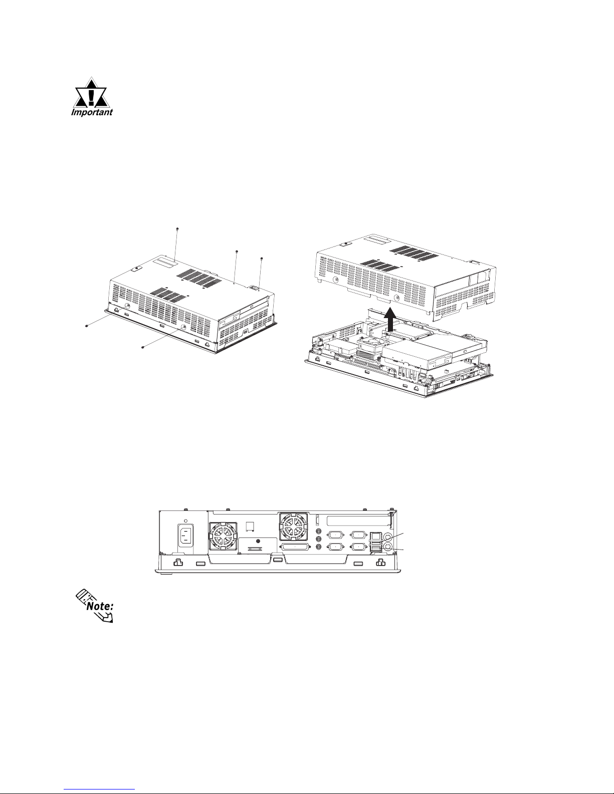
Removing and Installing the Rear Cover
• Use a screwdriver to loosen or tighten the screws. Be sure not to
tighten screws too tightly, since it may damage the equipment.
• Be careful when removing or installing any screws that they do not
fall inside the PS-A.
Lay the PS-A unit on its side and remove the five (5) cover attachment screws. Slide
the rear cover up to remove it in the direction shown. (When reattaching the screws,
use a torque of 0.5 to 0.6N•m.)
USB Cable Clamp Installation
This holder prevents the USB cable from becoming disconnected due to vibration, etc.
1) Place the PS-A unit face-down on a flat surface as shown below. Your PS-A unit has two
USB connectors.
When using only one of the USB ports, be sure to use the lower USB connector.
This allows you to securely clamp the USB cable in the cable clamp.
Upper USB Connecto
r
Lower USB Connecto
r
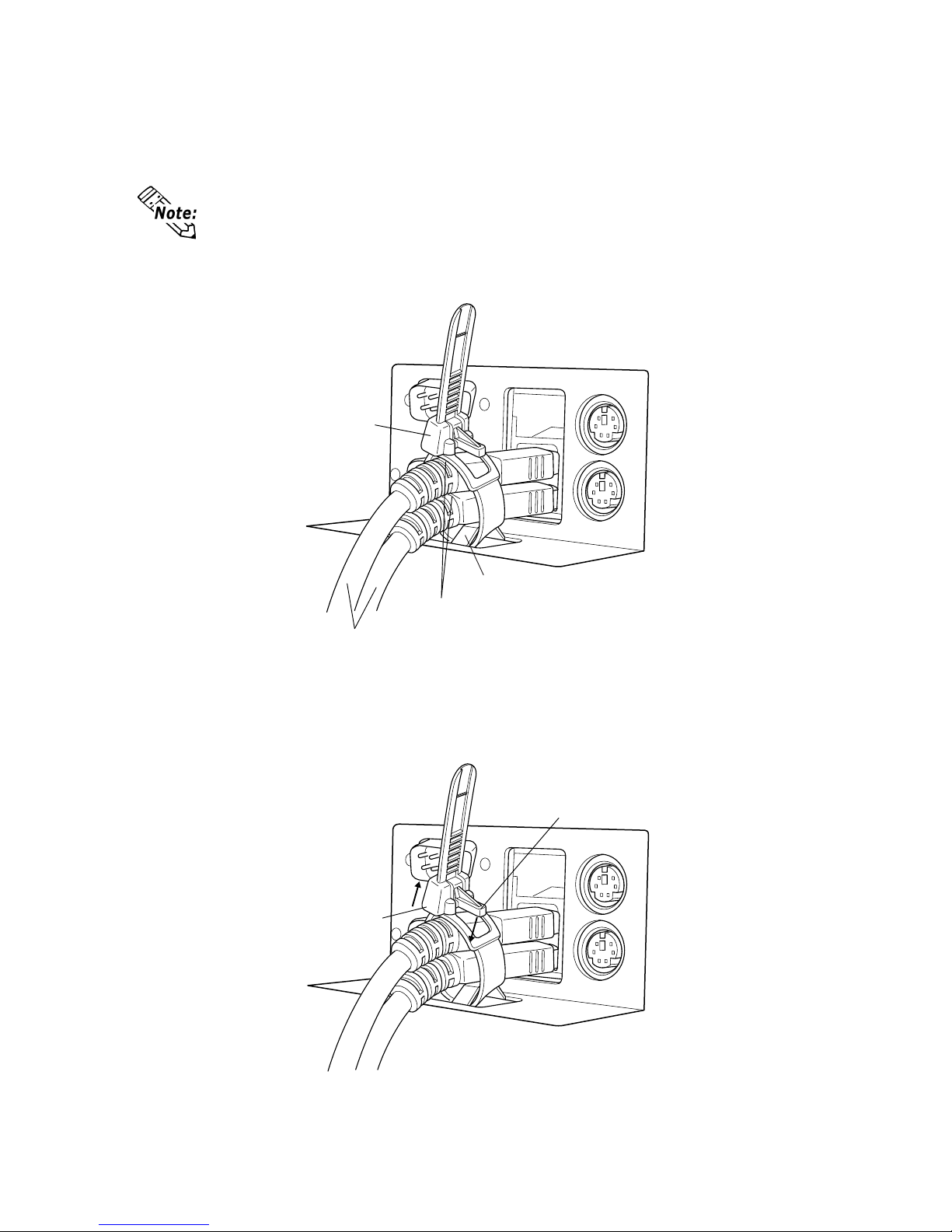
E-17
Clamp
Bridge
USB Cables
Cable Collars
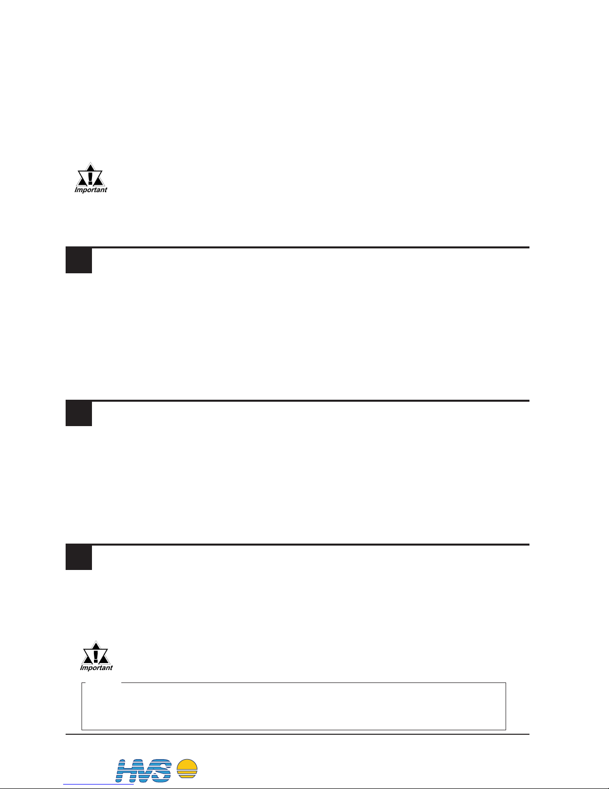
Removal
T o remove the clamp from the USB cables, push down on the clamp strap’s clip to release it while
pulling up on the clamp.
Clamp
Strap Clip
Attachment
As shown below , insert the USB Cable Clamp’s band through the Bridge. Pass the USB cables
through the Cable Clamp’s band and securely tighten the clamp band around the cables.
• Be sure the clamp is securely holding the USB cable’s plug and collar.
• Be sure the clamp is positioned as shown below, with the clamp pointing
upwards - not to the side. This is to keep the clamp from interfering with
nearby connectors and their cables.

E-18
Installing the AC Power Cord Clamp
• Be sure to connect the power cord only after confirming that the
PS-A unit rear face power switch is turned OFF.
Attaching the AC Power Cord
1) Open the AC Power Cord Clamp and insert the AC Power Cord as shown in fig. 1. Then,
close the Cord Clamp until it clicks into place and locks around the AC Power Cord Collar.
• The Cord Clamp has four teeth for locking. These are to adjust the amount of
grip used to hold the AC Power Cord Collar.
6 Wiring
• To avoid an electric shock, check that the PS-A's power supply is
turned OFF, via a breaker, or similar unit before connecting the
PS-A's power cord to the AC connector.
• To avoid the dangers of fire, electric hazards and equipment damage, be sure to use only the specified voltage when operating the
PS-A.
WARNINGS
*1 L : AC Input Terminal-live line
N : AC Input Terminal-neutral line
FG : Ground Terminal connected to the PS-A chassis
Insert the power cord (AC inlet plug) into the PS-A's bottom face AC connector.
N
L
FG
AC Connector
*1
Figure 1
AC Plug Collar
AC Plug
Cord Clamp
• The Power Cord included in the PS-A unit’s package is designed only for
AC100V or AC115V use. Any other voltage will require a different cord.

E-19
• If the power supply voltage exceeds the PS-A unit's range, connect a
voltage transformer.
• Between the line and the ground, be sure to use a low noise power supply.
If there is still an excessive amount of noise, connect a noise reducing
transformer.
Be sure any constant or insulating transformer used has a capacity of
200VA or more.
7 Power Supply Cautions
Please pay special attention to the following instructions when connecting
the AC Connector to the PS-A unit.
3) Insert the Cord Clamp Lock Pin into the PS-A’s Lock Pin Hole.
4) Adjust the Lock Pin’ s Lock T ab length until it is securely held.
Removing the AC Power Cord
1) While lifting up on the Lock Pin’ s Lock T ab Release, pull the AC Plug, Plug Collar and Cord
Clamp backwards to disconnect it from the PS-A.
2) Open the Cord Clamp and remove the AC Power Cord from the Cord Clamp.
Figure 2
2)
3)
4)
Cord Clamp Lock Pin
Lock Pin Hole
Lock Tab Release
Cord Clamp
AC Plug
AC Plug Collar
2) Connect the AC plug to the PS-A’ s AC connector, as shown in fig. 2.
AC Connector
E-20
10 Replacing the Backlight
9 Input/Output Signal Line Cautions
• Input and Output signal lines must be separated from the power control cables
for operational circuits.
• If this is not possible, use a shielded cable and the shield should be grounded.
• To improve noise immunity, it is recommended to attach a ferrite core to the
power cord.
Using any backlight other than the model written above may
cause an accident or PS-A unit malfunction.
8 Grounding Cautions
• When attaching a wire to the PS-A's bottom face FG terminal, (on the AC
Connector), be sure to create an exclusive ground.
*1
• FG and SG terminals are internally connected in the PS-A. When connecting
to another device, be sure to create an SG shorting loop in your system.
*1 Use a grounding resistance of 100Ω, a wire of 2mm2 or thicker, or your country's
applicable standard.
• Input and Output signal lines must be separated from the power control cables
for operational circuits.
• To increase the noise resistance, be sure to twist the ends of the power cord
before connecting it to the PS-A unit.
• The PS-A unit's power cord should not be bundled with or kept close to main
circuit lines (high voltage, high current), or input/output signal lines.
• Connect a surge absorber to handle power surges.
• Ground the lightning surge absorber and the PS-A separately.
• Select a lightning surge absorber which will not exceed the allowable circuit voltage, even when the voltage rises to the maximum.
• To reduce noise, make the power cord as short as possible.
Note
Please be aware that Digital Electronics Corporation shall not be held
liable by the user for any damages, losses, or third party claims arising
from the uses of this product.
The PS-A unit's backlight is user replacable. For an explanation of how to replace
the PS-A's backlight, please refer to the Installation Guide which comes with the
replacement backlights (sold separately). The corresponding backlight is CA3BLU15-01.
DIS TRI BUTEU R C O NSEI L DEPUI S 1985
System
Email :
2 rue René Laennec 51500 Taissy France
Fax: 03 26 85 19 08, Tel : 03 26 82 49 29
hvssystem@hvssystem.com
Site web : www.hvssystem.com
Distribué par :
 Loading...