


Compact Panel Computer
PS-3700A
TM
(Eden
ESP6000 - 667MHz Model)
User Manual

Introduction
The PS-3700A (EdenTM ESP6000-667MHz Model) (PS-A) of Compact Panel Computers are multipurpose factory automation (F A) computers, which embody Pro-face’s latest, cost-effective architecture. Before using the PS-A, read this
manual thoroughly to familiarize yourself with the PS-A’s operation procedures and functions.
NOTE
1. It is forbidden to copy the contents of this manual in whole, or in part, without the permission of the Digital Electronics Corporation.
2. The information in this manual is subject to change without notice.
3. This manual was written with care; however, if you should find any error or omissions, please contact Digital
Electronics Corporation and inform them of your findings.
4. Regardless of the above clause, Digital Electronics Corporation shall not be held responsible for any damages or
third-party claims for damages or losses resulting from the use of this product.
Product names used in this manual are the trademarks of their respective manufacturers.
© Copyright 2003 Digital Electronics Corporation. All rights reserved.
1
Essential Safety Precautions
This manual includes the following cautions concerning procedures that must be followed to operate the PS-A correctly
and safely. Prior to operating the PS-A, be sure to read this manual and any related materials thoroughly to understand the
correct operation and functions of this unit.
Safety Icons
To allow you to use the PS-A correctly, throughout this manual, the following icons are provided next to operations
requiring special attention. These icons are used to describe the following situations:
Failure to fully comply with points indicated by this symbol may result in death or
serious injury.
Failure to fully comply with points indicated by this symbol may result in injury or
equipment damage.
Indicates actions or procedures that should NOT be performed.
Indicates actions or procedures that MUST be performed to ensure proper operation.
To avoid the possibility of an electric shock, be sure to disconnect the power cord to the PS-A before connecting it to the main power supply.
A fire or electrical shock may occur if voltages used with the PS-A are beyond the specified range. Be
sure to use only the specified voltage.
Before opening the PS-A’s protective cover, be sure to turn the unit's power OFF. This is becau se the PSA's internal parts carry high voltages.
To avoid fires or electrical hazards, do not modify the PS-A in any way.
Do not create touch panel switches that are used to either control or to ensure the safety of equipment
and personnel. Mechanical switches, such as an emergency stop switch, a deadman (two-handed) start
switch, etc., must be installed and operated via a separate control system.
Do not create touch panel switches which could possibly endanger the safety of humans and equipment.
This is due to the possibility of a malfunction in the PS-A or its cable(s), causing the output of a signal that
could result in a major accident. All of a system's major, safety-related switches should be designed to be
operated separately from the PS-A.
2
After the PS-A ’s backlight burns out, unlike the PS-A’s “S t andby Mode”, the touch panel is still active. If the
operator fails to notice that the backlight is burned out and touches the panel, a potentially dangerous
machine operation error can occur.
If your PS-A’s backlight suddenly turns OFF, use the following steps to determine if the backlight is actually burned out.
1) If your PS-A is not set to “Standby Mode” and the screen has gone blank, your backlight is burned out.
2) Or, if your PS-A is set to St andby Mode, but touching the screen does not cause the display to reappear, your backlight is burned out.
If metal particles, water or other types of liquids contact any of the PS-A’s internal parts, immediately turn
the unit’s power OFF, unplug the power cord, and contact either your PS-A distributor or the Digital Electronics Corporation.
Read and understand Chapter 2 "Hardware Installation" thoroughly in order to select an appropriate installation location for the PS-A.
Before either plugging in or unplugging a board or interface connector, be sure to turn the PS-A’s power
OFF.
To prevent a possible explosion, do not install the PS-A in areas containing flammable gases.
The PS-A is not appropriate for use with aircraft control devices, aerospace equipment, central trunk data
transmission (communication) devices, nuclear power control devices, or medical life support equipment,
due to these devices’ inherent requirements of extremely high levels of safety and reliability.
When using the PS-A with transportation vehicles (trains, cars and ships), disaster and crime prevention
devices, various types of safety equipment, non-life support related medical devices, etc. redundant and/
or fail-safe system designs should be used to ensure the proper degree of reliability and safety.
Do not push on the PS-A’s screen too strongly, with either your finger or with a hard object. Excessive
pressure can scratch, crack or damage the screen. Also, do not use a pointed object, such as a mechanical pencil or screwdriver, to press any of the touch panel's switches, since they can damage the display.
If the screen becomes dirty or smudged, moisten a soft cloth with diluted neutral detergent, wring the cloth
well, and wipe the display. Do not use thinner or organic solvents.
Avoid exposing the PS-A to, or operating the PS-A in direct sunlight, high temperatures and humidity, and
in areas where excessive dust and vibration will occur.
Avoid using the PS-A in areas where sudden, extreme changes in temperature can occur. This may cause
condensation to form inside the unit, possibly leading to an accident.
To prevent the PS-A from overheating, be sure its air circulation vents are clear and clean, and keep the
unit's operation area well-ventilated.
Avoid operating or storing the PS-A near chemicals, or where chemicals can come into contact with the
unit.
3

When PS-A Hard Disk (HDD) data is lost:
The Digital Electronics Corporation cannot be held responsible or provide any compensation for damage(s) caused by the loss of data stored in the PS-A’s hard disk drive (HDD). It is therefore strongly suggested that all important data and software be backed up regularly to an external data backup device.
Please be aware that the Digital Electronics Corporation bears no responsibility for any damages resulting
from the customer's application of this unit's hardware or software.
Since the PS-A unit’s hard disk drive (HDD) is a consumable item, i.e. it has a limited lifetime, be sure to
back up its data regularly and prepare a spare HDD unit.
In order to extend the lifetime of the hard disk, Pro-face recommends you set the Windows [Control
panel]-[Power Management option]-[Turn off hard disks] selection to turn the hard disk off when the unit is
not being operated. A setting of 5 minutes is recommended.
To prevent file data damage, be sure to shut down the PS-A's OS before turning OFF the main power.
WAfter turning OFF the PS-A’s power, wait until the internal HDD stops spinning before turning on the
power again (approx. 5 seconds).
LCD Usage and Handling
• The PS-A’ s LCD co ntains a strong irritant. If the panel is ever cracked and the LCD’s liquid contacts your skin, be sure
to wash it with running water for at least 15 minutes. If any of this liquid should enter your eye, be sure to flush your
eye with running water for more than 15 minutes and see a doctor as soon as possible.
• The brightness of the LCD screen will depend on the screen's current display and the LCD’s contrast adjustment. Any
brightness variations that result are normal for LCD displays.
• There are minute grid-points (Dark or Light points) on the LCD surface. These points are not defects and are a part of
the PS-A unit's design.
• The displayed color will look different when viewed from an angle outside the specified view angle. This is also normal.
• When installing this unit, be sure that the screen is viewable from within the designated viewing angles. The screen
image being difficult to see from outside its recommended viewing angle is normal.
• Displaying a single screen image for long periods of time can cause an afterimage to remain on the screen. To correct
this, turn the unit OFF for 5 to 10 minutes, then ON again. This phenomenon is a common attribute of LCD displays,
and is not a defect. To prevent this effect, you can:
1) Use the Display OFF feature; if the same image is to be displayed for a long period of time.
2) Change the screen display periodically to prevent the displaying of a single image for a long period of time.
4
This manual uses the following icons:
Indicates a warning or a product limitation. Be sure to follow the instructions given with
this icon to insure the safe operation of the PS-A.
Contains additional or useful information.
Information Symbols
*
SEE
(1) (2)
PS-A
Indicates terms or items that require further explanation. See the footnote on that page.
Indicates pages containing related information.
Indicates steps used to accomplish a given task.
Be sure to follow these steps in the order they are written.
Refers collectively to the Compact Panel Computers PS-3700A (EdenTM ESP6000667MHz Model) units.
5

Package Contents
The following items are included in the PS-A’s package. Before using the PS-A, please confirm that all items listed here
are present.
PS-A
(PS3700A-T41-ASU-E66) Moisture Resistant Gasket (1)
Installation Fasteners (4/set x 2) USB Cable Clamp (1)
AC Power Cord (1) AC Power Cord Clamp (1)
CD-ROM (1) Installation Guide (1)
(PS370XA-E66 User Manual & Driver CD) (Japanese/English)
Installation
Guide
• Be careful when installing the PS-A not to damage the built-in HDD.
• The Power Cord included in the FP unit's package is designed only for AC100V
or AC115V use. Any other voltage will require a different cord.
This unit has been carefully packed, with special attention to quality . However, should you find anything damaged or missing, please contact your local PS-A distributor immediately.
• The CD-ROM included in this package contains a User Manual, API Reference Manual,
and PS-A Series Utility and Driver files.
SEE
• When you order a PS-A unit built to your specifications, that PS-A package should
include each optional item's Installation Guide. Please use that guide to check the contents of each optional item's package.
Chapter 4 Setting up Your PS-A Unit (page4-1)
6

UL/c-UL (CSA) Application Notes
PS3700A-T41-ASU-E66 unit is UL/c-UL listed product (UL File No. E220851). Please pay special attention to the following instructions when applying for UL/c-UL approval for machinery which includes any of PS-A units.
The PS-A conforms as a component to the following standards:
UL508 Industrial Control Equipment
CAN Std C22.2 No.14-1995 CAN/CSA 22.2 No.60950
PS3700A-T41-ASU-E66 (UL Registration Model No.:3280015-01)
- Equipment with a PS-A unit mounted in it requires UL/c-UL evaluation for the combination of the PS-A and equipment.
- The PS-A must be used as a built-in component of an end-use product.
- Use the PS-A indoors only.
- When connecting the PS-A’s power cord, be sure to use a cord that is appropriate for the current and voltage used and
that has conductive wires that are AWG18 or larger.
- Danger of explosion if backup battery is incorrectly replaced. Should be replaced only with same or equivalent type
recommended by the manufacturer. Dispose of used batteries according to the manufacturer’s instructions.
- Be sure the unit the PS-A is built into uses a UL508 compatible structure.
7

CE Marking Notes
PS3700A-T41-ASU-E66 unit is CE marked, EMC compliant product.
<Complies with the following Standards>
Safety
EN60950
EMI
EN61000-6-4, EN55011(Group 1, Class A)
EMS (EN61000-6-2/EN61131-2)
EN61000-4-2, EN61000-4-3, EN61000-4-4, EN61000-4-5, EN61000-4-6, EN61000-4-8, EN61000-4-1 1,
EN61000-4-12
FCC
47 CFR Part 15 Class A
If the following requirements are not met, the PS-A may fail to meet EN60950 standard requirements.
• The PS-A must be used as a built-in component of an end-use product.
• Use the PS-A indoors only.
• When connecting the PS-A’s power cord, be sure to use a cord that is appropriate for the current and voltage used and
that has conductive wires that are AWG18 or larger.
• There is a danger of explosion if the backup battery is incorrectly replaced. This battery should be replaced only with
same or equivalent type recommended by the manufacturer. Dispose of used batteries according to the manu facturer’s
instructions.
• Be sure the PS-A unit’s enclosure is an EN60950 approved sheet steel structure.
8

Contents
Introduction................................................................................................................ 1
Essential Safety Precautions.....................................................................................2
Information Symbols..................................................................................................5
Package Contents.....................................................................................................6
UL/c-UL (CSA) Application Notes............................................................................. 7
CE Marking Notes.....................................................................................................8
Contents....................................................................................................................9
CHAPTER 1 Overview
1.1 Prior to Operating the PS-A Unit.....................................................................1-2
1.2 PS-A Unit System Configuration.....................................................................1-3
1.2.1 Setting Up the Touch Panel Connection...............................................................1-4
1.2.2 Using the USB Interface (located on the front face) ....................................... ... ...1-4
1.3 PS-A Unit Part Names and Features..............................................................1-5
1.4 Interfaces........................................................................................................1-7
1.4.1 RS-232C Interface (COM1/COM2/COM3/COM4)................................................1-7
1.4.2 Printer Interface (LPT1) ......................................................................................1-10
1.5 PS-A Unit External Views and Dimensions................................................... 1-11
1.5.1 PS-A Unit............................................................................................................1-11
1.5.2 External Dimensions (with Installation Fasteners installed)................................1-12
1.5.3 Panel Cut Dimensions ........................................................................................1-13
1.5.4 Installation Fasteners..........................................................................................1-13
CHAPTER 2 Hardware Installation
2.1 Installtion.........................................................................................................2-2
2.1.1 Removing the PS-A Unit's Cover..........................................................................2-2
2.1.2 PS-A Internal View................................................................................................2-3
2.1.3 Main Memory Installation......................................................................................2-4
2.1.4 Expansion Board (PCI) Installation.......................................................................2-4
2.1.5 PCMCIA Unit Installation ......................................................................................2-6
2.1.6 USB Cable Clamp Installation...............................................................................2-7
2.1.7 CF Card Installation and Removal........................................................................2-8
2.2 Installing the PS-A Unit.................................................................................2-10
2.2.1 Installation Caution .............................................................................................2-10
2.2.2 Installation Procedures .......................................................................................2-12
9

2.3 Wiring the PS-A............................................................................................2-16
2.3.1 Connecting the Power Cord . ... ... ... .... ... ...............................................................2-16
2.3.2 Power Supply Cautions................................. .... ... ... ... .........................................2-17
2.3.3 Grounding Cautions............. ... ... ... .... ... ... ................................................ .... ... ... ..2-19
2.3.4 Cautions When Connecting I/O Signal Lines......................................................2-19
CHAPTER 3 System Setup
3.1 Setup Procedures........................................................................................... 3-2
3.2 System Parameters........................................................................................3-3
3.2.1 Standard CMOS Features................................................................. ... ... .... ..........3-3
3.2.2 IDE HDD Auto-Detection . .... ... ... ... .... ... ... ... ... .... ... ... ... .... ... ... ... ..............................3-5
3.2.3 Advanced BIOS Features............................. .... ... ... ... .... ... ... .................................3-6
3.2.4 Advanced Chipset Features.............................. ... ... ... .... ... ....................................3-9
3.2.5 Integrated Peripherals.........................................................................................3-12
3.2.6 Power Management Setup .. ... ... ... .... ... ... ... .................................................... ... ..3-16
3.2.7 PnP/PCI Configurations.......... ... ... ...................................................................... 3-18
3.2.8 IRQ Resources ....... ... ... ... .... ... ... ... .... ... ... ... ... ................................................. ... ..3-19
3.2.9 System Monitor Setup.........................................................................................3-20
3.2.10 Frequency/Voltage Control...............................................................................3-21
3.2.11 Load Fail-Safe Defaults............ ... .... ... ... ... ... .... ... ...............................................3-21
3.2.12 Load Optimized Defaults...................................................................................3-22
3.2.13 Set Supervisor Password..................................................................................3-23
3.2.14 Set User Password.................................. ... .... ... ...............................................3-23
3.2.15 Save & Exit Setup.............................................................................................3-23
3.2.16 Exit Without Saving...........................................................................................3-23
CHAPTER 4 Setting up Your PS-A Unit
4.1 CD-ROM Contents..........................................................................................4-2
4.1.1 Software........................................ .... ... ... ................................................ .... ..........4-2
4.2 Setting Up Your PS-A Unit..............................................................................4-3
4.2.1 Setup Procedures................................... ... ... .... ... ................................................ .4-3
4.2.2 Setting Up an HDD with Pre-installed OS.............................................................4-4
4.3 Installing Drivers.............................................................................................4-6
4.4 Special Application Program Features............................................................4-7
4.4.1 Uninstalling Utility Software . ... ... ... .... ....................................................................4-9
4.5 When Using Windows®2000/Windows®XP.................................................4-10
4.5.1 Automatic System Log-on Setup ......... ...............................................................4-10
4.5.2 Uninterrupted Power Supply System (UPS).......................................................4-11
4.5.3 Changing System Settings......................... ... .... ... ... ... .... ... ... ... .... ........................4-11
4.5.4 NTFS File System Conversion............................. ... ... .... ... ... ... .... ... ... ... ... .... ... ... ..4-11
10

CHAPTER 5 Monitoring Features
5.1 RAS Features .................................................................................................5-2
5.1.1 PS-A RAS Features..............................................................................................5-2
5.1.2 RAS Feature Details.............................................................................................5-3
5.1.3 RAS Feature Overview.........................................................................................5-5
5.2 System Monitor/RAS Features.......................................................................5-6
5.2.1 Setup Procedures.................................................................................................5-6
5.2.2 System Monitoring Property Settings (PSA_Wps.exe)......... .... ... ... ... ... .... ... ... ... ...5-7
5.2.3 System Monitoring Operation (PSA_Smon.exe)...................................................5-9
5.2.4 Error Messages ..................................................................................................5-12
5.3 Error Displays When Using Event Viewer.....................................................5-14
5.3.1 Error Message Display .......................................................................................5-14
5.3.2 Error Type/Location ............................................................................................5-15
5.3.3 Error Action.........................................................................................................5-15
5.4 Remote RAS.................................................................................................5-16
5.4.1 System Configuration .........................................................................................5-16
5.4.2 Installation Procedures .......................................................................................5-17
5.4.3 Setup and Preparation of the Remote RAS Feature...........................................5-17
5.4.4 Read and Write of the System Monitor/RAS Feature.........................................5-19
5.4.5 Restrictions.........................................................................................................5-22
5.5 Remote Shutdown Feature...........................................................................5-23
CHAPTER 6 Maintenance and Inspection
6.1 Regular Cleaning............................................................................................6-2
6.1.1 Cleaning the Display.......................... ... ... ... .... ... ... ... .... ... ... ... .... ... .........................6-2
6.1.2 Installation Gasket Replacement..........................................................................6-3
6.2 Cleaning the Fan Filter ...................................................................................6-3
6.3 Changing the PS-A Backlight .........................................................................6-4
6.4 Periodic Inspection Items................................................................................6-8
CHAPTER 7 Specifications
7.1 General Specifications....................................................................................7-2
7.1.1 Electrical Specifications........................................................................................7-2
7.1.2 Environment..........................................................................................................7-2
7.1.3 Structural Specifications........................................................................................7-4
7.2 Performance Specifications............................................................................7-5
7.2.1 Performance Specifications..................................................................................7-5
7.2.2 Display Functions .................................................................................................7-6
7.2.3 Expansion Slots....................................................................................................7-6
7.2.4 Clock Accuracy.....................................................................................................7-6
11

Appendices
A.1 Hardware Configuration..............................................................................App-2
A.1.1 I/O Map............................................................................................................ App-2
A.1.2 Memory Map.................................................................................................... App-3
A.1.3 Interrupt Map................................................................................................... App-4
A.2 List of Optional Devices..............................................................................App-5
Index
12

1 Overview
1. Prior to Operating the PS-A Unit
2. PS-A Unit System Configuration
3. PS-A Unit Part Names and Features
4. Interfaces
5. PS-A Unit External Views and Dimensions
1-1

Compact Panel Computer PS-3700A (Eden
TM
ESP6000-667MHz Model) User Manual
1.1 Prior to Operating the PS-A Unit
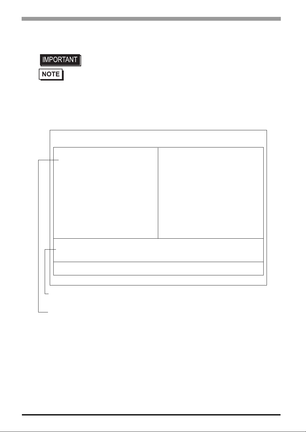
The following explanation shows the preparation steps required prior to operating the PS-A.
Connect Peripheral Devices
Connect Power
Connect the display unit and any optional devices.
SEE
Connect the PS-A unit’s power cord to AC Interconnection and turn the power switch ON.
SEE
1.2 PS-A Unit System Configuration
(page1-3) /1.3 PS-A Unit Part Names
and Features (page1-5)
2.3 Wiring the PS-A (page2-16)
[When PS-A has no preinstalled OS]
Install a commercial OS
in your PS-A. For how to
setup the OS, refer to
the manual provided
with the product.
User Manual and Driver CD Data
Install Required Device Drivers
Install Required Software
Set Up the System
[When PS-A has preinstalled OS]
Install an OS
Install PS370XA-E66
Configure the PS-A unit's BIOS.
SEE
Install all required software. For software installation instructions, refer to the manual provided
with that product.
Chapter 3 System Setup (page3-1)
1-2
Install the PS-A Unit
• After hardware setup is completed, the OS must be used to create partitions and
format (initialize) the HDD before any data or applications can be saved to the
hard disk drive. For details concerning these procedures, refer to the OS manufacturer's instruction manual.
• Whenever you turn the PS-A unit's power OFF, wait until the internal HDD stops
spinning (approximately 5 seconds) before turning the power ON again.
®
• The PS-A’s hard disk is designed for use with the Windows
®
XP. Other operating systems do not support this driver software, etc.
dows
2000 and Win-

1.2 PS-A Unit System Configuration
P
s
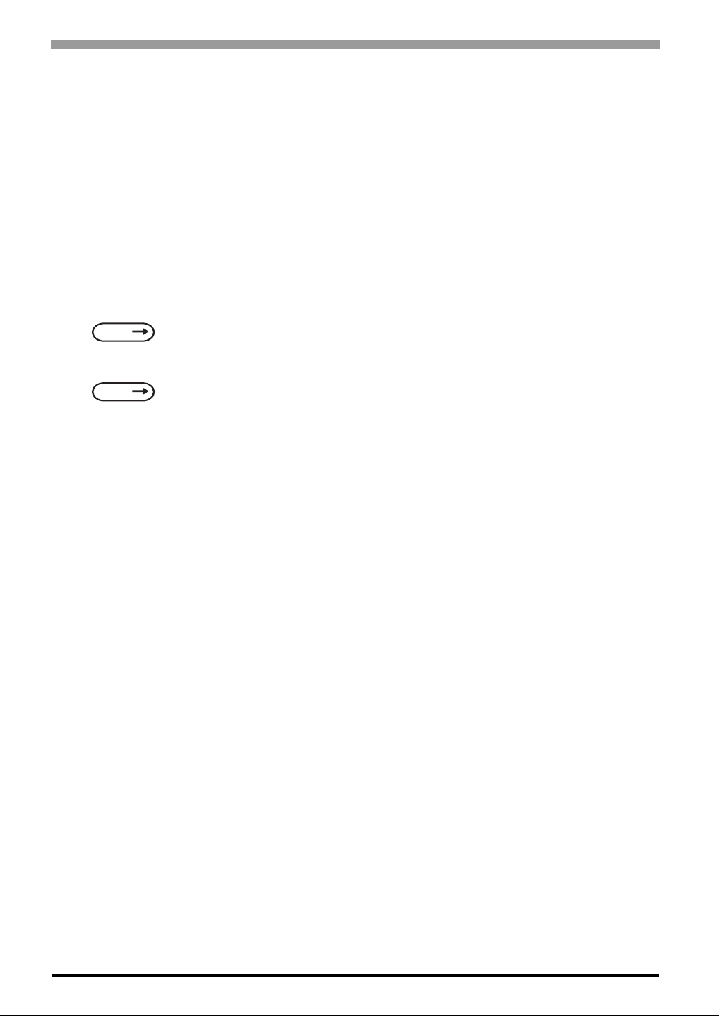
The following chart shows the range of peripheral items connected to the PS-A.
S3700A-T41-ASU-E66
IDE Connector
HDD Unit
Chapter 1 Overview
*1*2
Main Memory
Inside PS-A unit
Connector
COM1/COM2/COM3/COM4
Printer Connector
Side of PS-A unit
Front of PS-A unit
Bottom of PS-A unit
LAN Connector
Line Input Connector
Speaker Out Connector
Mike Input Connector
USB Connectors
(2 ports)
Mouse Connector
Keyboard Connector
10BASE-T/100BASE-TX
Cable (commercial type)
RS-232C Cable
Printer Cable
(commercial type)
Pin-jack Cable
(commercial type)
USB 1.1 Compatible
Peripherals(commercial type)
PS/2 Mouse
PS/2 Keyboard
Main Memory Module
Peripherals
(commercial type)
Hub
Central Network Line
*1*2
Peripherals
(commercial type)
Speaker
Mike
CF Card Slots
(TYPE2, 1 port)
Expansion Slot
PCMCIA Connector
(2 ports)
CD-ROM Drive
FD Drive
USB Connector
(1 port)
*1 Built-in accessory only
*2 The Digital Electronics Corporation's optional devices used with the PS-A. Please refer to A.2 List of Optional Device
CF
CF Cards
Peripherals
(commercial type)
PCMCIA Card
(commercial type)
CF Card Adaptor
(commercial type)
(commercial type)
USB 1.1 Compatible
Peripherals(commercial type)
*2
CF
*2
CF Cards
*2
• This diagram shows only the PS-A’ s internal layout and connectable devices. The
user’s actual design may differ.
1-3

Compact Panel Computer PS-3700A (Eden
TM
ESP6000-667MHz Model) User Manual
1.2.1 Setting Up the Touch Panel Connection
The connection method used can be via either a serial (RS-232C) or USB interface. Depending on the type of
Tou ch Panel connection used, the OS types that can be used will vary.
DIPSW1
Changes the Touch Panel Communication method (Serial ↔ USB). For the details about the switch,
SEE
1.4.1 RS-232C Interface (COM1/COM2/COM3/COM4) (page1-7)
• Whenever changing any PS-A switch settings, be sure to first turn the PS-A’s
power supply OFF. Failure to do so can cause a PS-A malfunction.
• If “Serial” is selected, COM4 cannot be used.
Mouse Emulator V2(PL-TD000)
When installing the Mouse Emulator, be sure to select USB.
1.2.2 Using the USB Interface (located on the front face)
• When using multiple commercial-type USB peripheral devices, be sure to use a
commercial-type USB HUB. However, USB HUBS cannot be connected to each
other.
(Connection example)
PS-A
1-4
USB HUB

1.3 PS-A Unit Part Names and Features
1 : Display / Touch Panel
2 : Power Lamp LED (POWER)
2
1
3
4
Chapter 1 Overview
LED PS-A Status
Green
Orange
Orange/Red Backlight is not functioning
Normal Operation
(Power On)
System Monitor Error
Touch Panel Self Test Error
7
8
14
15
Front
Rear
10 12
11
13
22
18 20 25 26 28 29
16 21 23
19 24 27
17
Side
Top
Bottom
3 : IDE Access Lamp
5
6
4 : Front Packing
5 : Hardware Reset Switch (RESET)
9
6 : USB Connector (1 port)
7 : Arm Attachment Screw Holes
(VESA 75mm)
8 : Power Switch
9 : Expansion Board Support
10 : FD Drive
11 : CD-ROM Drive
12 : PCMCIA Connectors (PCMCIA)(2 ports)
13 : Rear Cover
14 : Mouse Connector (MOUSE)
15 : Keyboard Connector (KEYBOARD)
16 : Expansion Slot
17 : LAN Connector (LAN)
(10 BASE-T /100 BASE-TX)
18 : USB Connectors (2 ports)
19 : RS-232C Connector (COM1)
20 : RS-232C Connector (COM2)
21 : RS-232C Connector (COM3)
22 : RS-232C Connector (COM4)
23 : Line Input Connector (LINE IN)
LED PS-A Status
Green Currently using IDE I/F
Pressing this switch re-starts the PS-A unit.
Provides a USB 1.1 compatible connection.
Connect a USB connectable device here.
This cover is removed when installing an HDD unit,
main memory , or Expansion unit (PCI).
Connect a PS/2-compatible mouse here.
Connect a PS/2-compatible keyboard here.
Provides a USB 1.1 compatible connection.
Connect a USB connectable device here.
[+5V/RI Changeover]
[+5V/RI Changeover]
[RS-485 Changeover]
1-5

Compact Panel Computer PS-3700A (Eden
• Prior to attaching peripheral units to the PS-A, be sure the PS-A’s power cord is
disconnected from the main power supply.
• To prevent an electrical shock, be sure to disconnect the PS-A’s power cord from
the power supply before connecting the cord or any peripheral devices to the
PS-A.
TM
ESP6000-667MHz Model) User Manual
24 : Speaker Output Connector (SPEAKER OUT)
25 : Mike Input Connector (MIC IN)
26 : Printer Connector (LPT1)
27 : Cooling FAN
28 : CF Card Slot
29 : AC Inlet Connector
1-6
1.4 Interfaces
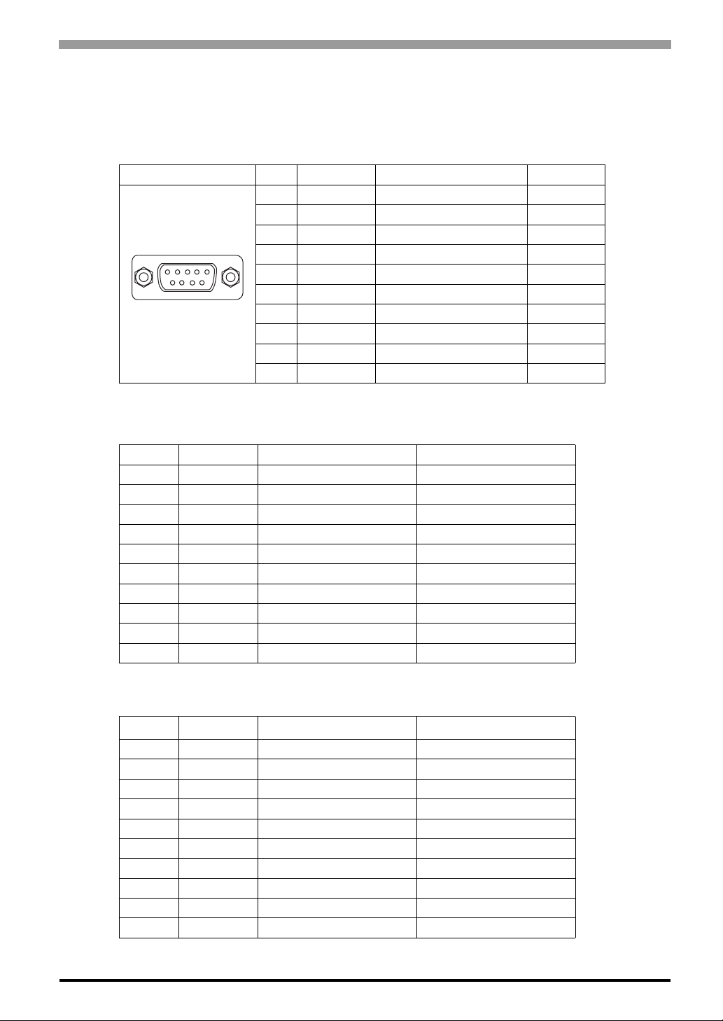
1.4.1 RS-232C Interface (COM1/COM2/COM3/COM4)
RS-232C Interface (COM1/COM2/COM3/COM4)
Pin Arrangement PIN# Signal Condition Direction
1 CD Carrier Detect Input
2 RXD Receive Data Input
1
RS-422 Interface (COM3)
Pin# Signal Condition Direction
1 RXA Receive Data (+) Input
2 RXB Receive Data (-) Input
3 TXA Send Data (+) Output
4 NC No Connection 5 GND Ground 6 NC No Connection 7 TXB Send Data (-) Output
8 NC No Connection 9 NC No Connection -
FG FG Frame Ground -
5
6
9
3 TXD Send Data Output
4 DTR Data Terminal Ready Output
5 GND Signal Ground 6 DSR Data Set Ready Input
7 RTS Request Send Output
8 CTS Clear Send Input
9 RI / 5V Ring Indicate In/Output
FG FG Frame Ground -
Chapter 1 Overview
RS-485 Interface (COM3)
Pin# Signal Condition Direction
1 DATA+ Send/Receive Data (+) In/Output
2 DATA- Send/Receive Data (-) In/Output
3 NC No Connection 4 NC No Connection 5 GND Signal Ground 6 NC No Connection 7 NC No Connection 8 NC No Connection 9 NC No Connection -
FG FG Frame Ground -
1-7

Compact Panel Computer PS-3700A (Eden
Switches
The following switch settings corresponding to each Serial Interface need to be signified. To set the switches,
remove the PS-A’s Rear Cover and locate the following switches, next to the PS-A’s circuit board. For information about attaching/removing the Rear Cover,
TM
ESP6000-667MHz Model) User Manual
SEE
The switches are located as follows;
Switch
Location
A DIPSW1
B DIPSW2
2.1.1 Removing the PS-A Unit's Cover (page2-2)
Rear
Switch Name Description
8-point dip switch. Changes the Touch Panel communication method. (Serial
<---> USB) For the details about DIPSW1, see Table (1).
(If “Serial” is selected, COM4 cannot be used.) Factory setting is same as settings of “When using USB” described in Table (1).
10-point dip switch. Designates the communication method settings. For the
details about DIPSW2, see Table (2). Factory settings are all OFF. (RS-232C)
PCI
COM1
BAT
A
B
COM3
DIPSW1
No.
Description ON OFF
When
using
1 Used by the system Reserved Reserved OFF OFF
Changes Touch Panel's communication
2
method
Switches the COM4 Touch Panel Receive
3
Data Communication ON or OFF
Switches the COM4 Touch Panel Send Data
4
Communication ON or OFF
Switches the External Device's
5
COM4 ON or OFF
Switches the USB Reference Voltage ON or
6
OFF
Switches the USB Touch Panel Positive (+)
7
Data Communication ON or OFF
Switches the USB Touch Panel Negative (-)
8
Data Communication ON or OFF
usage of
COM4 USB OFF ON
Available NOT Available OFF ON
Available NOT Available OFF ON
Available NOT Available OFF ON
Available NOT Available ON OFF
Available NOT Available ON OFF
Available NOT Available ON OFF
Table (1) DIPSW1
("When using USB" are the DIPSW1 factory settings.)
1-8
USB
When
using
COM4
Chapter 1 Overview
T
R
DIPSW2
No.
1
2
3
4
5
6
7
8
9
Description ON OFF
Changes COM1
(RS-232C) #9 pin
(RI <-> +5V)
Changes COM3's
communication method
Changes COM2
(RS-232C) #9 pin
(RI <-> +5V)
Changes TX data's
output mode
Switches the TX
termination resistance
ON/OFF
Switches the RX
termination resistance
ON/OFF
Switches the shorting
of TXA and RXA ON or
OFF
Switches the shorting
of TXB and RXB ON or
OFF
Changes COM3's
communication method
+5V 500mA
external output
possible
RS-422/RS-485 RS-232C OFF ON ON
+5V 500mA
external output
possible
TX data output is
controlled via the
RTS signal
Inserts termination resistance of
220Ω between
TXA and TXB.
Inserts termination resistance of
220Ω between
RXA and RXB.
Shorts TXA and
RXA
(RS-485 mode)
Shorts TXB and
RXB
(RS-485 mode)
RS-422/RS-485 RS-232C OFF ON ON
RI
RI
TX data output is
NOT controlled via
the RTS signal.
(normally output)
No termination OFF ON
No termination OFF ON
No shorting
(RS-422 mode)
No shorting
(RS-422 mode)
RS-
232C
ON/
OFF
ON/
OFF
OFF
RS-422 RS-485
ON/
OFF
ON/
OFF
ON/
OFF
OFF OFF ON
OFF OFF ON
10 Used by the system Reserved Reserved OFF OFF OFF
ON/
OFF
ON/
OFF
ON
ON/
OFF *
ON/
OFF *
1
1
Table (2) DIPSW2
(The factory settings are all OFF.)
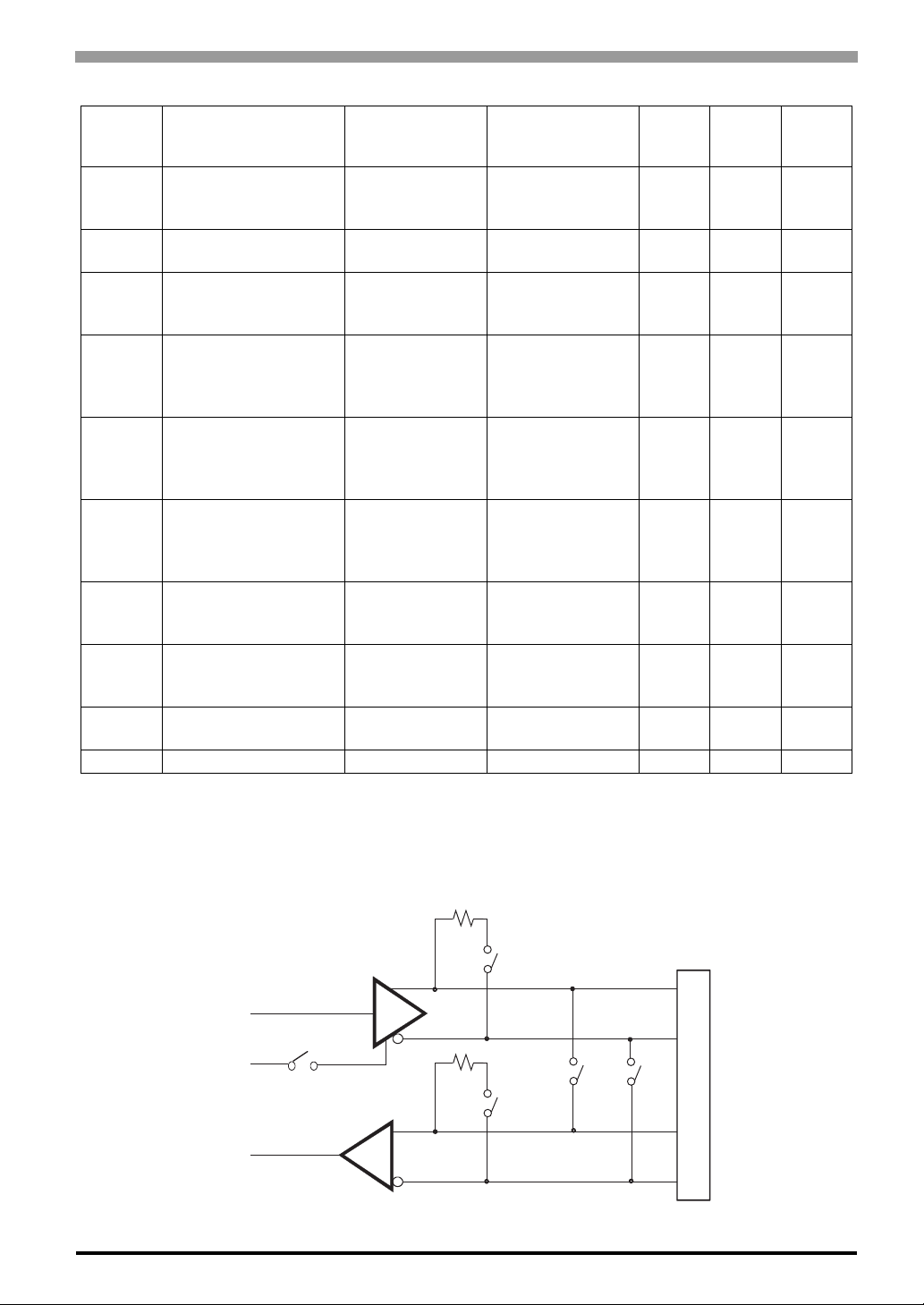
*1 If you use termination resistance, base your settings on your connection specifications.
DIPSW2 (SW4 to SW8) in the above table 2 operate as shown in the circuit diagram below.
SW5
TXA
XD
TS
SW4
SW6
SW7
TXB
SW8
RXA
RXB
COM3
Fig. 1 DIPSW2 (SW4 to SW8) circuit diagram
1-9

Compact Panel Computer PS-3700A (Eden
1.4.2 Printer Interface (LPT1)
This interface conforms to Centronics standards.
D-sub 25 pin (Female)
13
25
Screw Size: (4-40): Inch Type
TM
ESP6000-667MHz Model) User Manual
1
• Electrical Specifications
O.D : Open Drain
T.S : 3 state I/O
TTL : TTL Input
14
Pin
No.
SPP/
ECP
Mode
Signal
Name
EPP
Mode
Signal
Name
Direction
Electrical
Specif.
1 STRB WRITE In/Output O.D/T.S
Pin
No.
*1
SPP/
ECP
Mode
Signal
Name
EPP
Mode
Signal
Name
Direction
Electrical
Specif.
14 AUTOFD DSTRB In/Output O.D/T.S
2 DATA0 DATA0 In/Output O.D 15 ERROR ERROR Input TTL
3 DATA1 DATA1 In/Output O.D 16 INIT INIT In/Output O.D/T.S
4 DATA2 DATA2 In/Output O.D 17 SLCTIN ADSTRB In/Output O.D/T.S
5 DATA3 DATA3 In/Output O.D 18 GND GND
6 DATA4 DATA4 In/Output O.D 19 GND GND
7 DATA5 DATA5 In/Output O.D 20 GND GND
8 DATA6 DATA6 In/Output O.D 21 GND GND
9 DATA7 DATA7 In/Output O.D 22 GND GND
10 ACKNLG ACKNLG Input TTL 23 GND GND
11 BUSY WAIT Input TTL 24 GND GND
12 PE PE Input TTL 25 GND GND
13 SLCT SLCT Input TTL
*1 Pins 1, 14, 16 and 17 will become O.D when the SPP mode specification is used. If the mode
changes to ECP or EPP, these pins will become T.S
*1
*1
*1
1-10

1.5 PS-A Unit External Views and Dimensions
1.5.1 PS-A Unit
383 [15.08]
Top
Chapter 1 Overview
Unit:mm [in]
395 [15.55]
Front
100 [3.94]
5 [0.20]
294 [11.57]
282 [11.10]
Side
1-11

Compact Panel Computer PS-3700A (Eden
TM
ESP6000-667MHz Model) User Manual
1.5.2 External Dimensions (with Installation Fasteners installed)
394.8 [15.54]
160[6.30] 160[6.30]
Top
404.8 [15.94]
5 [0.20]
100 [3.94]
Unit:mm [in]
303.8 [11.96]
165
[6.50]
Front
Bottom
160
[6.30]
Side Rear
Side
293.8 [11.57]
1-12

1.5.3 Panel Cut Dimensions
• Be sure the thickness of the installation panel is from 1.6 mm [0.06 in] to 10 mm
[0.39 in].
• All panel surfaces used should be strengthened. Especially, if high levels of vibration are expected and the PS-A’s installation surface (i.e. an operation panel’s
door, etc.) can move (i.e.open or close) due consideration should be given to the
PS-A’s weight.
Chapter 1 Overview
Unit:mm [in]
l
e
s
s
4
-
t
R
h
a
3
n
[
0
.
1
2
]
+1
383.5 [15.10 ]
0
+0.04
0
0
+1
0
+0.04
282.5
[11.12 ]
• To insure that the PS-A ’ s water resist ance is maintained, be sure to install the PSA into a panel that is flat and free of scratches or dents.
• Be sure all installation tole ra nces are maintained to prevent the unit from falling
out of its installation panel.
1.5.4 Installation Fasteners
Unit:mm [in]
16[0.63]
11[0.43]
16.6[0.65]
M6
Ø10
31[1.22]
[Ø0.39]
1-13

Compact Panel Computer PS-3700A (EdenTMESP6000-667MHz Model) User Manual
Memo
1-14

2 Hardware
Installation
1. Installtion
2. Installing the PS-A Unit
3. Wiring the PS-A
2-1

Compact Panel Computer PS-3700A (Eden
2.1 Installtion
A wide variety of optional units, Main Memory, CF cards, PCMCIA (PC cards) manufactured by Digital
Electronics Corporation and commercial expansion boards (PCI bus compatible board *1), PCMCIA (PC
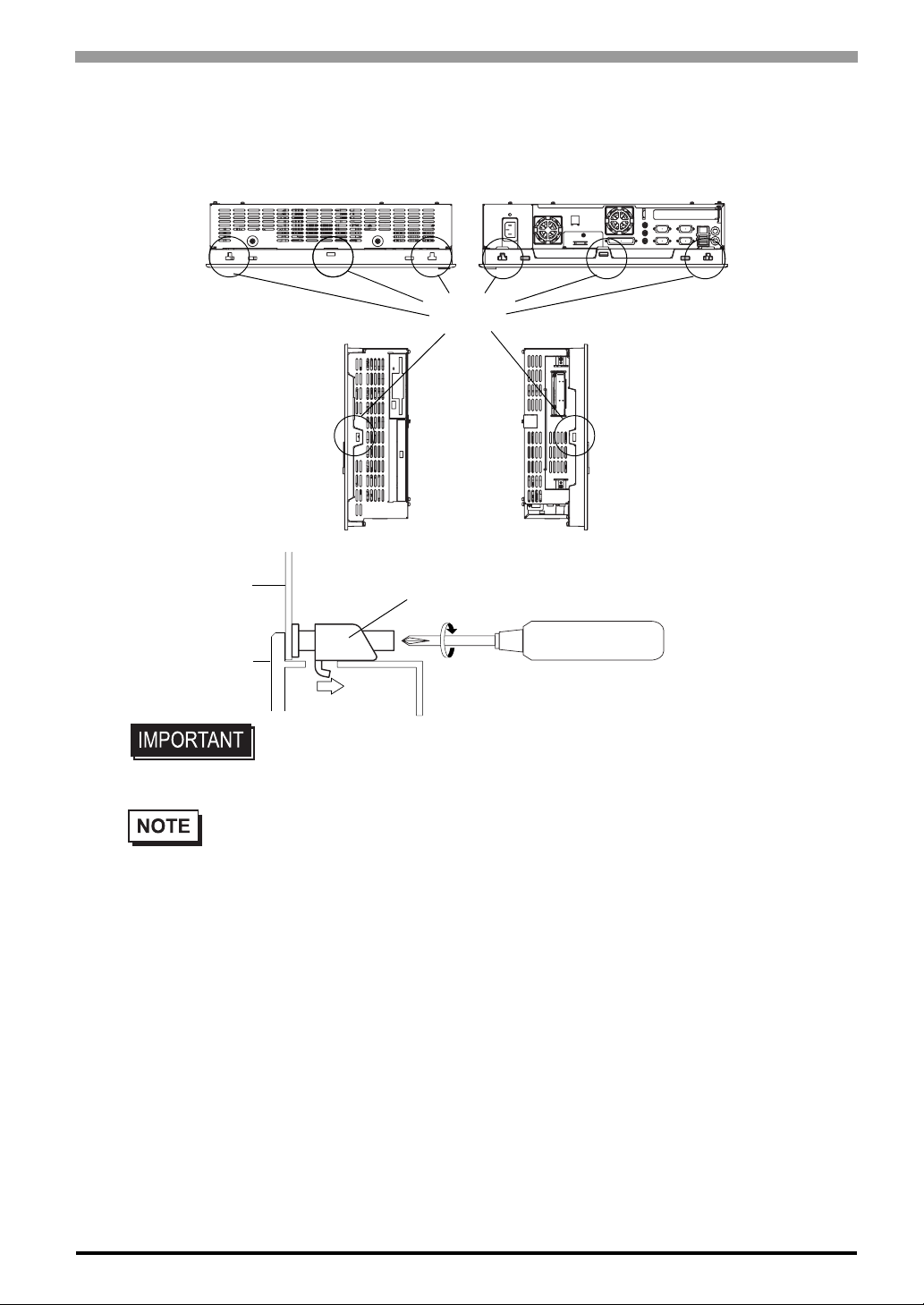
Cards) can be used with the PS-A. Unscrew the five (5) cover attachment screws, and remove the cover.
Install the desired products as shown in the "2.1.2 PS-A Internal View" drawing.
For the detailed optional unit installation procedures, refer to that unit’s "Installation Guide".
Be sure to disconnect the power cord from the power supply and confirm that power is not
supplied to the PS-A unit before installing any optional units, Main Memory, CF cards, or
expansion boards. Failure to do so can result in an electric shock.
• Use a screwdriver to loosen and tighten the screws. Be sure not to tighten the
screws too tightly. Excessive force can damage the equipment.
• When removing or replacing screws, be careful that they do not fall inside the PS-
TM
ESP6000-667MHz Model) User Manual
A unit's chassis.
• When installing the PS-A unit, or when attaching an optional item to the PS-A
unit, do not hold the PS-A unit by its rear-face fan cover while performing the
work. Doing so may damage the fan cover or cause the cover to fall off.
2.1.1 Removing the PS-A Unit's Cover
Lay the PS-A unit on its side and remove the five (5) cover attachment screws. Slide the rear cover up to
remove it in the direction shown. (When reattaching the screws, use a torque of 0.5 to 0.6N•m.)
2-2

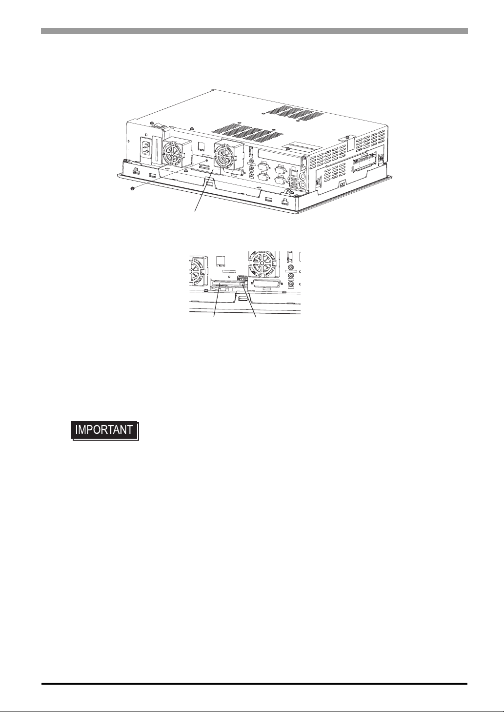
2.1.2 PS-A Internal View
Expansion Board Interface
(1 port)
Chapter 2 Hardware Installation
HDD Unit
CD-ROM Drive
PCMCIA Slot
FDD Drive
(2 ports)
Main Memory Installation
Area (1 port)
2-3

Compact Panel Computer PS-3700A (Eden
M
r
2.1.3 Main Memory Installation
(1) Remove the PS-A unit's rear cover.
TM
ESP6000-667MHz Model) User Manual
SEE
(2) Angle the main memory module down slightly, and push it in until the connector pins mate with the
2.1.1 Removing the PS-A Unit's Cover (page2-2)
module's pins. Then, lower the module until it is horizontal and insert it completely into the connector.
This connector is shown in 2.1.2 PS-A Internal View.
Connector
ain Memory
(3)
(3) Push in the main memory module until the stopper snaps into place.
2.1.4 Expansion Board (PCI) Installation
(1) Remove the PS-A unit’s rear cover.
SEE
(2) Remove the blank panel’s screw, and detach the blank panel.
2.1.1 Removing the PS-A Unit's Cover (page2-2)
(2)
Stoppe
2-4

Chapter 2 Hardware Installation
(3) Insert the expansion board (commercial-type PCI) into the expansion board connector, and secure it in
place using the filler panel’s screw. The necessary torque is 0.5N•m to 0.6N•m.
Expansion Board
Connector
Expansion Board
(Commercial type)
(4) Replace the rear cover and secure it in place using the five (5) attachment screws.
• The maximum size allowed for an expansion board is 240mm [9.44in.] x 106.68mm [4.2in.].
When using an expansion board of this size, be sure to secure it in place using the expansion
board support. Before the rear cover is closed, as explained in step (4) above, remove the expansion board support cover screw and be sure the expansion board support cover is detached. Next,
replace the rear cover, and then secure the expansion board support cover to the rear cover using
the expansion board support cover screw. The necessary torque is 0.5N•m to 0.6N•m.
Expansion Board
Support
2-5

Compact Panel Computer PS-3700A (Eden
2.1.5 PCMCIA Unit Installation
(1) Remove the PCMCIA slot cover’s screws (2).
(2) [Inserting a commercial-type PC Card]
Insert the commercial-type PC Card into the PCMCIA connector.
TM
ESP6000-667MHz Model) User Manual
PCMCIA Slot Cover
Eject Button
PC Card
(commercial)
• The PCMCIA slot has 2 connectors. When inserting the PCMCIA Card, check carefully that it is
connected to the correct connector.
[Removing the PC Card]
Press the eject button twice to remove the PC Card from the PCMCIA connector.
Pressing the eject button once causes its tip to come out.
Pressing the eject button the second ejects the PC Card from the PCMCIA slot.
(3) Replace the PCMCIA slot cover removed in (1) and secure it in place using the two PCMCIA slot
screws. The necessary torque is 0.5N•m to 0.6N•m.
• When using a PC Card with a cable attached, Pro-face recommends you use a clamp or
other type of device to prevent vibration from possibly dislodging the cable.
• Be sure to stop the PS-A unit PC Card's driver prior to removing the PC Card. A failure
to stop this driver may result in damage to either the PC Card, the PC Card's data, or
®
may cause Windows
to hang up. For information on the procedure for stopping the PC
Card's driver, please refer to your OS' User Manual.
2-6
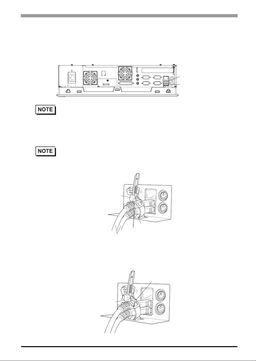
2.1.6 USB Cable Clamp Installation
r
r
This holder prevents the USB cable from becoming disconnected due to vibration, etc.
(1) Place the PS-A unit face-down on a flat surface as shown below. Your PS-A unit has two USB connec-
tors.
• When using only one of the USB ports, be sure to use the lower USB connecto r. This allows you
to securely clamp the USB cable in the cable clamp.
[Attachment]
As shown below, insert the USB Cable Clamp’s band through the Bridge. Pass the USB cables through the
Cable Clamp’s band and securely tighten the clamp band around the cables.
• Be sure the clamp is securely holding the USB cable’s plug and collar.
Chapter 2 Hardware Installation
Upper USB Connecto
Lower USB Connecto
• Be sure the clamp is positioned as shown below, with the clamp pointing upwards - not to the
side. This is to keep the clamp from interfering with nearby connectors and their cables.
Clamp
Bridge
Cable Collars
USB Cables
[Removal]
To remove the clamp from the USB cables, push down on the clamp strap’s clip to release it while pulling up
on the clamp.
Strap Clip
Clamp
2-7

Compact Panel Computer PS-3700A (Eden
TM
ESP6000-667MHz Model) User Manual
2.1.7 CF Card Installation and Removal
When using the PS-A Unit and a CF Card, follow the precautions below:
Be sure to use only CF Cards manufactured by the Digital Electronics Corporation. PS-A
unit performance cannot be guaranteed when using another manufacturer's CF Card.
Be sure to follow the instructions given below to prevent the CF Card's internal data from
being destroyed or a CF Card malfunction from occurring:
• DO NOT bend the CF Card.
• DO NOT drop or strike the CF Card against another object.
• Keep the CF Card dry.
• DO NOT touch the CF Card connectors.
• DO NOT disassemble or modify the CF Card.
When using the CF Card Unit and the CF Card
Prior to inserting the CF Card, be sure to confirm that the rear and the front of the CF Card
are correctly oriented, and that the CF Card connector position is correct. If the CF Card is
inserted incorrectly, the CF Card, its internal data, and the CF card unit may be damaged.
Since the PS-A unit's OS views the CF Card as a hard disk, do not remove or insert the CF
Card when the unit's power is switched ON. Doing so may damage data and stop OS operation. Be sure to shut down the OS and switch power OFF prior to removing or inserting a
CF Card.
Never turn OFF or reset the PS-A while accessing the CF Card to prevent damaging file
data. Also, be sure to shut down the PS-A unit's OS before turning OFF the main power.
Data Overwrite Limit
The CF Card has a data overwrite limit of approximately 100,000 times. Therefore, be sure to back up all CF
Card data regularly to another storage media. (100,000 times assumes the overwriting of 500KB of data in
DOS format)
A CF Card Insertion and Removal
Familiarize yourself with the differences between the top and bottom surfaces of the CF Card. Also, be sure to
2-8
read the CF Card's installation guide to ensure that the Card is properly oriented when it is inserted (i.e.
whether the top of the card is up or down etc.)
Chapter 2 Hardware Installation
When inserting the CF Card
(1) Unscrew the CF Card cover's attachment screw (1), and remove the CF Card cover.
CF Card Cover
(2) Insert the CF Card firmly into the CF card slot, and check that the eject button pops out.
CF Card Eject Button
Removing the CF Card
(3) Press the eject button in fully to remove the CF Card from the CF Card slot.
(4) After inserting/removing the CF card, be sure to replace the CF Card cover and secure it in place using
the attachment screw.
• The necessary torque is 0.5N•m to 0.6N•m.
2-9
Compact Panel Computer PS-3700A (Eden
2.2 Installing the PS-A Unit
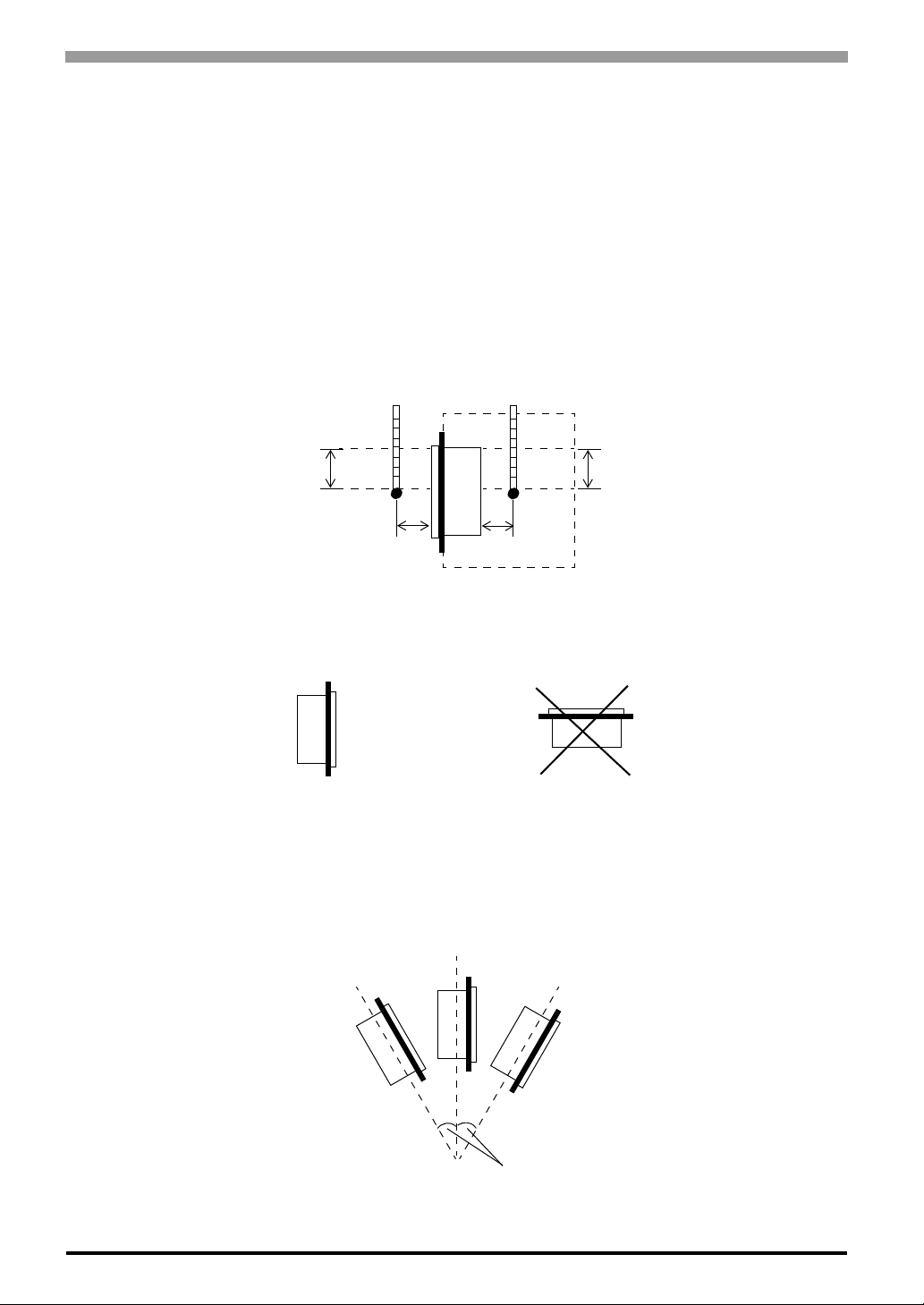
2.2.1 Installation Caution Temperature Related Cautions
• T he PS-A should be installed in a ve rtical position, and forced air cooling should be used, instead of natural air circulation.
• Check the ambient temperature at the positions shown in the illustrations below. Temperatures exceeding
the proper ambient temperature (When using HDD: 5 to 50°C, When not using HDD: 0 to 50°C) may lead
to product breakdown.
Panel Face Panel Interior
TM
ESP6000-667MHz Model) User Manual
100 mm
30 mm
30 mm
100 mm
Installation Positioning Cautions
Be sure to install the panel in an upright (vertical) position.
OK
Vertical
Also, be sure that the panel’s viewing angle is tilted no more than 30 degrees from parallel to the operator (i.e.
directly in front).
Horizontal
2-10
No more than 30 degrees of tilt

Chapter 2 Hardware Installation
Installation Location
• A void placing the PS-A next to other devices that might cause overheating.
• Keep the PS-A away from arc-generating devices such as magnetic switches and non-fuse breakers.
• Avoid using the PS-A in environments where corrosive gases are present.
• To ensure the reli ability, operabil ity and ventilation of the PS-A, be sure to install it in locations that are
more than 50mm away from adjacent structures or equipment. Also, consider the need for installing or
removing expansion boards, or connectors when designing and installing your PS-A.
Side View
50 mm
50 mm
50 mm
50 mm
Rear View
50 mm
50 mm
50 mm
Vibration and Shocks
If the PS-A is moved when its enclosure doors are open, or while it is installed in a rack equipped with caster
wheels, or when using a stand with an arm attached or when attached to a wall, the hard disk can rece ive
excessive vibration or jolting. Be especially careful at this time.
PS-A Unit
When using the HDD Up to 4.9m/s
When not using the HDD Up to 9.8m/s
Shock
Resistance
2
2
• Be sure not to move the PS-A unit while the HDD is starting up. This can lead to a
machine breakdown (Even a slight movement of the PS-A should not be performed).
• When using a fan to cool the PS-A unit, be sure that the fan does not point
directly at any of the PS-A’s disk drive units.
2-11

Compact Panel Computer PS-3700A (Eden
G
m
2.2.2 Installation Procedures
Follow the steps given below when installing the PS-A.
Attaching the Installation Gasket
Even if the your PS-A’s Installation Gasket is not needed to prevent water from entering the unit, the gasket
also acts as a vibration absorber and should always be attached. To install it, place the PS-A face down on a
soft surface and attach the gasket to the rear side of the display face, in the bezel’s groove (see picture below).
• Before mounting the PS-A into a cabinet or panel, check that the installation gasket is attached to the unit.
• A gasket which has been used for a long period of time may be scratched or dirty,
and may have lost much of its water resistance. Be sure to change the gasket at
least once a year, or when scratches or dirt become visible.
• The corresponding gasket is CA3-WPG15-01.
• Since the gasket is flexible but not elastic, be careful not to stretch it unnecessar-
TM
ESP6000-667MHz Model) User Manual
ily, as doing so could tear the gasket.
• Be sure, when pushing the gasket into the installation groove and around the corners of the PS-A, that the gasket’s seam is not placed in a corner. Placing the
seam here could eventually cause the gasket to tear
• Be sure to place the gasket’s flat, non-grooved side facing down.
PS-A Rear Face
Gasket
Installation
Groove
asket sea
• If the installation gasket is not properly inserted into the groove, the gasket’s
moisture resistance may not be equivalent to IP65f.
• When the installation gasket is properly inserted, approximately 2.0 mm of it will
extend outside the groove. Before installing a PS-A into a panel, be sure to confirm that the gasket is correctly in place.
2-12

Chapter 2 Hardware Installation
Create a Panel Cut
Create a panel cut for the PS-A, like that pictured here. Two additional items, the installation gasket and the
installation fasteners are required when installing the PS-A.
SEE
1.5.3 Panel Cut Dimensions (page1-13)
Panel
Panel Cut
• To obtain the maximum degree of moisture resistance, be sure to install the PS-A on a smooth,
flat surface.
• The panel itself can be from 1.6 mm [0.06 in] to 10.0 mm [0.39 in] thick
• Strengthening may be required for the panel. Be sure to consider the weight of
the PS-A when designing the panel.
1.6 mm [0.06 in] - 10.0mm [0.39 in]
PS-A Viewing Angle
• Be sure that the panel’s viewing angle is tilted no more than 30 degrees from parallel to the operator (i.e.
operator is directly in front).
OK
OK
• A void placing the PS-A next to other devices that might cause overheating.
• A void using the PS-A where the ambient temperature will be higher than the allowed specification.
• Keep the PS-A away from arc-generating devices such as magnetic switches and non-fuse breakers.
• Avoid using the PS-A in environments where corrosive gases are present.
OK
Must be 30 degrees or less
2-13

Compact Panel Computer PS-3700A (Eden
Insert the PS-A into the installation slot
383.5
[15.10 ]
PS-A
• Be sure the panel cut’s actual measurements are the same as those given here,
otherwise the PS-A may slip or fall out of the panel.
TM
ESP6000-667MHz Model) User Manual
+1
0
+0.04
0
4
n
u
]
2
r
1
e
.
d
0
[
3
R
-
0
+1
+0.04
Side panel
0
282.5
[11.12 ]
Unit:mm [in]
Mounting panel
2-14
Chapter 2 Hardware Installation
Attach and Secure the Rear Installation Fasteners
(1) Locate the PS-A’s attachment holes, located on the top, bottom, and sides of the PS-A.
Top
Attachment
Holes
Right Side
Bottom
Left Side
Panel
PS-A
• Excessive torque may damage the PS-A unit.
• To ensure a high degree of moisture resistance, the torque should be 0.5N•m.
• Depending on the installation panel's thickness, etc., the number of installation fasteners used
may need to be increased to provide the desired level of moisture resistance.
• The corresponding installation fasteners are CA3-ATFALL-01.
Installation Fastener
2-15
Compact Panel Computer PS-3700A (Eden
2.3 Wiring the PS-A
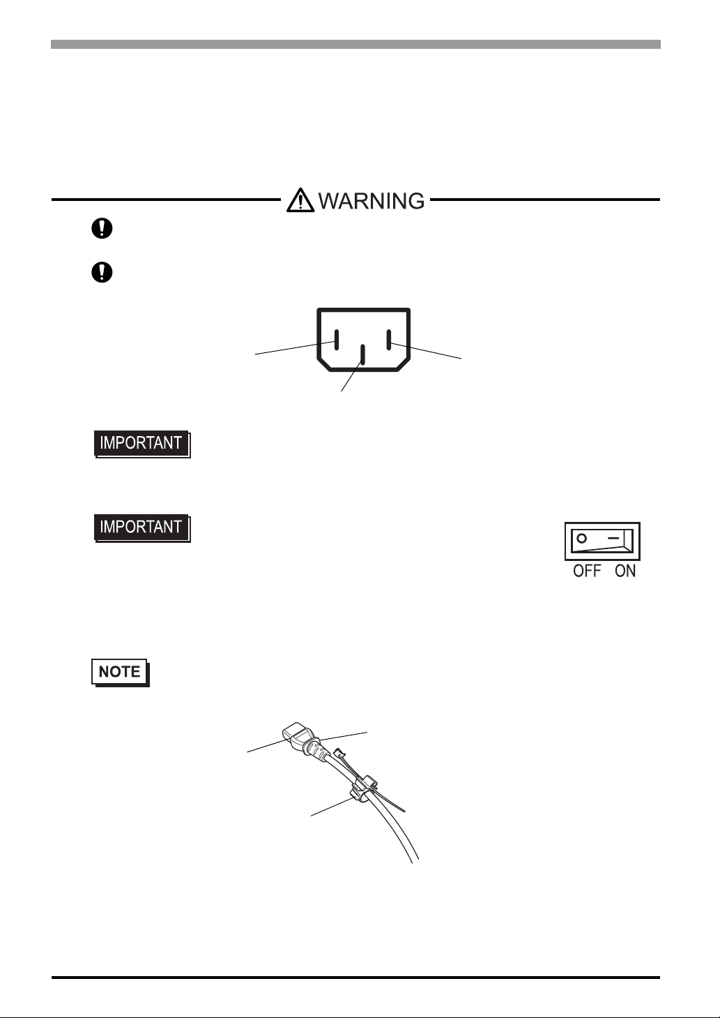
2.3.1 Connecting the Power Cord
Insert the power cord (AC inlet plug) into the PS-A's bottom face AC connector.
To avoid an electric shock, check that the PS-A's power supply is turned OFF, via a
breaker, or similar unit before connecting the PS-A's power cord to the AC connector.
To avoid the dangers of fire, electric hazards and equipment damage, be sure to use only
the specified voltage when operating the PS-A.
TM
ESP6000-667MHz Model) User Manual
N
FG
• The Power Cord included in the PS-A unit's package is designed only for
AC100V or AC115V use. Any other voltage will require a different cord.
AC Connector *
L
1
Installing the AC Power Cord Clamp
• Be sure to connect the power cord only after confirming that
the PS-A unit rear face power switch is turned OFF.
Attaching the AC Power Cord
(1) Open the AC Power Cord Clamp and insert the AC Power Cord as shown in fig. 1. Then, close the Cord
Clamp until it clicks into place and locks around the AC Power Cord Collar..
• The Cord Clamp has four teeth for locking. These are to adjust the amount of grip used to hold
the AC Power Cord Collar.
AC Plug Collar
AC Plug
2-16
Cord Clamp
Figure 1
*1 L : AC Input Terminal-live line
N : AC Input Terminal-neutral lin e
FG : Ground Terminal connected to the PS-A chassis
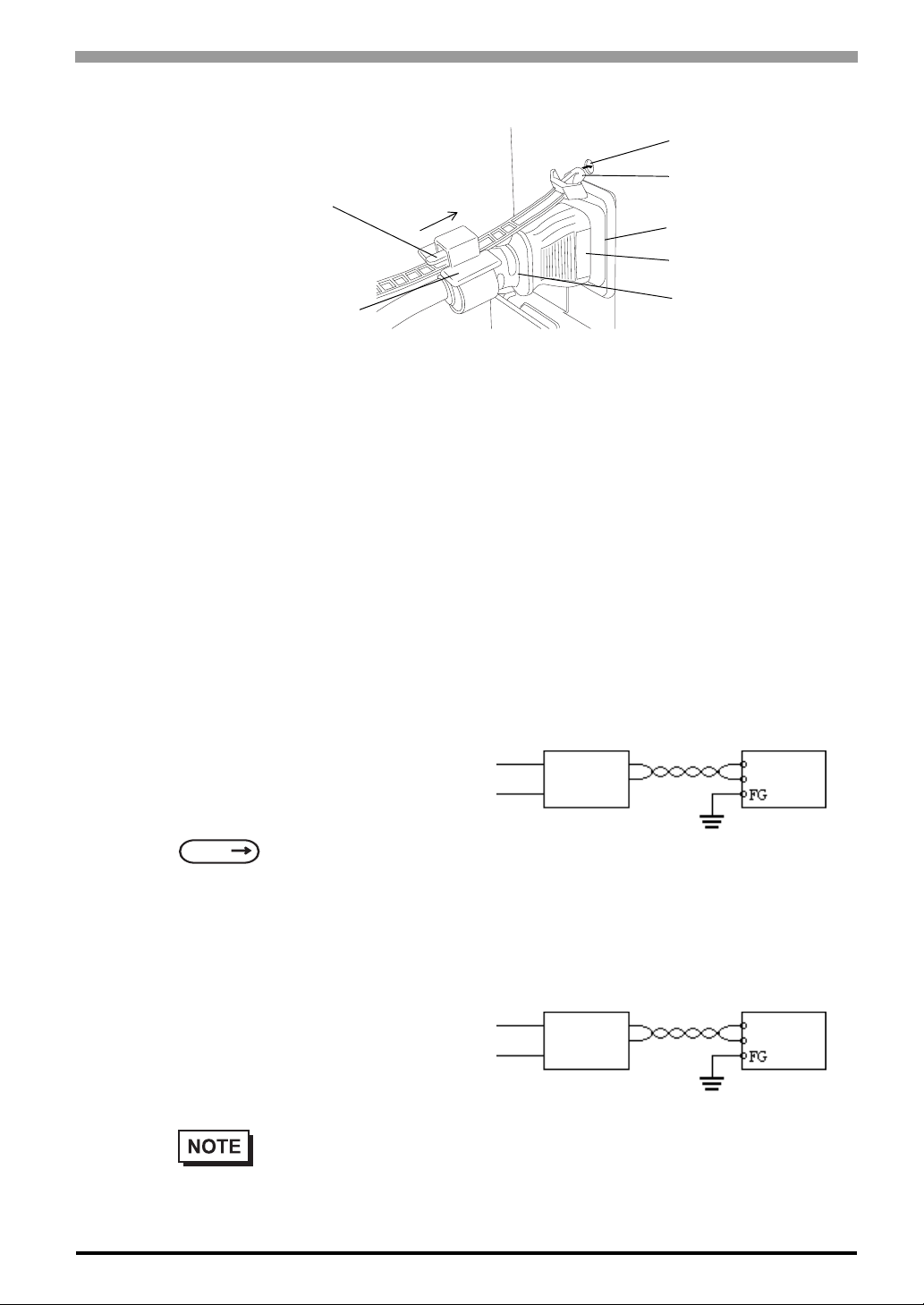
(2) Connect the AC plug to the PS-A’s AC connector, as shown in fig. 2.
(3)
Lock Tab Release
(4)
Chapter 2 Hardware Installation
Lock Pin Hole
Cord Clamp Lock Pin
AC Connector
AC Plug
Cord Clamp
(3) Insert the Cord Clamp Lock Pin into the PS-A’s Lock Pin Hole.
(4) Adjust the Lock Pin’s Lock Tab length until it is securely held.
Removing the AC Power Cord
(1) While lifting up on the Lock Pin’s Lock Tab Release, pull the AC Plug, Plug Collar and Cord Clamp
backwards to disconnect it from the PS-A.
(2) Open the Cord Clamp and remove the AC Power Cord from the Cord Clamp.
2.3.2 Power Supply Cautions
When connecting the PS-A unit’s AC connector, please be aware of the following:
• If voltage fluctuations are expected to vary
beyond the specified range, connect a constant voltage transformer.
Figure 2
(2)
Constant
Constant
voltage
voltage
transformer
transformer
AC Plug Collar
Twisted-pair
Twisted-pair
cord
cord
PS-A
PS-A
SEE
For information about the
specified voltage, refer to
7.1 General Specifications
(page7-2)
• Use a low-noise power supply both between
the lines and between the PS-A and its
ground. If there is still excess noise, connect
an insulating transformer (noise-prevention
type).
• Be sure any constant or insulating transformer used has a
capacity of 200VA or more.
Insulting
transformer
Twisted-pair
cord
PS-A
2-17

Compact Panel Computer PS-3700A (Eden
TM
ESP6000-667MHz Model) User Manual
• Wire the power cords of the PS-A, I/O
devices, and power supply devices separately.
• To improve noise immunity, it is recommended to attach a ferrite core to the power
cord.
• Isolate the main circuit (high voltage, large
current) line, I/O signal lines, and power
cord, and do not bind or group them
together.
Main power
Main power
source
source
AC200V
AC200V
AC100V
Main
power
source
PS-A
PS-A
power source
power source
I/O
I/O
power
power
source
source
Main circuit
Main circuit
power source
power source
PS-A
power
source
I/O
power
source
PS-A
I/O
device
PS-A
PS-A
I/O
I/O
device
device
I/O
I/O
device
device
Power
Power
device
device
• To prevent damag e from lightning, connect
a lightning surge absorber.
• Ground the lightning surge
absorber (E1) and the PS-A
(E2) separately.
• Select a lightning surge
absorber which will not exceed
the allowable circuit voltage,
even when the voltage rises to
the maximum.
AC
Twisted-pair
cord
E1
PS-A
FG
E2
Lightning surge absorber
2-18
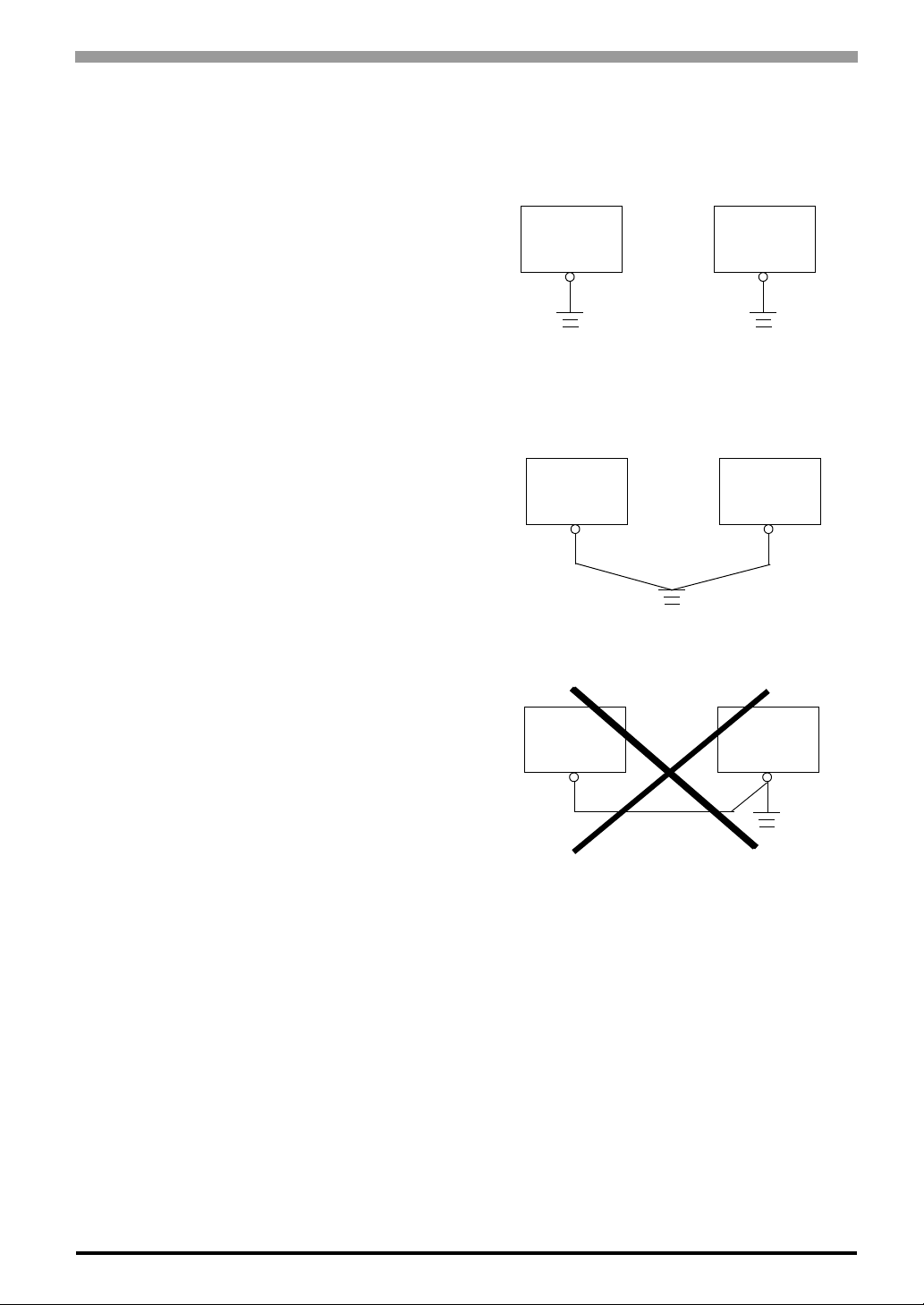
2.3.3 Grounding Cautions
(a) Dedicated Ground *1
• Set up a dedicated ground when using the
rear panel’s FG terminal.
(b) Shared Ground - allowed *1
• If a dedicated ground is not possible, use a
shared ground, as shown in figure.
• Inside the PS-A unit, the SG (Signal
Ground) and FG (Frame Ground) terminals
are connected to each other.
PS-A
PS-A
Chapter 2 Hardware Installation
Other device
Other device
(c) Shared ground - not allowed
• When connecting an external device to PSA with the SG terminal, ensure that no
short-circuit loop is created when you set
up the system.
• The grounding point must be as close to
the PS-A as possible, and the grounding
wires must be as short as possible. If the
wires must be long, use thick, insulated
wires and run them through conduits.
2.3.4 Cautions When Connecting I/O Signal Lines
• I/O signal lines must be wired separately from the power circuit cable. If the power circuit cable needs to
be wired together with the input/output (I/O) signal lines for any reason, use shielded cables and ground
one end of the shield to the PS-A’s FG terminal.
• To improve noise immunity, it is recommended to attach a ferrite core to the power cord.
PS-A
Other device
*1 Use a grounding resistance of 100Ω or less, and a 2 mm
standard. For details, contact your local PS-A distributor.
2
or thicker wire, or your country’s applicable
2-19

Compact Panel Computer PS-3700A (Eden
Memo
TM
ESP6000-667MHz Model) User Manual
2-20

3 System Setup
1. Setup Procedures
2. System Parameters
3-1
Compact Panel Computer PS-3700A (Eden
3.1 Setup Procedures
• Normally, use only the factory (default) settings.
• The following settings are those pre-set at the factory.
(1) Connect a keyboard to the PS-A.
(2) Turn the PS-A’s power ON.
(3) After the message "Press <DEL> to Enter SETUP" appears, press the [DEL] key until the following
screen appears.
Phoenix AwardBIOS CMOS Setup Utility
TM
ESP6000-667MHz Model) User Manual
4Standard CMOS Features
4Advanced BIOS Features
4Advanced Chipset Features
4Integrated Peripherals
4Power Management Setup
4PnP/PCI Configurations
4System Monitor Setup
ESC : Quit F9 : Menu in BIOS
F10 : Save & Exit Setup
Time, Date, Hard Disk Type...
KEYBOARD ACTION KEYS
Provides a summary of the keyboard keys used to carry out the set up.
SYSTEM SETTING SELECTION AREA
Each of the titles (areas) listed here contains system setting items.
4 Frequency/Voltage Control
Load Fail-Safe Defaults
Load Optimized Defaults
Set Supervisor Password
Set User Password
Save & Exit Setup
Exit Without Saving
↑↓→←: Select Item
3-2
(4) Use the arrow keys to move the cursor to the desired selection.

3.2 System Parameters
3.2.1 Standard CMOS Features
• Normally, use only the factory (default) settings.
Selecting the STANDARD CMOS FEATURES menu item produces the following screen.
Phoenix AwardBIOS CMOS Setup Utility
Date (mm:dd:yy): Wed,Jun 25 2003
Time (hh:mm:ss): 14 : 50 : 3
4IDE Primary Master [None]
4IDE Primary Slave [None]
4IDE Secondary Master [None]
4IDE Secondary Slave [None]
Drive A [1.44M, 3.5 in.]
Video [EGA/VGA]
Halt On [All,But Keyboard]
Base Memory 640K
Extended Memory 11366K
Total Memory 114688K
Chapter 3 System Setup
Standard CMOS Features
Item Help
Menu Level 4
Change the day, month, year
and century
↑↓→←: Move Enter: Select +/-/PU/PD: Value F10: Save ESC: Exit F1: General Help
F5: Previous Values F6: Fail-Safe Defaults F7: Optimized Defaults
Date (mm:dd:yy)
The PS-A unit’s internal calendar and clock allow you to set the date. The day of the week is automatically
set.
Month: Jan/Feb/Mar/Apr/May/Jun/Jul/Aug/Sep/Oct/Nov/Dec
Day:1 to 31
Year: 1999 to 2099
Time (hh:mm:ss)
The PS-A unit’s internal cl ock can be set.The hh/mm/ss (0:0:0) format is factory set prior to shipping.
Hours: 0 to 23
Minutes: 0 to 59
Seconds: 0 to 59
3-3

Compact Panel Computer PS-3700A (Eden
IDE Primary (Secondary) Master (Slave)
Displays the name of the IDE type Hard Disk connected to the PS-A. Pressing the [Enter] key will call up the
Parameter settings menu. For details,
TM
ESP6000-667MHz Model) User Manual
SEE
3.2.2 IDE HDD Auto-Detection (page3-5)
Drive A
This setting determines the format used by the PS-A’s internal floppy disk drive. The available settings are
[None], [360K - 5.25in], [720K - 3.5in], [1.2M - 5.25in], [1.44M - 3.5in], or [2.88M, 3.5in].
The factory setting is [1.44M - 3.5in], and recommended for most users.
Video
The selections for the screen (video) mode. The available settings are [EGA/VGA], [CGA40], [CGA80] and
[MONO]. The [EGA/VGA] selection is factory set and recommended for most users.
Halt On
Designates the type of processing that will be performed when an error occurs during the Initial Start-Up’s
Self Test. The [All But Keyboard] selection is factory set and recommended for most users.
[All Errors] : Displays all errors and stops the unit.
[No Errors] : Displays all errors and does not stop the unit.
[All,But Keyboard] : Displays all errors, except for those related to the keyboard, and stops the unit.
[All,But Diskette] : Displays all errors, except for those related to the disk drive (FDD), and stops the
unit.
[All,But Disk/Key] : Displays all errors, except for those related to the disk drive (FDD) and key-
board, and then stops the unit.
3-4

3.2.2 IDE HDD Auto-Detection
Selecting either [IDE Primary (Secondary) Master] or [IDE Primary (Secondary) Slave] will call up the following menu. The following example uses the [IDE Primary Master] setting.
Phoenix AwardBIOS CMOS Setup Utility
IDE HDD Auto-Detection [Press Enter]
IDE Primary Master [Auto]
Access Mode [Auto]
Capacity
Cylinder
Head
Precomp
Landing Zone
Sector
Chapter 3 System Setup
IDE Primary Master
Item Help
Menu Level 44
T o auto-detect the HDD’s size,
head... on this channel
↑↓→←: Move Enter: Select +/-/PU/PD: Value F10: Save ESC: Exit F1: General Help
F5: Previous Values F6: Fail-Safe Defaults F7: Optimized Defaults
IDE HDD Auto-Detection
This setting detects the hard disk connected to the IDE interface.
IDE Primary (Secondary) Master (Slave)
This setting designates the IDE type Hard Disk’s parameter setting method. The available settings are [None],
[Auto], or [Manual]. The factory default setting is [Auto] and is recommended for most users.
Access Mode
This setting designates the IDE type Hard Disk’s access mode. The available settings are [CHS], [LBA],
[Large], or [Auto]. The factory default setting is [Auto] and is recommended for most users.
Capacity/Cylinder/Head/Precomp/Landing Zone/Sector
These settings designate individual IDE-type Hard Disk parameter settings. When the [IDE Primary (Secondary) Master (Slave)] setting is set to [Manual], the Access Mode must be [CHS]. When the [IDE Primary
(Secondary) Master (Slave)] setting is set to [Auto], these values are automatically detected. [Capacity] is set
automatically.
3-5

Compact Panel Computer PS-3700A (Eden
3.2.3 Advanced BIOS Features
Selecting the ADVANCED BIOS FEATURES menu item calls up the following screen.
Phoenix AwardBIOS CMOS Setup Utility
Virus Warning [Disabled]
CPU Internal Cache [Enabled]
External Cache [Enabled]
CPU L2 Cache ECC Checking [Enabled]
Quick Power On Self Test [Enabled]
First Boot Device [Floppy]
Second Boot Device [HDD-0]
Third Boot Device [CDROM]
Boot Other Device [Disabled]
Boot Up Floppy Seek [Enabled]
Boot Up NumLock Status [On]
Gate A20 Option [Fast]
Typematic Rate Setting [Disabled]
x Typematic Rate(Chars/Sec) [6]
x Typematic Delay (Msec) [250]
Security Option [Setup]
OS Select For DRAM > 64MB [Non-OS2]
Video Shadow [Enabled]
C8000-CBFFF Shadow [Disabled]
CC000-CFFFF Shadow [Disabled]
D0000-D3FFF Shadow [Disabled]
D4000-D7FFF Shadow [Disabled]
D8000-DBFFF Shadow [Disabled]
DC000-DFFFF Shadow [Disabled]
Small Logo (EPA) Show [Disabled]
↑↓→←: Move Enter: Select +/-/PU/PD: Value F10: Save ESC: Exit F1: General Help
F5: Previous Values F6: Fail-Safe Defaults F7: Optimized Defaults
TM
ESP6000-667MHz Model) User Manual
Advanced BIOS Features
Menu Level 4
Allows you to choose
the VIRUS warning
feature for IDE Hard
Disk boot sector
protection. If this
function is enabled
and someone attempts to
write data into this
area, BIOS will show a
warning message on
screen and alarm will beep
Item Help
Virus Warning
This setting determines whether to display a warning when a write to the HDD’s start-up sector is attempted.
The available settings are [Enabled] or [Disabled] . The factory default setting is [Disabled] and is recommended for most users.
CPU Internal Cache
Designates if CPU L1 Cache Memory usage is enabled or disabled. Selections are [Disabled] and [Enabled].
The factory setting is [Enabled].
External Cache
Designates if CPU L2 Cache Memory usage is enabled or disabled. Selections are [Disabled] and [Enabled].
The factory setting is [Enabled].
CPU L2 Cache ECC Checking
Designates if CPU L2 Cache Memory’s ECC check is to be performed or not. Selections are [Disabled] and
[Enabled]. The factory setting is [Enabled].
3-6

Chapter 3 System Setup
Quick Power On Self Test
This setting determines whether the quick self test is performed when the power is turned on. The avail abl e
settings are [Disabled] or [Enabled]. The factory default setting is [Enabled] and is recommended for most
users.
First/ Second/ Third Boot Device
The selections for the search drive sequence of the operating system. The available settings are [Floppy],
[HDD-0], [SCSI], [CDROM], [HDD-1], [HDD-2], [HDD-3], [USB-FDD], [USB-ZIP], [USB-CDROM],
[USB-HDD], [LAN], and [Disabled]. Factory settings are: First: [Floppy], Second: [HDD-0], Third:
[CDROM].
Boot Other Device
Designates if a device other than the device designated in the First/Second/Third Boot Device setting will be
used for startup. The available settings are [Disabled] or [Enabled]. The factory defa ult sett ing is [Disabled].
Boot Up Floppy Seek
The setting checks whether the floppy disk drive is installed during the system boot-up process.
The available settings are [Disabled] or [Enabled]. The factory default setting is [Enabled] and is recommended for most users.
Boot Up NumLock Status
This setting specifies the NumLock key status upon the startup. The available settings are [On] and [Off]. The
factory default setting is [On] and is recommended for most users.
Gate A20 Option
Designates the access speed used when accessing 1MB or more of memory. Select [Fast] (Enables fast memory access - allows chipset to handle Gate A20) or [Normal] (Standard method - W indows compatible PC uses
the keyboard controller for access). The factory setting is [Fast].
Typematic Rate Setting
The setting specifies the keyboard speed used when repeating characters. The a vaila ble sett ings are [E nabled]
and [Disabled]. The factory default setting is [Disabled] and is recommended for most users.
Typematic Rate (Chars/Sec)
This setting specifies the actual typematic rate (repeated character input per second) when the [Typematic
Rate Setting] option is set to [Enabled]. The set tings are used to determine how many repeats are performed in
one second. The factory default setting is [6] and is recommended for most users.
3-7
Compact Panel Computer PS-3700A (Eden
Typematic Delay (Msec)
When [Typematic Rate Setting] is set to [Enabled], this setting determines the delay period unti l the initial
repetition is started. The [250] selection is factory set and is recommended for most users.
Security Option
This setting designates the area to request a password. If a password needs to be entered, sele ct [Setup] in
BIOS setup, or [System] during system startup. This setting is NOT available if the password is not set in the
[SET SUPER VISOR PASSWORD] or [SET USER PASSWORD] areas. The factory default setting is [Setup]
and is recommended for most users.
[SET SUPERVISOR PASSWORD]
TM
ESP6000-667MHz Model) User Manual
SEE
[SET USER P ASSWORD]
SEE
3.2.13 Set Supervisor Password (page3-23)
3.2.14 Set User Password (page3-23)
OS Select For DRAM > 64MB
The available settings are [Non-OS2] and [OS2]. The factory default setting is [Non-OS2] and is recommended for most users.
Video BIOS Shadow
Designates if VIDEO BIOS's BIOS is copied from ROM to RAM. The factory setting is [Enabled].
Small Logo (EPA) Show
Enables/disables the initial display at startup of the EP A logo. The available selections are [E nabled] and [Disabled], [Disabled] is factory set and recommended for most users.
3-8
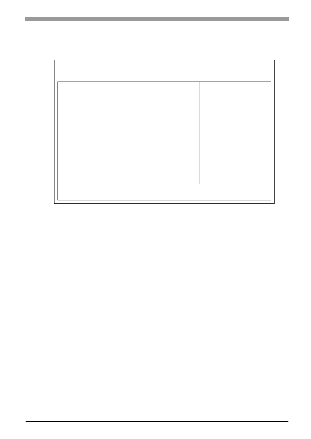
3.2.4 Advanced Chipset Features
Selecting the ADVANCED CHIPSET FEATURES menu item calls up the following screen.
Phoenix AwardBIOS CMOS Setup Utility
DRAM Timing by SPD [Enabled]
Memory Hole [Disabled]
P2C/C2P Concurrency [Enabled]
System BIOS Cacheable [Disabled]
Video BIOS Cacheable [Disabled]
Frame Buffer Size [16M]
AGP-4X Mode [Enabled]
AGP Graphics Aperture Size [64MB]
AGP Driving Control [Auto]
OnChip USB [Enabled]
USB Keyboard Support [Enabled]
OnChip Sound [Auto]
CPU to PCI Write Buffer [Enabled]
PCI Dynamic Bursting [Enabled]
PCI Master O WS Write [Enabled]
PCI Delay Transaction [Disabled]
PCI #2 Access #1 Retry [Disabled]
AGP Master 1 WS Write [ Disabled]
AGP Master 1 WS Read [Disabled]
Chapter 3 System Setup
Advanced Chipest Features
Item Help
Menu Level 4
↑↓→←: Move Enter: Select +/-/PU/PD: Value F10: Save ESC: Exit F1: General Help
F5: Previous Values F6: Fail-Safe Defaults F7: Optimized Defaults
DRAM Timing by SPD
Designates the DRAM Timing settings manually or automatically (SPD: Serial Presence Detect).
Settings available are [Enabled (automatically)] and [Disabled (manually)], the factory default setting is
[Enabled] and strongly recommended for most users.
Memory Hole
Reserves memory area for the ISA card and improves performance.
A vailable selections are [Enabled] and [Disabled]. The factory setting is [Disabled].
P2C/C2P Concurrency
Allows simultaneous transfer of data from a PCI card to the CPU a nd from the CPU to the PCI c ard. Available
selections are [Enabled] and [Disabled]. The factory setting is [Enabled].
System BIOS Cacheable
Sets whether the System BIOS Cache is used or not. When the OS is set to use this cache, the PS-A unit’s processing speed will increase. Settings available are [Enabled] and [Disabled]. The factory setting is [Disabled]
and is recommended for most users.
3-9

Compact Panel Computer PS-3700A (Eden
Video BIOS Cacheable
Sets whether the Video BIOS Cache is used or not. Settings available are [Enabled] and [Disabled]. The factory setting is [Disabled]. When this feature is [Enabled], the BIOS ROM range available for caching is from
C0000h - F7FFFh, which will improve video performance. However, if another program tries to write to this
area of memory, a system error may occur.
AGP-4X Mode
This feature enables/disables the AGP-4X Mode feature.
The available selections are [Enabled] and [Disabled]. The factory setting is [Enabled].
AGP Graphics Aperture Size
Designates the address range used for PCI memory addresses allocated to AGP graphic memory. The available settings are [4MB], [8MB], [16MB], [32MB], [64MB], [128MB] or [256MB]. [64MB] is the factory setting.
TM
ESP6000-667MHz Model) User Manual
AGP Driving Control
Designates if AGP Drive Control is used.
Available selections are [Auto] and [Manual]. The factory setting is [Auto].
OnChip USB
Designates if the Onchip USB is used.
A v a ilable selections are [Enabled] and [Disabled]. The factory setting is [Enabled].
USB Keyboard Support
Designates if the USB Keyboard is used.
A v a ilable selections are [Enabled] and [Disabled]. The factory setting is [Enabled].
OnChip Sound
Designates if the Onchip Sound is used.
Available selections are [Auto] and [Disabled]. The factory setting is [Auto].
CPU to PCI Write Buffer
Designates if the Write Buffer between the CPU and the PCI board is to be enabled or not.
A v a ilable selections are [Enabled] and [Disabled]. The factory setting is [Enabled].
PCI Dynamic Bursting
Selecting [Enabled] temporarily saves data to the PCI W rite Buffe r . Selecting [Disabled] sends data dire ctly to
the PCI bus. Available selections are [Enabled] and [Disabled]. The factory setting is [Enabled].
3-10

Chapter 3 System Setup
PCI Master O WS Write
Designates the wait time used when writing data to the PCI board.
Available selections are [Enabled] and [Disabled]. Selecting [Enabled] means there is no wait time.
The factory setting is [Enabled].
PCI Delay Transaction
Controls the transaction delay function.
A vailable selections are [Enabled] and [Disabled]. The factory setting is [Disabled].
PCI #2 Access #1 Retry
During AGP (PCI #2) Master Retry, designates if the AGP is to be disconnected or not.
A vailable selections are [Enabled] and [Disabled]. The factory setting is [Disabled].
AGP Master 1 WS Write
Designates the wait time used when writing data to the AGP.
Available selections are [Enabled] and [Disabled]. Selecting [Enabled] means there is no wait time. The factory setting is [Disabled].
AGP Master 1 WS Read
Designates the wait time used when reading data from the AGP.
Available selections are [Enabled] and [Disabled]. Selecting [Enabled] means there is no wait time. The factory setting is [Disabled].
3-11

Compact Panel Computer PS-3700A (Eden
3.2.5 Integrated Peripherals
Selecting INTEGRATED PERIPHERALS SETUP menu item Displays the foll owing screen.
Phoenix AwardBIOS CMOS Setup Utility
OnChip IDE Channel 0 [Enabled]
OnChip IDE Channel 1 [Enabled]
IDE Prefetch Mode [Enabled]
Primary Master PIO [Auto]
Primary Slave PIO [Auto]
Secondary Master PIO [Auto]
Secondary Slave PIO [Auto]
IDE Primary Master UDMA [Auto]
IDE Primary Slave UDMA [Auto]
IDE Secondary Master UDMA [Auto]
IDE Secondary Slave UDMA [Auto]
Init Display First [PCI Slot]
Onboard LAN [Enabled]
Onboard CardBus Contoroller [Enabled]
IDE HDD Block Mode [Enabled]
Onboard FDD Controller [Enabled]
Onboard Serial Port 1 [3F8/IRQ4]
Onboard Serial Port 2 [2F8/IRQ3]
Onboard Serial Port 3 [3E8/IRQ11]
Serial Port 3 Use IRQ [IRQ11]
Onboard Serial Port 4 [2E8/IRQ10]
Serial Port 4 Use IRQ [IRQ10]
Onboard Parallel Port [378/IRQ7]
Parallel Port Use IRQ [IRQ7]
Parallel Port Mode [SPP]
ECP Mode Use DMA [3]
EPP Mode Select [EPP1.9]
Onboard Legacy Audio [E nabled]
Sound Blaster [Disabled]
SB I/O Base Address [220H]
SB IRQ Select [IRQ5]
SB DMA Select [DMA0]
TM
ESP6000-667MHz Model) User Manual
Integrated Peripherals
Menu Level 4
Item Help
↑↓→←: Move Enter: Select +/-/PU/PD: Value F10: Save ESC: Exit F1: General Help
F5: Previous Values F6: Fail-Safe Defaults F7: Optimized Defaults
OnChip IDE Channel 0
Designates if the Primary IDE Controller is enabled.
A v ailable selections are [Disabled] and [Enabled]. The factory setting is [Enabled].
OnChip IDE Channel 1
Designates if the Secondary IDE Controller is enabled.
A v ailable selections are [Disabled] and [Enabled]. The factory setting is [Enabled].
IDE Prefetch Mode
Designates the IDE’s read-priority mode.
A v ailable selections are [Disabled] and [Enabled]. The factory setting is [Enabled].
3-12

Chapter 3 System Setup
Primary (Secondary) Master (Slave) PIO
Designates the IDE Primary (Secondary) Master (Slave) channel’s PIO data transfer mode.
Available selections are [Auto], [Mode 0], [Mode 1], [Mode 2], [Mode 3] and [Mode 4].
The factory setting is [Auto].
IDE Primary (Secondary) Master (Slave) UDMA
Designates the IDE Primary (Secondary) Master (Slave) channel’s UDMA data transfer mode.
A v ailable selections are [Disabled] and [Auto]. The factory setting is [Auto].
Onboard LAN
Disables/enables the LAN connector. The available settings are [Disabled] and [Enabled]. The factory default
setting is [Enabled].
Onboard CardBus Controller
This setting determines whether to enable the CardBus Controller or not. Settings available are [Disabled] or
[Enabled]. The factory default setting is [Enabled].
Init Display First
When both a PCI and an AGP display boards are installed, this setting designates which will have first priority. Se ttings are [PCI slot] or [Onboard/AGP]. The factory default setting is [PCI slot].
IDE HDD Block Mode
This setting determines whether to enable the Block Mode on the HDD supporting the Block Mode.
The available settings are [Disabled] and [Enabled]. The factory default setting is [Enabled] and is recommended for most users.
Onboard FDD Controller
Designates whether the PS-A’s FDD (Floppy Disk Drive) controller is enabled or disabled.
Settings available are [Disabled] or [Enabled]. The [Enabled] selection is factory set.
Onboard Serial Port 1
Designates the PS-A’s Serial Port 1 I/O address and interrupts. The selections include [Disabled], [Auto],
[3F8/IRQ4], [2F8/IRQ3], [3E8/IRQ4] and [2E8/IRQ3]. The [3F8/IRQ4] selection is factory set and recommended for most users.
3-13

Compact Panel Computer PS-3700A (Eden
Onboard Serial Port 2
Designates the PS-A’ s Serial Port2 I/O address and interr upts. The selections include [Disabled], [Auto], [3F8/
IRQ4], [2F8/IRQ3], [3E8/IRQ4] and [2E8/IRQ3]. The [2F8/IRQ3] selection is factory set and recommended
for most users.
Onboard Serial Port 3
Designates the I/O address to be used by the Onboard Serial Port 3.
A v ailable selections are [Disabled], [3F8], [2F8], [3E8] and [2E8]. The factory setting is [3E8] and is recommended for normal use.
Serial Port 3 Use IRQ
Designates the interrupts to be used by the Serial Port 3. The available settings are [Disabled], [IRQ3],
[IRQ4], [IRQ10], or [IRQ11]. The factory default setting is [IRQ11].
Onboard Serial Port 4
TM
ESP6000-667MHz Model) User Manual
Designates the I/O address to be used by the Onboard Serial Port 4.
A v ailable selections are [Disabled], [3F8], [2F8], [3E8] and [2E8]. The factory setting is [2E8] and is recommended for normal use.
Serial Port 4 Use IRQ
Designates the interrupts to be used by the Serial Port 4. The available settings are [Disabled], [IRQ3],
[IRQ4], [IRQ10], or [IRQ11]. The factory default setting is [IRQ10].
Onboard Parallel Port
Selects the PS-A Parallel Port 1’s I/O Address. The selections include [Disabled], [3BC], [378] or [278]. The
[378] selection is factory set and recommended for most users.
Parallel Port Use IRQ
Designates the interrupts to be used by the Onboard Parallel Port 1. The available settings are [IRQ5] or
[IRQ7]. The factory default setting is [IRQ7].
Parallel Port Mode
Here, the parallel port’s operation mode can be selected ([SPP], [EPP], [ECP], or [ECP + EPP]). Normally,
3-14
[SPP] is used and recommended for most users. When [Disabled] is not selected, the [SPP], [ECP],
[ECP+EPP 1.9]or [ECP+EPP 1.7], [EPP], [EPP 1.7+SPP]or [EPP 1.9+SPP] or [Normal] setting can be used.

Chapter 3 System Setup
ECP Mode Use DMA
Designates the ECP mode's DMA channel. [1] and [3] are available selections, however, this item can be set
when the Parallel Port Mode is set to [ECP], [ECP+EPP 1.7]or [ECP+EPP 1.9]. The factory default setting is
[3].
EPP Mode Select
When [EPP] or [ECP + EPP] mode is selected, this feature allows you to select the EPP mode protocol. [EPP
1.7] or [EPP 1.9] can be selected. The factory default setting is [EPP 1.9].
Onboard Legacy Audio
Designates if audio features are Sound Blaster Pro compatible.
A v ai lable selections are [Disabled] and [Enabled]. The factory setting is [Enabled].
Sound Blaster
A v ailable selections are [Disabled] and [Enabled].
When [Enabled] is selected, the unit is Sound Blaster Pro compatible.
The factory setting is [Disabled].
SB I/O Base Address
Designates the Sound Blaster Pro’s I/O address.
A vailable selections are [220H], [240H], [260H] and [280H]. The factory setting is [220H].
SB IRQ Select
Designates the Sound Blaster Pro’s IRQ.
A vailable selections are [IRQ5], [IRQ7], [IRQ9] and [IRQ10]. The factory setting is [IRQ5].
SB DMA Select
Designates the Sound Blaster Pro’s DMA.
Available selections are [DMA0], [DMA1], [DMA2] and [DMA3]. The factory setting is [DMA0].
3-15

Compact Panel Computer PS-3700A (Eden
3.2.6 Power Management Setup
Selecting the POWER MANAGEMENT SETUP menu item calls up the following screen.
Phoenix AwardBIOS CMOS Setup Utility
ACPI Function [Enabled]
Power Management [User Define]
PM Control by APM [Yes]
Video Off Option [Suspend->Off]
Video Off Method [DPMS]
Wake Up Events [Press Enter]
TM
ESP6000-667MHz Model) User Manual
Power Management Setup
Menu Level 4
Item Help
↑↓→←: Move Enter: Select +/-/PU/PD: Value F10: Save ESC: Exit F1: General Help
F5: Previous Values F6: Fail-Safe Defaults F7: Optimized Defaults
ACPI Function
Enables/disables the ACPI feature. Selections are [Enabled] or [Disabled].
[Enabled] is factory set and recommended for most users.
Power Management
You can choose from three power management options. These are [User Define], [Min Saving] or [Max Saving]. The [User Define] selection is factory set and recommended for most users.
PM Control by APM
Designates if the "Save Power" function is controlled by the APM.
Available selections are [Yes] and [No]. The factory setting is [Yes].
Video Off Option
Controls monitor OFF settings. Available selections are [Suspend->Of f], [Always On] and [All Modes->Of f].
The factory setting is [Suspend->Off].
3-16

Chapter 3 System Setup
Video Off Method
This setting determines the method to blank the display screen. The available settings are [Blank Screen], [V/
H SYNC+Blank], and [DPMS]. The [Blank Screen] selection blanks the display. The [V/H SYNC+Blank]
blanks the display and also suspends the Vertical/Horizontal synchronization signal of the display. The
1
[DPMS] selection controls the operation when a CRT that supports DPMS*
ting is [DPMS] and is recommended for most users.
is used. The factory default set-
Wake Up Events
Pressing the [Enter] key displays the types of events that can be set to trigger the switch between suspend and
normal modes. Designates the mode switched to for each event.
*1 This standard is approved by the VESA (Video Electronics Standards Association).
3-17

Compact Panel Computer PS-3700A (Eden
3.2.7 PnP/PCI Configurations
Selecting the PnP/PCI Configuration menu item Displays the following screen.
Phoenix AwardBIOS CMOS Setup Utility
PNP OS Installed [No]
Reset Configuration Data [Disabled]
Resources Controlled By [Auto(ESCD)]
× IRQ Resources [Press Enter]
PCI/VGA Palette Snoop [Disabled]
TM
ESP6000-667MHz Model) User Manual
PnP/PCI Configurations
Menu Level 4
Default is Disabled.
Select Enabled to
reset Extended System
configuration Data
ESCD) when you exit
Setup if you have
installed a new add-on
and the system
reconfiguration has
caused such a serious
conflict that the OS
cannot boot
Item Help
↑↓→←: Move Enter: Select +/-/PU/PD: Value F10: Save ESC: Exit F1: General Help
F5: Previous Values F6: Fail-Safe Defaults F7: Optimized Defaults
PNP OS Installed
Available selections are [Yes] and [No]. Be aware that when [Yes] is selected, a plug-and-play compatible OS
can cause interrupts to be re-allocated. The factory setting is [No] and is recommended for normal use.
Reset Configuration Data
Designates whether ESCD (Extended System Configuration Data) data should be erased or not. The two
selections available are [Disabled] and [Enabled]. The [Disabled] selection is factory set and recommended
for most users.
Resources Controlled By
The Plug-and-Play feature allows you to designate whether the allocation of I/O Port, IRQ and DMA
resources is performed automatically or manually. The two selections available are [Manual] or
[Auto(ESCD)]. If [Auto(ESCD)] is selected, the IRQ Resources and DMA Resources selection will be disabled. The [Auto(ESCD)] selection is factory set and recommended for most users.
IRQ Resources
When resources are controlled using [Manual], manually set each IRQ assignment.
SEE
3-18
3.2.8 IRQ Resources (page3-19)

PCI/VGA Palette Snoop
The two selections available are [Disabled] and [Enabled]. The [Disabled] selection is factory set and recommended for most users. However, if a VGA or MPEG board is used, set this to [Enabled]. For setting details,
refer to your VGA or MPEG board’s Installation guide.
3.2.8 IRQ Resources
Selecting IRQ Resources from the PnP/PCI Configuration menu and the following screen will appear.
IRQ-3 assigned to [PCI/ISA PnP]
IRQ-4 assigned to [PCI/ISA PnP]
IRQ-5 assigned to [PCI/ISA PnP]
IRQ-7 assigned to [PCI/ISA PnP]
IRQ-9 assigned to [PCI/ISA PnP]
IRQ-10 assigned to [PCI/ISA PnP]
IRQ-11 assigned to [PCI/ISA PnP]
IRQ-12 assigned to [PCI/ISA PnP]
IRQ-14 assigned to [PCI/ISA PnP]
IRQ-15 assigned to [PCI/ISA PnP]
Chapter 3 System Setup
Phoenix AwardBIOS CMOS Setup Utility
IRQ Resources
Item Help
Menu Level 4
Legacy ISA for devices
comPS-Biant with the
original PC AT bus
specification, PCI/ISA
PnP for devices
comPS-Biant with the
PS-Bug and PS-Bay standard
whether designed for
PCI or ISA bus
architecture
↑↓→←: Move Enter: Select +/-/PU/PD: Value F10: Save ESC: Exit F1: General Help
F5: Previous Values F6: Fail-Safe Defaults F7: Optimized Defaults
IRQ-3 (4/5/7/9/10/11/12/14/15) assigned to
This setting determines the type of device assigned to the IRQ. This function is available when the [PnP/ PCI
Configurations] menu’s [Resources Control By] option is set to [Manual].
[PCI Device].. Select to use a PnP-ready PCI card.
The available settings are [PCI Device] and [Legacy ISA].
The initial settings are all [PCI Device].
3-19

Compact Panel Computer PS-3700A (Eden
3.2.9 System Monitor Setup
Select PC Health Status from the System Monitor Setup and the following screen will appear.
Phoenix AwardBIOS CMOS Setup Utility
Warning Voltage +3.3V [Disabled]
Warning Voltage +5V [Disabled]
Warning Voltage +12V [Disabled]
Warning Voltage -12V [Disabled]
CPU Fan Speed Limit [Disabled]
System Fan Speed Limit [Disabled]
Power Fan Speed Limit [Disabled]
TM
ESP6000-667MHz Model) User Manual
System Monitor Setup
Menu Level 4
Item Help
↑↓→←: Move Enter: Select +/-/PU/PD: Value F10: Save ESC: Exit F1: General Help
F5: Previous Values F6: Fail-Safe Defaults F7: Optimized Defaults
Warning Voltage +3.3V
When enabled, this setting designates that a warning will be issu ed if the voltage change exceeds +3.3V’s designated range. The available settings are [Enabled] and [Disabled]. The factory default setting is [Disabled].
Warning Voltage +5V
When enabled, this setting designates that a warning will be issued if the vo ltage change exceeds +5V’s designated range. The available settings are [Enabled] and [Disabled]. The factory default setting is [Disabled].
Warning Voltage +12V
When enabled, this setting designates that a warning will be issued if the voltage change exceeds +12V’s designated range. The available settings are [Enabled] and [Disabled]. The factory default setting is [Disabled].
Warning Voltage -12V
When enabled, this setting designates that a warning will be issued if the voltage change exceeds -12V’s designated range. The available settings are [Enabled] and [Disabled]. The factory default setting is [Disabled].
CPU Fan Speed Limit
When enabled, this setting designates the allowed speed range reductions allowed for CPU FAN. The available settings are [Enabled] and [Disabled]. The factory default setting is [Disabled].
3-20

System Fan Speed Limit
If the system fan’s RPM level falls below the set value, this feature, as part of system monitoring, issues a
warning. The available settings are [Enabled] and [Disabled]. The factory default setting is [Disabled].
Power Fan Speed Limit
When enabled, this setting designates the allowed speed range reductions allowed for Power FAN. The available settings are [Enabled] and [Disabled]. The factory default setting is [Disabled].
3.2.10 Frequency/Voltage Control
Selecting the Frequency/Voltage Control menu item produces the following screen.
Phoenix AwardBIOS CMOS Setup Utility
Auto Detect DIMM/PCI Clk [Enabled]
Spread Spectrum [Disabled]
Chapter 3 System Setup
Frequency/Voltage Control
Item Help
Menu Level 4
T o auto-detect the HDD's size,
head... on this channel
↑↓→←: Move Enter: Select +/-/PU/PD: Value F10: Save ESC: Exit F1: General Help
F5: Previous Values F6: Fail-Safe Defaults F7: Optimized Defaults
Auto Detect DIMM/PCI Clk
This setting designates the auto detect of the DIMM/PCI clock. The available settings are [Enabled] and [Disabled]. The factory default setting is [Enabled] and strongly recommended for users.
Spread Spectrum
This setting allows you to set the CPU Clock generator’s spread Spectrum. The available settings are
[Enabled] and [Disabled]. The factory default setting is [Disabled] and strongly recommended for users.
3.2.11 Load Fail-Safe Defaults
When the Menu screen’s [Load Fail-Safe Defaults] is selected, you are able to designate if the minimum number of System Settings is loaded in or not. The selections are [Y] and [N].
3-21

Compact Panel Computer PS-3700A (Eden
3.2.12 Load Optimized Defaults
Selecting [Load Optimized Defaults] designates whether or not you will revert to the PS-A unit’s factory settings. The selections are [Y] and [N].
• When the PS-A unit uses its factory settings, the USB interface cannot be used.
TM
ESP6000-667MHz Model) User Manual
3-22

3.2.13 Set Supervisor Password
This password is used to change system information settings. It is designed to prevent unapproved users from
changing the system information settings. Entering up to 8 characters here wil l ov erwrite the current password.
When you wish to have no password, click on the [Enter] key. Next, th e words “PASSWORD DISABLE” will
appear, providing confirmation that the Password is no longer set.
When password input is required, use the [Advanced BIOS Features] area’ s [Security Op tion] feature to enter
the password.
Chapter 3 System Setup
SEE
3.2.3 Advanced BIOS Features (page3-6)
3.2.14 Set User Password
This password is used to view system information settings. It is designed to prevent unapproved users from
viewing the system information settings. Entering up to 8 characters here will overwrite the current password.
When you wish to have no password, click on the [Enter] key. Next, th e words “PASSWORD DISABLE” will
appear, providing confirmation that the Password is no longer set.
When password input is required, use the [Advanced BIOS Features] area's [Security Option] feature to enter
the password.
SEE
3.2.3 Advanced BIOS Features (page3-6)
• When using either [Set Supervisor Password] or [Set User Password], you can
easily view and change system settings.
• When using BOTH the [Set Supervisor Password] and [Set User Password] features, [Set User Password] will allow you to only view system data, not change it.
3.2.15 Save & Exit Setup
This feature saves the settings entered in the Setup Utility and restarts the PS-A unit.
3.2.16 Exit Without Saving
This feature quits the Setup Utility program without saving any settings entered.
3-23

Compact Panel Computer PS-3700A (Eden
Memo
TM
ESP6000-667MHz Model) User Manual
3-24

4 Setting up
Your PS-A Unit
1. CD-ROM Contents
2. Setting Up Your PS-A Unit
3. Installing Drivers
4. Special Application Program Features
5. When Using Windows®2000/Windows®XP
4-1
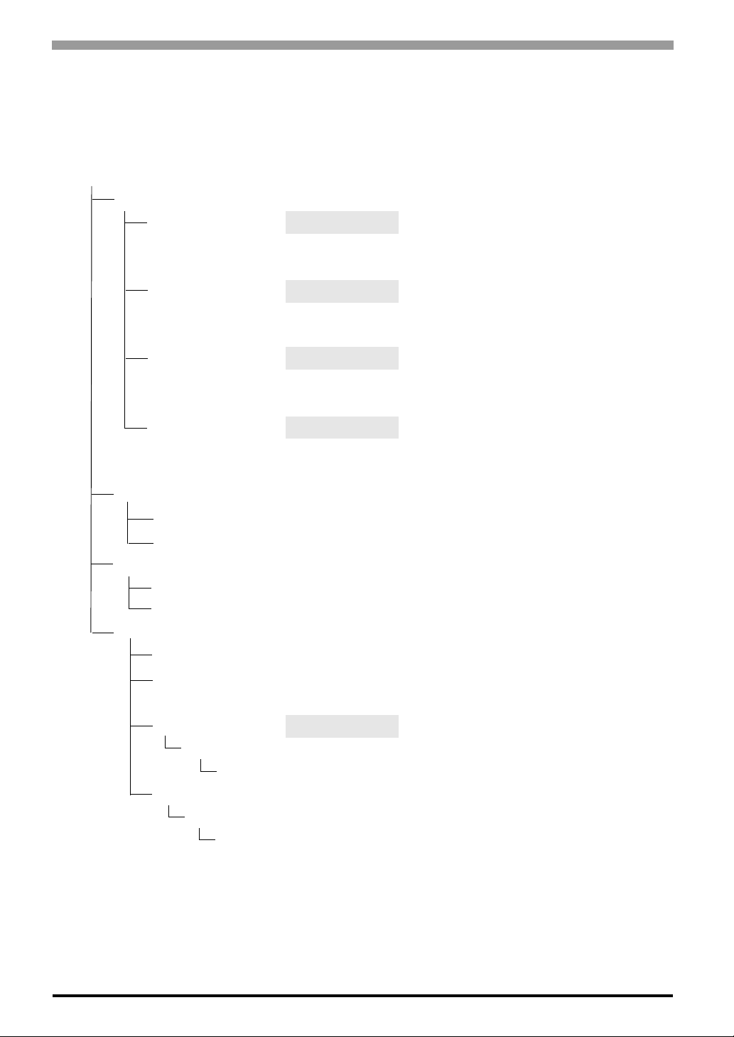
Compact Panel Computer PS-3700A (Eden
4.1 CD-ROM Contents
4.1.1 Software
This section explains the organization of the software included in the accessory CD-ROM.
PS370XA-E66 User Manual & Driver CD
[Driver]
[4 in 1] 4 in 1 Driver <Supported OS types>
[Audio] Audio Driver <Supported OS types>
[Display] Display Driver <Supported OS types>
[USB] USB 1.1 Driver <Supported OS types>
[Manual] <User Manual>
[Eng] PDF Manual (English Version)
[Jpn] PDF Manual (Japanese Version)
[Reader] <PDF Reader>
[Eng] ar505enu.exe Acrobat
[Jpn] ar505jpn.exe Acrobat® Reader (Japanese Version)
[Utility] <PS-A Utility Tools>
[Shutdown] Remote Shutdown Instal l e r
[RASSvr] Remote RAS Server for PC Installer
[Win2000] Utility Setup Windows
[Disk1]
Setup.exe
[WinXP] Windows
[Disk1]
Setup.exe
TM
ESP6000-667MHz Model) User Manual
Windows
Windows
®
2000
®
XP
Windows®2000
Windows
®
XP
Windows®2000
Windows
®
XP
Windows®2000
Windows®XP
®
Reader (English Version)
<Supported OS types>
®
2000
®
XP
4-2

4.2 Setting Up Your PS-A Unit
There are two types of PS-A units. One has a hard disk with no pre-installed OS and one has a hard disk with
a pre-installed OS. Therefore, the setup procedures used will differ. This manual describes only the procedures for setting up a PS-A unit using a hard disk with no pre-installed OS. For an explanation of how to set
up a PS-A using a hard disk with a pre-installed OS, refer to the “Pre-installed Type Installation Guide”, provided with the HDD unit.
4.2.1 Setup Procedures
First, you will need to install either Windows®2000 or Windows®XP. You also need to install any required
utility software.
Installing the HDD Unit
Check to see if a hard disk unit is installed in your PS-A unit. If it is not, please install one prior to going to the
next step.
Chapter 4 Setting up Your PS-A Unit
SEE
PSA-HD20 Installation guide
Setting Up HDD Unit System Information
After you install your HDD unit, you will need set up a variety of system information. Set up this information
so that the system recognizes the newly-installed hard disk drive.
SEE
PSA-HD20 Installation guide
Setting Up the OS
Install your operating system. For detailed setup procedures, refer to that product's installation manual.
• The PS-A unit supports the following two OS. PS-A unit performance cannot be
guaranteed when any other operating system is used.
®
Windows
Windows
2000 Service Pack 4
®
XP Service Pack 1/Service Pack 2
PS-A Utility Setup
Install the necessary drivers and utility software from the “PS370XA-E66 User Manual & Driver CD”.
• A PS/2 (mini-DIN) type keyboard or a USB keyborad is required to install the OS.
• When using a touch panel display with the PS-A, the touch panel will require an optional mouse
emulator (PL-TD000). Before installing the mouse emulator, be sure to specify the Touch
Panel’s Communication Changeover SW settings. Please refer to 1.4.1 RS-232C Interface
(COM1/COM2/COM3/COM4) Switches. After specifying the switch either COM4 or USB,
install the mouse emulator.
4-3

Compact Panel Computer PS-3700A (Eden
Installing Software from the PS370XA-E66 User Manual & Driver CD-ROM
To begin the installation, click on the “Setup.exe” file in your OS’ folder.
®
Example) With Windows
XP
D:\Utility\WinXP\Disk1\Setup.exe (When the CD-ROM drive is “D”)
For Windows
®
PS-A Hard Disk Data
Setting up the PS-A unit’s utilities will create a [Proface] folder on the C drive. The following diagram
describes the configuration of this folder. (For all Windows
[Proface]
[4 in 1] 4 in 1 Driver
[Audio] Audio Driver
[Blsaver] Backlight Control Screen Saver
[Disp] Backl ight Control Console Application
TM
ESP6000-667MHz Model) User Manual
2000, this will be “Win2000”.
®
versions)
(including Chipset, AGP, PCI IRQ Miniport, ATAPI drivers)
[Display] Graphic Accelerator Driver
[Keyclick] Keyboard Emulation Application
[PsaApi] API-DLL
[Shutdown]
[Client] Remote Shutdown Client
[Sysmon] System Monitor/RAS Application
[USB] USB 1.1 Driver
• The actual organization may differ depending on your PS-A unit’s OS.
• Setting up the PS-A unit’s uti lities automatically copies the hardware control driver (Psamon.sys,
Blctrl.sys) to the system folder.
4.2.2 Setting Up an HDD with Pre-installed OS
Use the following steps to set up your PS-A unit’s HDD unit, which contains the Windows®2000 operating
system, related drivers and utility software.
4-4
• Each pre-installed operating system is designed specially for the PS3700A-T41-ASU-E66 unit.
• “Service Pack 4” is included in the Windows®2000 HDD unit.
Chapter 4 Setting up Your PS-A Unit
Installing the HDD Unit
After opening the PS-A unit’s packing box, check that a hard disk unit is installed. If it is not, you will need to
install it.
SEE
Pre-installed HDD Unit Installation Guide
Setting Up the PS-A Unit’s System Information
If your PS-A unit does not have a pre-installed HDD, you will need to install an HDD unit and then configure
that drive’s system information. Be sure to check that the system successfully recognizes the drive.
SEE
Pre-installed HDD Unit Installation Guide
Setting Up an HDD with Pre-installed OS
Follow the setup procedures given in the Pre-installed Type HDD Unit Installation Guide.
PS-A Hard Disk Data
Setting up the PS-A unit’s utilities will create a [Proface] folder on the C drive. The following diagram
®
describes the configuration of this folder. (For all Windows
[Proface]
[4 in 1] 4 in 1 Driver
[Audio] Audio Driver
[Blsaver] Backlight Control Screen Saver
[Disp] Backl ight Control Console Application
versions)
[Display] Graphic Accelerator Driver
[Keyclick] Keyboard Emulation Application
[PsaApi] API-DLL
[Setup] CD Image
[Shutdown]
[Client] Remote Shutdown Client
[Sysmon] System Monitor/RAS Application
[USB] USB 1.1 Driver
• The actual organization may differ depending on your PS-A unit’s OS.
• Setting up the PS-A unit’ s utilities automatically copie s the hardware control driver (Psamon.sys,
Blctrl.sys) to the system folder.
4-5

Compact Panel Computer PS-3700A (Eden
4.3 Installing Drivers
Four types of dedicated PS-A drivers (4 in 1, Audio, graphic accelerator, and USB 1.1) are available.
Install the required drivers from this data when using a PS-A with no pre-installed OS (A PS -A unit that has
been recovered using the Recovery CD-ROM will have all the required drivers installed). This explanation
given in this section assume that the [Proface] folder has been created.
• Once drivers are installed in the PS-A unit, they cannot be uninstalled.
Installing the 4 in 1 Driver
Installing the 4 in 1 driver makes the followings installed; Chipset, AGP, Miniport and ATAPI.
(1) Double-click on the “VIAHyperion4in1448v.exe” file located in the following folder. Follow the
instructions given to install the driver.
C:\Proface\4in1\VIAHyperion4in1448v.exe
Installing the Audio Driver
TM
ESP6000-667MHz Model) User Manual
Installing the Audio driver enables the OS’Audio feature.
(1) Double-click on the “Setup.exe” file located in the following folder. Follow the instructions given to
install the driver.
C:\Proface\Audio\Setup.exe
Installing the Graphic Accelerator Driver
Installing the Graphic Accelerator Driver will ac celerate the screen refresh speed, using special hardware features.
(1) Start “C:\Proface\Display\Setup.exe” file.
(2) Select [Next]-[Yes]-[Exit], and then restart the system to complete the installation.
USB 1.1 Driver Installation
This section describes how to install a USB 1.1 driver into your PS-A unit. Doing so ensures that both bottomface USB connectors (2 ports) and front-face USB connector (1 port) operate as a USB 1.1 port.
(1) Double-click on the “Setup.exe” file located in the following folder. Follow the instructions given to
install the driver.
C:\Proface\USB\Setup.exe
4-6

4.4 Special Application Program Features
The special programs designed for the PS-A unit are located in the following folders.
®
File Name Windows
PSA_RAS.DLL
PSA_DLL.DLL
PSA_IOC.DLL
PSA_BLC.DLL
Backlight Control.scr
Bl Bright.cpl
Disp.exe C:\Proface\Disp
Keyclick.exe C:\Proface\Keyclick
PSA_Smon.exe C:\Proface\Sysmon
PSA_Wps.exe C:\Proface\Sysmon
Psamon.sys
Blctrl.sys
C:\Windows\System32 C:\Winnt\System32
C:\Windows\
System32\Drivers
XP Windows®2000
Chapter 4 Setting up Your PS-A Unit
C:\Winnt\System32\
Drivers
API-DLL
These dynamic link libraries allow users to access RAS features via custom-made applications. The following
four types are available.
Shared Memory Access: PSA_RAS.DLL
This dynamic link library allows users to access shared memory via remote RAS features.
SEE
System Monitoring: PSA_DLL.DLL
This dynamic link library allows users to access the PS-A unit’s system monitor feature.
RAS Features: PSA_IOC.DLL
This dynamic link library allows users to access RAS features via custom-made PS-A applications.
SEE
Backlight Control API-DLL file (PSA_BLC.DLL)
This API-DLL file provides a dynamic library that allows User-created applications to utilize the PS-A backlight control feature. This file must be installed into the same directory as the User’s application.
SEE
For details, refer to the API Reference Manual.
For details, refer to the API Reference Manual.
For details, refer to the API Reference Manual.
4-7

Compact Panel Computer PS-3700A (Eden
TM
ESP6000-667MHz Model) User Manual
System Monitoring/RAS Applications: PSA_Smon.exe/PSA_Wps.exe
The RAS and System Monitoring features allow users to monitor temperature voltage, and fan operation
®
alarms. This program runs on Windows
System Monitoring Program: PSA_Smon.exe
.
SEE
Watchdog Parameter Setup Program: PSA_Wps.exe
SEE
5.2.3 System Monitoring Operation (PSA_Smon.exe) (page5-9)
5.2.2 System Monitoring Property Settings (PSA_Wps.exe) (page5-7)
System File: Psamon.sys
This system file allows use of the RAS and System Monitoring features. This file should not be modified. If it
is modified, the RAS and System Monitoring features may not operate correctly.
Backlight OFF Screen Saver (Backlight Control.scr)
This software is used to turn OFF the PS-A’s backlight after a specified period of inactivity. The use of this
feature will help to extend the life of the PS-A’s backlight.
• Certain application programs may not allow the PS-A’s backlight to turn OFF. Please test each
program individually to check if the screen saver will operate correctly.
Screen Display ON/OFF Utility (DISP.EXE)
This command line utility is used to turn OFF both the PS-A’s backlight and display.
Settings Used DISP [ON/OFF]
Option Switch ON: Displayed / OFF: Not Displayed
Return Value 0: Completed Normally / -1: Option Switch Error
• If your application requires that the OS continuously turn the Windows
display ON and OFF, be sure to use the backlight control dll, PSA_BLC.DLL.
Keyboard Emulator (Keyclick.exe)
This program allows the User’s mouse operation to perform keyboard-like data input.
• Certain application programs do not support this keyboard emulator. Please test each application
individually to check if the keyboard emulator will operate correctly.
• This application cannot be used to enter Windows
information.
• To change the Keyclick program’s font size a keyboard is required.
• For details concerning the Keyclick program’s operation, simply click on the HELP button to
call up the program’s online help data.
4-8
®
backlight
®
startup screen User Name and Password

Backlight Brightness Adjustment (Bl Bright.cpl)
Backlight brightness can be set to one of four levels: Level 0, Level 1, Level 2 or Level 3.
Brightness level 0: Very dark
Brightness level 1: Somewhat dark
Brightness level 2: Somewhat bright
Brightness level 3: Very bright
To use this program, click the [Control Panel]’s [Backlight Brightness] icon.
4.4.1 Uninstalling Utility Software
Utility programs can be uninstalled using the following procedure.
(1) Click on the [Control Panel] icon.
(2) Click on the [Add/Remove Programs] icon and from the list of installed programs that appears, select
[PS370XA-E66 Driver and Utility] and click [Add/Remove].
• Once drivers are installed in the PS-A unit, they cannot be uninstalled.
Chapter 4 Setting up Your PS-A Unit
4-9

Compact Panel Computer PS-3700A (Eden
TM
ESP6000-667MHz Model) User Manual
4.5 When Using Windows®2000/Windows®XP
4.5.1 Automatic System Log-on Setup
This setting allows users to simplify password entry at startup.
Windows®2000
(1) Double-click on the [Control Panel]’s [User and Password] icon.
(2) Designate the automatic logon user, and deselect the [User must enter the user name and password to use
this computer] checkbox.
(3) Click on the [Advanced] tab, and deselect the [Require users to press Ctrl +Alt + Del keys before log-
ging on] checkbox.
(4) Click the [Apply] button. Next, when the automatic logon dialog box appears, enter the password.
Windows®XP
(1) Select [Run] from the [Start] menu.
(2) Enter “Control userpasswords2”, and click [OK].
(3) Deselect the [User must enter the user name and password to use this computer] checkbox and click
[Apply].
(4) Enter the user name and password for automatic logon and click [OK].
• A password must be assigned for user to perform automatic logon.
• If automatic logon is not used, a PS/2 (mini-DIN) type keyboard is required to logon.
4-10

4.5.2 Uninterrupted Power Supply System (UPS)
Be sure to shut down your OS before turning off your machine. Also, use of an uninterrupted power supply is
recommended to protect your data from accidental power failures.
An uninterrupted power supply will give you sufficient time to shut down your system safely in case of a
power failure, and can even be set up to automatically shut down your W ind ows
The PS-A unit, however, cannot be used with a 2-Step Inverter Output type uninterrupted power supply. Be
sure the unit is a sine-output type power supply. For details, consult your local UPS system dealer.
4.5.3 Changing System Settings
Your Windows® system’s configuratio n settings will need to be changed when the PS-A unit is connected to a
LAN network or printer.
Changing the System Configuration Settings
®
When the Windows
name of the folder where you will save the configuration changes and click [OK].
• Insert the CD labeled “Windows
system configuration settings are changed, the following message appears. Enter the
®
xx*1 Professional CD-ROM” in the CD-ROM drive
Chapter 4 Setting up Your PS-A Unit
®
OS.
(D: ), and click [OK].
• When copying the file from other locations such as a floppy disk or network server, also
click the [OK] button.
• When Your PS-A has No Preinstalled OS
Double-click the [I386] folder in the Windows® CD-ROM.
D:\I386 (When the CD-ROM drive is "D")
• When Your PS-A has a Preinstalled OS
C:\Proface\Setup\I386
4.5.4 NTFS File System Conversion
If your PS-A unit has a pre-installed OS, or if your OS is formatted with the Windows® DOS-compatible file
system (FAT32), it can be converted to the NTFS file system.
To convert to the NTFS file system, start up Windows
convert X: /fs:ntfs (Replace “X” with your drive name.)
• Once the file system is converted to the NTFS file system, it cannot be converted back to the
Windows® DOS-compatible file system (F AT32).
®
and use the following command.
*1 “xx” is your OS.
Example) When using Windows
®
XP: “Windows®XP Professional CD-ROM”
4-11

Compact Panel Computer PS-3700A (Eden
Memo
TM
ESP6000-667MHz Model) User Manual
4-12

5 Monitoring
Features
1. RAS Features
2. System Monitor/RAS Features
3. Error Displays When Using Event Viewer
4. Remote RAS
5. Remote Shutdown Feature
5-1
Compact Panel Computer PS-3700A (Eden
5.1 RAS Features
5.1.1 PS-A RAS Features
RAS (Reliability, Availability, Serviceability) features include a variety of useful system performance monitoring features, with the main feature being device monitoring. These features are designed to improve overall
system reliability.
Types of Monitoring
The PS-A unit supports the following Alarm Monitoring features.
Error Monitoring
TM
ESP6000-667MHz Model) User Manual
Power Voltage Alarm
Cooling Fan RPM Alarm
Watchdog Timer Timeup
Touch Panel Alarm
Backlight Alarm
SMART Alarm
Alarm Processing
The PS-A provides the following alarm processing (processing or external output signals) in response to the
previous page's alarms, or to external signal input.
Types of Processing
LED Indicator (2 colors, 1 lamp)
Pop-up Message Output
Buzzer Output
System Shutdown
System Reset
System Monitor
The System Monitor feature (software utilities ) allows users to enable or disable the monitoring of any of the
above monitoring items, as well as to individually set alarm processing settings.
SEE
In addition, System Monitor includes a dynamic link library (API-DLL) feature that gives other applications
access to RAS features.
5.2 System Monitor/RAS Features (page5-6)
5-2

5.1.2 RAS Feature Details
Error Monitoring
Power Voltage Alarm
Monitors the status of the PS-A unit’s built-in power supply and internal CPU power supply.
Cooling Fan Rotation Alarm
Monitors the power-supply and CPU cooling fan RPM speeds.
Watchdog Timer Timeup
This feature monitors the performance of the CPU by writing the CPU’s time-up count value to the RAS feature's built-in programmable timer and by periodically clearing the count value from the CPU. Errors are
detected when the clearing of the count value from the CPU stops, which will cause a timer overflow.
Use the System Monitor Property area to set the Watchdog Timer Timeup ON or OFF , and ente r detailed error
processing settings.
Touch Panel Alarm
Detects Touch Panel alarms. When an alarm occurs, the LED will turn orange.
Chapter 5 Monitoring Features
Backlight Runout Error
Detects Backlight Runout Errors. When an alarm occurs, the LED will flash orange/red.
SMART Alarm
Monitors the status of the hard disk. Detects a warning of trouble of the hard disk.
• Administrator Authentication is required for executing SMART Monitoring.
• A CF card doesn't support SMART and therefore the status of the CF card cannot
be monitored.
• When a hard disk except options made by Pro-face is used, operation of SMART
Monitoring cannot be guaranteed.
• The SMART Monitor can be performed for the hard disk connected to the IDE
only. The state of the hard disk connected via a USB or a SCSI cannot be monitored.
5-3

Compact Panel Computer PS-3700A (Eden
Types of Processing
Detects Backlight alarms. When an alarm occurs, the LED will flash orange/red.
LED Indicator
The three-color LED is used to indicate PS-A system conditions. It is also used as a power ON/OFF indicator.
The LED is located on the front face of the PS-A unit.
LED Color System Status Outpu t Cr eated
Green (Lit) Normal Operation (Power ON) None
Orange (Lit)
Orange/Red (Lit) Backlight is not functioning. None
• Immediately after the PS-A unit's power is turned ON, if the orange LED lights, a Touch Panel
Self-Test Error may have occurred.
Pop-up Message Output
This feature displays system status via a Windows
A RAS alarm has occurred.
Touch Panel Self-Test Error None
TM
ESP6000-667MHz Model) User Manual
LED is enabled via System Monitor Property.
®
pop-up message.
System Monitor Property is used to enable or disable this feature.
Buzzer Output
This feature uses the PS-A unit’s built-in speaker to alert the operator about PS-A system status.
System Monitor Property is used to enable or disable this feature.
System Shutdown
This feature shuts down the PS-A unit’s OS.
System Monitor Property is used to enable or disable this feature.
System Reset
This feature resets the system when the Watchdog Timer reaches “time up”.
System Monitor Property is used to enable or disable this feature.
5-4

5.1.3 RAS Feature Overview
*1
BIOS Setup
Voltage, Fan RPM,
Detection Settings
Enable/Disable
System Properties
Power Alarm, Fan Alarm,
Output Settings,
Watchdog Timer Value Settings,
Watchdog Reset Enable/Disable
System Monitor
*1
Popup
Message
*2
Chapter 5 Monitoring Features
*2
OS Shutdown
User
Application
BIOS
System Alarm
Data
System Monitoring Application
Driver or API-DLL
*2
Buzzer
Touch Panel Self-Test Error
Green: Power ON
Orange: RAS Error
Orange/Red: Backlight Error
*2
LED
Watchdog
WDT Reset
Mask Settings
Reset Control
Timer
Hardware
Reset
Hardware
*1 Be sure to adjust these setti ngs ac cording to your system’s specifications.
SEE
5.2 System Monitor/RAS Features (page5-6)
*2 Output via the RAS feature.
5-5

Compact Panel Computer PS-3700A (Eden
TM
ESP6000-667MHz Model) User Manual
5.2 System Monitor/RAS Features
5.2.1 Setup Procedures
Follow the steps below to enable the System Monitor/RAS features.
Via System Monitor Setup Screen
Use the [System Monitor Setup] menu’s System Setup screen to enable or disable monitoring features.
SEE
3.2.9 System Monitor Setup (page3-20)
Phoenix AwardBIOS CMOS Setup Utili ty
System Monitor Setup
Warning Voltage +3.3V [Disabled]
Warning Voltage +5V [Disabled]
Warning Voltage +12V [Disabled]
Warning Voltage -12V [Disabled]
CPU Fan Speed Limit [Disabled]
System Fan Speed Limit [Disabled]
Power Fan Speed Limit [Disabled]
↑↓→←: Move Enter: Select +/-/PU/PD: Value F10: Save ESC: Exit F1: General Help
F5: Previous Values F6:Fail-Safe Defaults F7: Optimized Defaults
Item Help
Menu Level 4
Via Applications
Start the PS-A unit’s OS and start up the System Monitor Property using the [S tart] → [Programs] → [System
Monitor] → [System Monitor Property] commands. Next, set the processing to be performed when a System
5-6
Monitor/RAS event occurs.
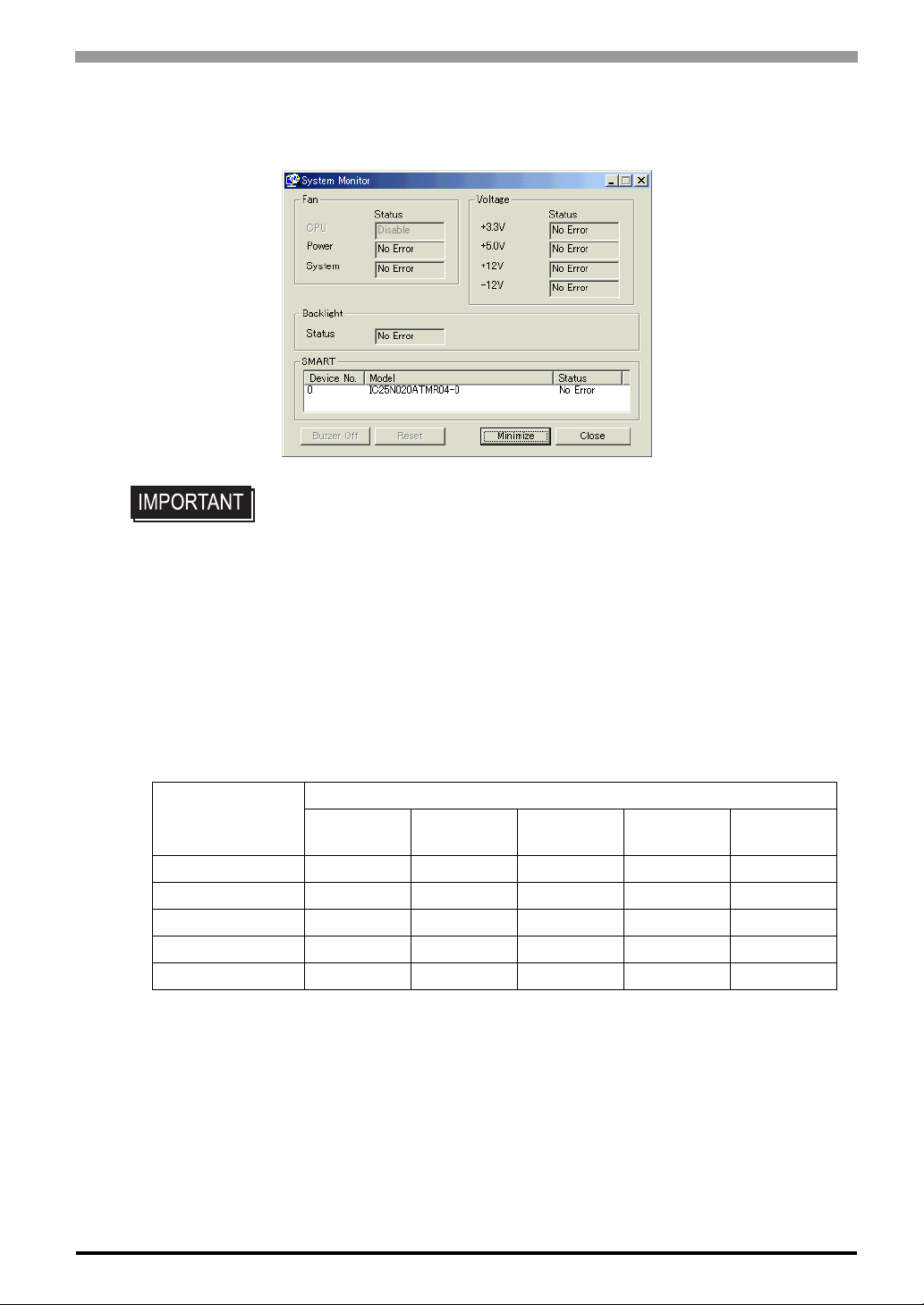
Chapter 5 Monitoring Features
System status can be monitored at any time via the System Monitor. Select [Start] → [Programs] → [System
Monitor]
• Administrator Authentication is required for executing SMART Monitoring. When
a user who does not have the administrator authentication logs in, nothing is displayed in the item of SMART.
5.2.2 System Monitoring Property Settings (PSA_Wps.exe)
The System Monitor Property screen allows you to configure the operating settings that are activated when
system conditions exceed the allowable range (when an error occurs) of each monitoring device specified on
the [System Monitor Setup] menu on the System Setup screen.
The following table lists the operating settings that can be configured for each feature.
O: Setting available X: Setting not available
Operation
Feature
Watchdog Timer O O O O O
Voltage O O O X O
Fan O O O X O
Backlight O O X X O
SMART O O X X O
Buzzer
Popup
MessageOSShutdown
OS
Reset
LED
5-7

Compact Panel Computer PS-3700A (Eden
The following table lists the description of each operation.
Item Operation
TM
ESP6000-667MHz Model) User Manual
Buzzer
Pop-up Message
OS Shutdown Shuts down the operating system.
OS Reset Restarts the operating system.
Enable
LED The front orange LED lights
The following is the overview of the System Monitor Property setting screen.
Enable of disable the
feature.
Specify the operation to
be performed when the
condition exceeds the
allowable range.
Sounds a beep as an alarm. (Cannot be set up when a checkmark is put to
the "OS Shutdown" checkbox.
Displays error messages as pop-up messages. (The messages pop up on
the screen.)
Select or deselect this option to enable or disable each setting of the monitoring feature.
Set the timer
Enter the message to be
displayed as a pop-up
message.
5-8
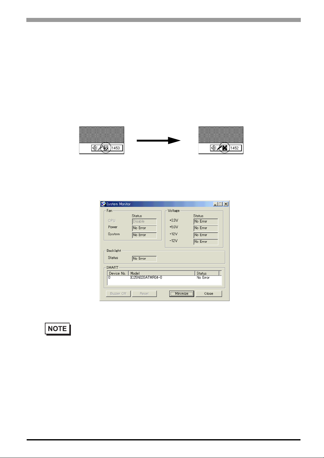
5.2.3 System Monitoring Operation (PSA_Smon.exe)
The System Monitor screen will not be displayed immediately after the System Monitor is started, instead, the
icon will be stored in the System Tray.
When and error is detected, the “Operations (buzzer, pop-up message output, etc.)” set on the System Monitor
Property are performed, and then an “X” mark appears on the icon on the System Tray, which indicates an
error status. When the icon on the System Tray changes as illustrated below, double-click on the icon to
review the description of the error condition.
Chapter 5 Monitoring Features
Icon display upon
start-ups
The following is the System Monitor screen.
System Monitor Screen
• As for Device No. of SMART, [0] means Master and [1] means Slave.
Icon display when an
error is detected.
5-9

Compact Panel Computer PS-3700A (Eden
The [Buzzer Off], [Reset], [Minimize], [Close] buttons are located at the bottom of the System Monitor
screen. The following table lists the features of the buttons.
Button Operation
Buzzer Off Stops the buzzer sounds at normal operations.
Reset
Minimize Minimize the System Monitor into the icon display.
Close Closes the System Monitor.
The System Monitor screen displays whether the each parameter of “F AN/VOLTAGE/SMAR T” is disabled or
in normal/abnormal condition. The following table lists the status to be displayed.
Clears the error condition held at normal operations and inside the
System Monitor.
Display Meaning
No Error Normal
Error Abnormal
Disable Monitoring disabled
Not Support Not support
TM
ESP6000-667MHz Model) User Manual
• [Not Support] is displayed when a device like a CF card, which does not support SMART, is
detected.
The system performs the Error Action set in the System Monitor Property when an error condition is detected
with each monitoring item.
SEE
The Error Action is performed only one time when an error is detected for each monitoring item.
5.2.2 System Monitoring Property Settings (PSA_Wps.exe) (page5-7)
5-10

Chapter 5 Monitoring Features
For example, look at the “+3.3 V” and “+5.0 V” options in the Voltage field. When the pop-up message feature for monitoring the voltage status is enabled, the pop-up message “+3.3 V Power Supp ly Error” appears
on the screen when the +3.3 V power supply error occurs. Press the [OK] button on the dialog box to hide the
message. The “+3.3 V Power Supply Error” will not appear even when a +3.3 V power supply error occurs
again. However, when a +5.0 V power supply error occurs, the pop-up message “+5.0 Power Supply Error”
appears on the screen. The pop-up message displays the monitored item and error description. When the
buzzer feature is enabled, press the [Buzzer Off] button on the pop-up message to stop the buzzer sound. Press
the [OK] button to close the pop-up message.
Output Screen of Pop-up Message
When “OS Shutdown” is enabled, the system automatically enters the shutdown operation without prompting
the confirmation message for the user. To display the System Monitor screen for reviewing the current condition, double-click on the icon on the System Tray.
When the buzzer sounds as an Error Action, the System Monitor screen displays the [Buzzer Off] button that
is hidden under normal conditions. When a pop-up message window is displayed, the [Buzzer Off] button
appears on the window.
• Once an error is detected, the System Monitor holds the “error” status. (Displays
the icon indicating the error status.) To recover from the error status, press the
[Reset] button on the System Monitor screen, of turn off the PS-A, perform maintenance service for removing the cause of the error, and then turn on the power
again.
5-11

Compact Panel Computer PS-3700A (Eden
5.2.4 Error Messages
This section describes the error message and closing messages displayed on the System Monitor and System
Monitor Property screens.
System Monitor
Error Pop-up Message
When an error occurs while the “Popup Message” option is enabled for Error Action, the following messages
appears on the pop-up screen output screen under the factory-configured settings.
Error-generating Item Message
+3.3V Voltage "+3.3V Power Supply Error"
+5.0V Voltage "+5V Power Supply Error"
+12V Voltage "+12V Power Supply Error"
-12V Volt age "-12V Power Supply Error"
Power FAN "Power FAN Error"
CPU FAN "CPU FAN Error"
System FAN "System F AN Error"
Watch dog "Watch Dog Timer Error"
Backlight "Backlight Error"
SMART “SMART Error”
TM
ESP6000-667MHz Model) User Manual
• The messages displayed on the pop-up message output screen can be modified on the System
Monitor Property screen.
Driver Non-Opera tio n Error
“The System Monitor driver not found.”
“Install the latest driver.”
Driver Version Error
“The old System Monitor driver version.”
“Update the driver.”
Overlapped Startup Message
“System Monitor has started.”
“Terminate the System Monitor in starting.”
Closin g Confirmation Message
“The System Monitor is terminated.”
“Are you sure?”
5-12

System Monitor Property
Overlapped Startup Message
“System Monitor property has started.”
“Te r minate the System Monitor Property.”
Closing Confirmation Message
“Save Changes to the registry?”
Chapter 5 Monitoring Features
5-13
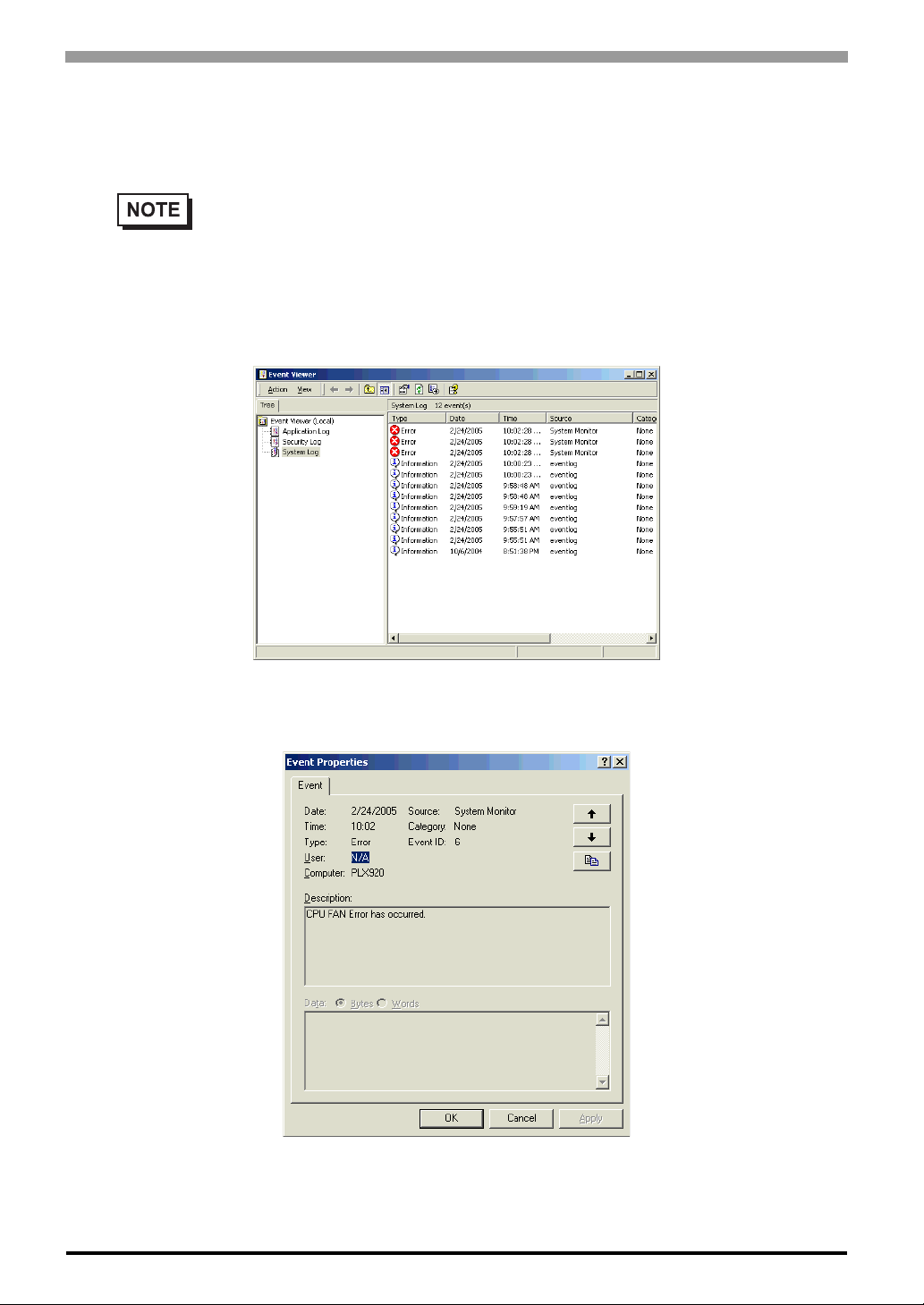
Compact Panel Computer PS-3700A (Eden
TM
ESP6000-667MHz Model) User Manual
5.3 Error Displays When Using Event Viewer
Error type/location and error actions are recorded as error events in the System Log. Error event information
can be checked using the Event Viewer.
• This feature can be used with Windows® 2000, Windows® XP.
5.3.1 Error Message Display
(1) Start the [Control Panel]->[Administrative Tools]->[Event Viewer], and sele ct [System Log].
(2) Select the System Monitor’s error and click the [Properties] icon. When the [Event Properties] dialog
box appears, the error message will appear in the [Description] area.
5-14

5.3.2 Error Type/Location
The error types/locations shown by the Event Viewer are as follows.
Error Type/Location Error Message
+3.3V +3.3V Error has occurred.
+5.0V +5.0V Error has occurred.
+12V +12V Error has occurred.
-12V -12V Error has occurred.
CPU FAN CPU FAN Error has occurred.
Power FAN Power FAN Error has occurred.
System FAN System FAN Error has occurred.
Watch Dog Timer Watch Dog Timer Error has occurred.
Backlight Backlight Error has occurred.
SMART
Chapter 5 Monitoring Features
SMART Error has occurred. Attribute (No.) (Attribute Name)
Device (No.) (HD Model).
The descriptions in the parentheses vary depending on details
of occurring errors and the device having errors occur (0:Master, 1:Slave).
5.3.3 Error Action
Using the Event Viewer the following actions can be taken when an error occurs.
• The data shown in the table’s “” indicate the error type/location.
• The actions to take after an error occurs are set via the System Monitor Property screen.
Error Action Error Message
Buzzer Buzzer has sounded because of error.
Popup Message Popup Message has been shown because of error.
OS Shutdown Window has been shut down because of error.
LED LED has changed to orange because of error.
When a”+3.3V” error occurs and the buzzer sounds, two errors will be displayed, “+3.3V Error has occurred.”
and “Buzzer has sounded because of +3.3V error”.
5-15

Compact Panel Computer PS-3700A (Eden
5.4 Remote RAS
The Remote RAS feature uses the Pro-face’s Pro-Server with Pro-Studio (optional) installed in the host PC to
monitor and control the System Monitor/RAS feature of the PS-A.
Pro-Server with Pro-Studio Ver.3.12 of higher is required to use the Remote RAS feature. When using this
feature, refer to the installation guides provided with the Pro-Server as well as this manual.
5.4.1 System Configuration
The system employing this feature is configured as illustrated below.
Server PC
TM
ESP6000-667MHz Model) User Manual
User Application
Two-way feature
Client PS-A
Pro-Server with Pro-Studio Ver.3.12 or higher
Remote RAS Server Program (PSA_RAS.npj)
Ethernet
[System Monitor/RAS Feature]
• PSA_Smon.exe
• PSA_Wps.exe
• PSA_Ioc.dll
• PSA_DLL.dll
• PSA_Ras.dll
• PSA_Blc.dll
• Psamon.sys
5-16

5.4.2 Installation Procedures
On the server PC, start up the “Setup.exe” file in the [RASSvr] folder on the accessory CD-ROM, and then
install the program by following the instructions on the screen.
5.4.3 Setup and Preparation of the Remote RAS Feature
In order to monitor the System Monitor/RAS features from the server PC, you are required to set up the
Remote RAS feature and start up the System Monitor (PSA_Smon.exe).
Setting Up the Client PS-A
(1) Select [Start] → [Programs] → [System Monitor] → [System Monitor Property] commands to start the
System Monitor Property.
(2) On the [Remote RAS] tab, put a check mark to the [Enable] checkbox.
IP Address used to
connect with
Pro-Server*
1
Chapter 5 Monitoring Features
Put check marks
on the items you
want to monitor.
This feature designates that the PS-A
will communicate
only with the server
at the specified IP
address.
The Remote RAS feature is now enabled.
• In order to actually activate the Remote RAS feature, you are required to start up the System
Monitor (PSA_Smon.exe) within the PS-A.
*1 When allocating 2 or more IP Addresses to the PS-A unit, [Auto] cannot be selected. Enter settings that
allow the reading of a fixed IP Address from a DHCP server. For details, contact your company’s network administrator.
Specify the IP
address of the
server you want to
communicate with.
5-17
 Loading...