

Page 1

Easy! Smooth!
GP-2300 Series->GP4000 Series
Replacement Guidebook
1/59
Copyright © 2012.9 Digital Electronics Corporation. All Rights Reserved.
4th Edition Jul. 2012
Page 2

Preface
This guidebook introduces the procedures to replace a unit in GP-2300 series with a
GP-4301T/TW unit.
Model in use Recommended Substitution
GP-2300T/S GP-4301T
GP-2300L
GP-4301TW
GP-2301T/S/L
2/59
Page 3

GP4000 Series Model Number
GP4000 series model number partly differs depending on a specification. Before
placing an order, please make sure of the model number.
A 2 GP-4200 series (3.5”)
3 GP-4300 series (5.7”)
4 GP-4400 series (7.5”/7.0”W)
5 GP-4500 series (10.4”)
6 GP-4600 series (12.1”)
B 01 RS-232C/422/485
03 RS-485 (isolation)
C T TFT color LCD
W TFT color LCD (Wide Type)
D A Analog Resistive Film Touch Panel
M Matrix Resistive Film Touch Panel
E A AC Type Power Supply
D DC Type Power Supply
F W GP-4201TW/4301TW/4401WW/4501TW
C Coated model
WC Coated model of GP-4301TW
3/59
Page 4

Contents
PREFACE 2
GP4000 SERIES MODEL NUMBER 3
CONTENTS 4
CHAPTER 1 SPECIFICATION COMPARISON 6
1.1 SPECIFICATIONS OF GP-2300T/S AND GP-4301T 6
1.2 SPECIFICATIONS OF GP-2300L AND GP-4301TW 8
1.3 SPECIFICATIONS OF GP-2301T/S/L AND GP-4301TW 10
CHAPTER 2 COMPATIBILITY OF HARDWARE 12
2.1 LOCATIONS OF CONNECTOR 12
2.2 TOUCH PANEL SPECIFICATIONS 18
2.3 DISPLAY COLORS (FOR GP-2300L/2301L ONLY) 19
2.4 TRANSFER CABLE 20
2.5 INTERFACE 20
2.5.1 SERIAL INTERFACE 20
2.5.2 CF CARD INTERFACE 21
2.6 PERIPHERAL UNITS AND OPTION UNITS 21
2.6.1 BARCODE READER CONNECTION 21
2.6.2 PRINTER CONNECTION (FOR GP-2300T/S/L ONLY) 21
2.6.3 EXPANSION UNIT 22
2.6.4 ISOLATION UNIT 22
2.7 POWER CONNECTOR 22
2.8 BACKUP BATTERY (ONLY WHEN REPLACING WITH GP-4301T) 22
2.9 POWER CONSUMPTION 23
2.10 MATERIALS/COLORS OF THE BODY 23
2.11 BACKUP MEMORY (SRAM) 24
4/59
Page 5

CHAPTER 3 REPLACEMENT PROCEDURE 25
3.1 WORK FLOW 25
3.2 PREPARATION 26
3.3 RECEIVE SCREEN DATA FROM GP-2300 SERIES 27
3.4 CONVERT SCREEN DATA WITH THE PROJECT CONVERTER 31
3.5 CHANGE THE DISPLAY UNIT TYPE 38
3.6 TRANSFER SCREEN DATA TO GP-4301T/TW 39
3.7 DIFFERENCES OF SOFTWARE 44
3.7.1 DIFFERENCES AFTER CONVERSION 44
CHAPTER 4 COMMUNICATION WITH DEVICE/PLC 46
4.1 DRIVERS 46
4.2 SHAPES OF COM PORTS 46
4.3 SIGNALS OF COM PORTS 47
4.3.1 SIGNALS OF COM1 47
4.3.2 SIGNALS OF COM2 49
4.4 MULTILINK CONNECTION 50
4.5 INTERNAL 2-PORT FEATURE FOR MITSUBISHI PLC 50
4.6 CABLE DIAGRAM AT THE TIME OF REPLACEMENT 51
4.6.1 WHEN USING A RS-232C CONNECTION CABLE 52
4.6.2 WHEN USING A RS-422 CONNECTION CABLE 55
CHAPTER 5 APPENDIX 57
5.1 CHANGING THE SETTING OF THE EXTERNAL MEDIA TO USE 57
5/59
Page 6

Chapter 1 Specification Comparison
1.1 Specifications of GP-2300T/S and GP-4301T
GP-2300T/S GP-4301T
Display
Type
GP-2300T TFT Color LCD
TFT Color LCD
GP-2300S STN Color LCD
Display
Colors,
Levels
GP-2300T
256 colors (without blink)/
64 colors (with blink)
UP!
65,536 colors (without blink)/
16,384 colors (with blink)
->See 2.3
GP-2300S 64 colors
Display Resolution QVGA (320x240 pixels)
Panel Cutout
Dimensions (mm)
156(W)x123.5(H)
External Dimensions
(mm)
171(W)x138(H)x60(D) 169.5(W)x137(H)x59.5(D)
Touch Panel Type Resistive film (Matrix)
NEW! Resistive film (Analog)
->See 2.2
Memory
Application 2MB UP! 16MB
SRAM 256KB UP! 320KB
Backup Battery
Secondary Battery
(Rechargeable Lithium
battery)
NEW!
Primary Battery
(Replaceable Lithium battery)
->See 2.8
Rated Input Voltage DC 24V
Serial
I/F
COM1
D-Sub 25 pin (socket)
RS-232C/422
D-Sub 9 pin (plug)
RS-232C
->See 2.5.1
and Chapter4
COM2
D-Sub 9 pin (plug)
RS-232C
D-Sub 9 pin (plug)
RS-422/485
->See 2.5.1
and Chapter4
6/59
Page 7

Ethernet I/F 10BASE-T UP! 10BASE-T/100BASE-TX
CF Card I/F
✔
- ->See 2.5.2
SD Card I/F -
NEW! ✔
USB
I/F
Type A
-
NEW! ✔
->See 2.4
Type mini B
Tool Connector I/F
✔
-
Printer I/F
Centronic-compliant
(parallel)
- ->See 2.6.2
Expansion Unit I/F
✔
- ->See 2.6.3
7/59
Page 8

1.2 Specifications of GP-2300L and GP-4301TW
GP-2300L GP-4301TW
Display Type Monochrome LCD TFT Color LCD
Display Colors, Levels
Monochrome 2 levels/
monochrome 8 levels
UP!
65,536 colors (without blink)/
16,384 colors (with blink)
->See 2.3
Display Resolution QVGA (320x240 pixels)
Panel Cutout
Dimensions (mm)
156(W)x123.5(H)
External Dimensions
(mm)
171(W)x138(H)x60(D) 169.5(W)x137(H)x59.5(D)
Touch Panel Type Resistive film (Matrix)
NEW!
Resistive film (Analog)
->See 2.2
Memory
Application 2MB UP! 8MB
SRAM 256KB 128KB ->See 2.11
Backup Battery Secondary Battery (Rechargeable Lithium battery)
Rated Input Voltage DC 24V
Serial
I/F
COM1
D-Sub 25 pin (socket)
RS-232C/422
D-Sub 9 pin (plug)
RS-232C
->See 2.5.1
and Chapter4
COM2
D-Sub 9 pin (plug)
RS-232C
D-Sub 9 pin (plug)
RS-422/485
->See 2.5.1
and Chapter4
Ethernet I/F 10BASE-T UP! 10BASE-T/100BASE-TX
CF Card I/F
✔
- ->See 2.5.2
USB
I/F
Type A
-
NEW! ✔
->See 2.4
Type mini B
8/59
Page 9

Tool Connector I/F
✔
-
Printer I/F
Centronic-compliant
(parallel)
- ->See 2.6.2
Expansion Unit I/F
✔
- ->See 2.6.3
9/59
Page 10

1.3 Specifications of GP-2301T/S/L and GP-4301TW
GP-2301T/S/L GP-4301TW
Display
Type
GP-2301T TFT Color LCD
TFT Color LCD
GP-2301S STN Color LCD
GP-2301L Monochrome LCD
Display
Colors,
Levels
GP-2301T
256 colors (without blink)/
64 colors (with blink)
UP!
65,536 colors (without blink)/
16,384 colors (with blink)
->See 2.3
GP-2301S 64 colors
GP-2301L
Monochrome, 2 levels/
Monochrome, 8 levels
Display Resolution QVGA (320x240 pixels)
Panel Cutout
Dimensions (mm)
156(W)x123.5(H)
External Dimensions
(mm)
171(W)×138(H)×60(D) 169.5(W)×137(H)×59.5(D)
Touch Panel Type Resistive film (Matrix)
NEW!
Resistive film (Analog)
->See 2.2
Memory
Application 1MB UP! 8MB
SRAM 128KB 128KB
Backup Battery Secondary Battery (Rechargeable Lithium battery)
Rated Input Voltage DC 24V
Serial
I/F
COM1
D-Sub 25 pin (socket)
RS-232C/422
D-Sub 9 pin (plug)
RS-232C
->See 2.5.1
and Chapter4
COM2 -
D-Sub 9 pin (plug)
RS-422/485
->See 2.5.1
and Chapter4
10/59
Page 11

Ethernet I/F -
NEW!
10BASE-T/100BASE-TX
CF Card I/F
✔
- ->See 2.5.2
USB
I/F
Type A
-
NEW! ✔
->See 2.4
Type mini B
Tool Connector I/F
✔
-
Expansion Unit I/F
✔
- ->See 2.6.3
11/59
Page 12

Chapter 2 Compatibility of Hardware
2.1 Locations of connector
Connector locations on GP-2300 series and GP-4301T/TW are as follows:
GP-2300T/S
GP-4301T
12/59
Page 13

Interface names
GP-2300T/S GP-4301T
1 Power Input Terminal Block Power Connector
2 Serial Interface (COM1)
3 Serial Interface (COM2) Serial Interface (COM2)
4 Tool Connector 5 Ethernet I/F
6 - USB Interface (Type A)
7 - USB Interface (Type mini B)
8 - SD Card Interface
9 CF Card Interface -
10 Expansion Unit Interface 11 Printer Interface -
13/59
Page 14

GP-2300L
GP-4301TW
14/59
Page 15

Interface names
GP-2300L GP-4301TW
1 Power Input Terminal Block Power Connector
2 Serial Interface (COM1)
3 Serial Interface (COM2) Serial Interface (COM2)
4 Tool Connector 5 Ethernet Interface
6 - USB Interface (Type A)
7 - USB Interface (Type mini B)
8 CF Card Interface 9 Expansion Unit Interface -
10 Printer Interface -
15/59
Page 16

GP-2301T/S/L
GP-4301TW
16/59
Page 17

Interface names
GP-2301T/S/L GP-4301TW
1 Power Input Terminal Block Power Connector
2 Serial Interface (COM1)
3 - Serial Interface (COM2)
4 Tool Connector 5 - Ethernet Interface
6 - USB Interface (Type A)
7 - USB Interface (Type mini B)
8 CF Card Interface 9 Expansion Unit Interface -
17/59
Page 18

2.2 Touch Panel specifications
GP-4301T/TW adopts the Analog type. Because of it, simultaneous 2-point touch
input operaion is not supported. When simultaneous 2-point touch input operation is
performed, GP's operation is as described below.
GP-4301T: Only the first detected touch is effective.
GP-4301TW: When two different points are pushed at the same
time,touch input on the middle coordinates between
those two points is recognized.
If you have used the 2-point touch input on GP-2300 series, change to the 1-point
touch input setting using the switch delay function of GP-Pro EX.
18/59
Page 19
2.3 Display Colors (for GP-2300L/2301L only)
The display color of GP-2300L/2301L is monochrome, but GP-4301T/TW has a TFT
color LCD. After replacement, the display color changes from monochrome to color.
When data of a monochrome model is converted to data of a color model with GP-Pro
EX, the data may be displayed in colors depending on the version of the Project
Converter or settings of the drawing/the parts on the screen.
After conversion, please confirm the display colors of the drawing or the parts on the
screens just in case.
If the display is in colors after the data conversion to GP-4301T/TW…
GP-Pro EX Ver. 3.01.200 (Service Pack1) or later supports the function which
changes drawing in colors to in monochrome. T o change the setting, follow the steps
below.
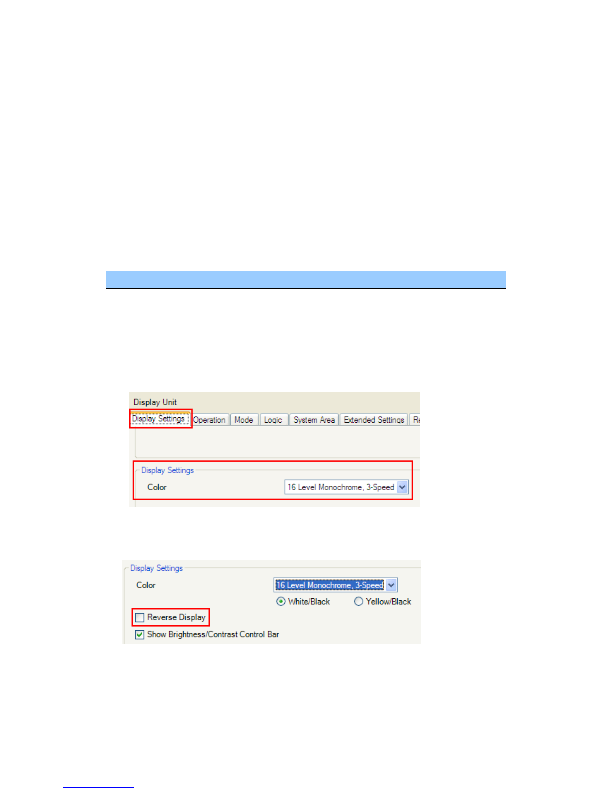
(1) Click [Project]->[System Settings]->[Display Unit].
(2) Open the [Display Settings] tab.
(3) Change [Color] setting to “16 Levels Monochrome, 3-Speed Blink”.
* [Reverse Display] setting is for displaying the screen with black/white reversed.
Check on it if needed.
* Please confirm the display colors of the drawing or the parts on the screens after
changing the [Color] setting to “16 Levels Monochrome, 3-Speed Blink”.
19/59
Page 20
2.4 Transfer cable
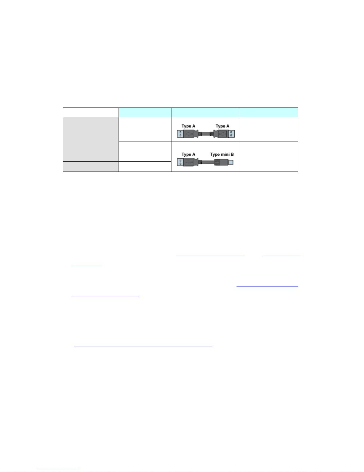
To transfer screen data to GP-4301T/TW, use a USB transfer cable or Ethernet.
The USB cables that can be used for GP-4301T/TW are as follows:
Model Connector Type Connector on GP
Options
CA3-USBCB-01
USB (Type A)
ZC9USCBMB1
USB (Type mini B)
Commercial Item
-
Please note that the cables (GPW-CB02, GPW-CB03, GP430-CU02-M) for GP-2300
series cannot be used for GP-4301T/TW.
2.5 Interface
2.5.1 Serial Interface
The pin assignment and the shape of plug/socket connector of GP-2300 series are
different from those of GP-4301T/TW.
T o know the details about them, se e [4.2 Shapes of COM ports
] and [4.3 Signals of
COM ports].
Because of it, the existing PLC connection cables cannot be used as they are. If you
use the existing connection cables for GP-4301T/TW, see [4.6 Cable Diagram at
the time of replacement].
And even though the both COM1 and COM2 ports on GP-23 00T/S/L are used with
RS-232C setting, only the COM1 port can be used for GP-4301T/TW. In this case,
please contact our sales office in your region.
(http://www.pro-face.com/customer/contact.html
)
20/59
Page 21
2.5.2 CF Card Interface
GP-4301T/TW is not equipped with a CF card slot. But a SD card slot (for GP-4301T
only) and a USB interface are installed. In order to use the GP-2300 series data
saved in the CF card and the functions using the CF card, use a SD card or USB
flash drive for GP-4301T/USB flash drive for GP-4301TW instead.
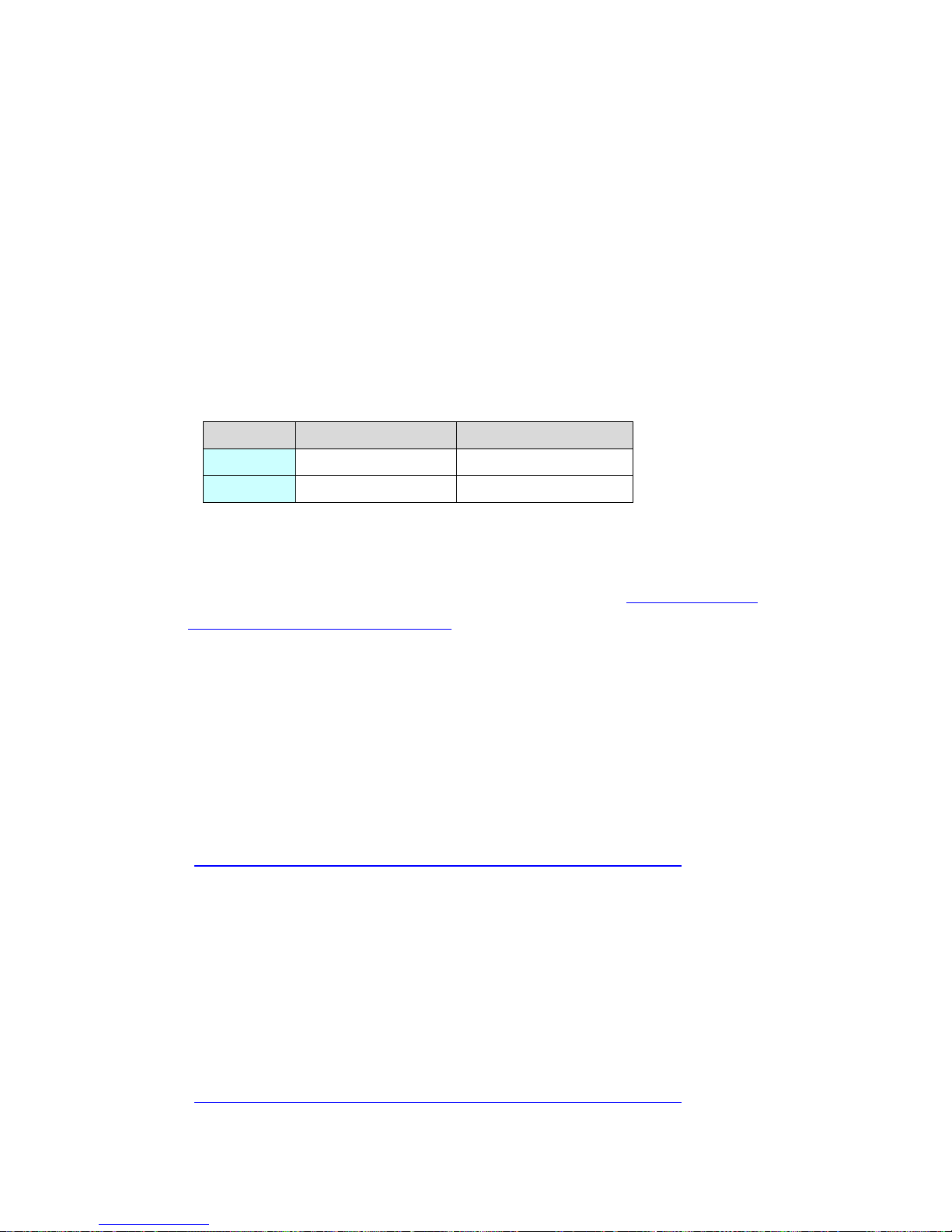
* When using a SD card with GP-4301T, please verify it supports the following
specifications:
File forma Maximum capacity
SD FAT16 2GB
SDHC FAT32 32GB
For the GP-PRO/PBIII’s “CF Card output folder” setting, if project file is converted
on GP-Pro EX, the setting will automatically change to the one that uses a SD card.
To change the setting of the output destination folder, see [5.1 Changing the
setting of the external media to use].
2.6 Peripheral units and option units
2.6.1 Barcode reader connection
GP-4301T/TW is not equipped with a tool port. A barcode reader that used to be
connected to the tool port on GP-2300 series cannot be used. However,
GP-4301T/TW allows you to connect a barcode reader on its USB interface (T ype A)
or its serial interface.
For the models GP-4301T/TW supports, see [OtasukePro!]
(http://www.pro-face.com/otasuke/qa/3000/0056_connect_e.html
).H
2.6.2 Printer Connection (for GP-2300T/S/L only)
GP-4301T/TW is not equipped with Centronics (parallel) Interface for a printer
though GP-2300T/S/L is equipped with it. If the printer for GP-2300T/S/L is used
for GP-4301T/TW, a converter that converts USB I/F on GP-4301T/TW to
Centronics I/F is required. And GP-4301T/TW allows you to connect a printer on its
USB port.
For the models GP-4301T/TW supports, see [OtasukePro!]
(http://www.pro-face.com/otasuke/qa/3000/0056_connect_e.html
).
21/59
Page 22
2.6.3 Expansion Unit
GP-4301T/TW is not equipped with an expansion unit interface. The expansion unit
(each kind of unit like CC-LINK Unit) for GP-2300 series cannot be used.
2.6.4 Isolation Unit
The isolation unit for GP-2300 series (CA2-ISOALL232-01, CA2-ISOALL422-01)
cannot be used for GP-4301T/TW. You can use the RS-232C isolation unit for
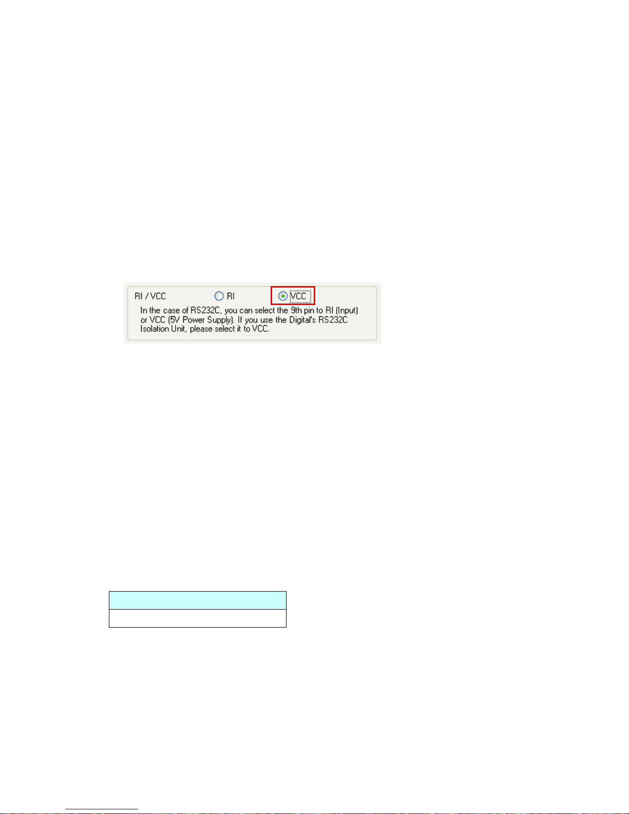
GP-4301T/TW (CA3-ISO232-01) instead. In this case, select “VCC” from [System
Settings] -> [Device/PLC] in the [Project] menu on GP-Pro EX.
2.7 Power Connector
The power connector on GP-4301T/TW is a spring lock type. If you replace GP-2300
series with GP-4301T/TW, change the power cable.
2.8 Backup Battery (only when replacing with GP-4301T)
Unlike GP-2300 series, GP-4301T does not use rechargeable secondary batteries but
replaceable primary ones. (For both a rechargeable type and a replaceable one,
contents to be backed up are the same.)
When the time for replacement of backup batteries approaches, the message to urge
you to replace the battery, “RAAA053: Running out of power in the backup battery.
Please change the battery .” appears. When the message appears, replace the battery
referring to the GP4000 series hardware manual.
Replaceable Battery Model
PFXZCBBT1
22/59
Page 23
2.9 Power Consumption
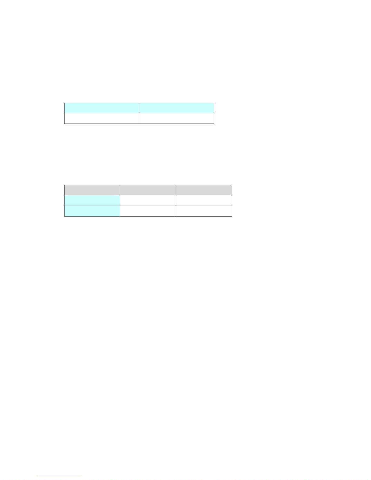
The power consumption of GP-2300 series is different from that of GP-4301T/TW.
GP-2300 series GP-4301T/TW
22W or less 10.5W or less
For the detailed electric specifications, see the hardware manual.
2.10 Materials/Colors of the body
The materials and the colors of GP-2300 series and GP-4301T/TW are as follows:
Color Material
GP-2300 series Silver Aluminum alloy
GP-4301T/TW Light Gray Resin with glass
23/59
Page 24
2.11 Backup Memory (SRAM)
When replacing GP-2300L with GP-4301TW, SRAM size becomes smaller (256KB ->
128KB). In case that SRAM size of your project file is more than 128KB after
converting GP-2300L project file (*.prw) with GP-Pro EX Project Converter, replace
GP-2300L with GP-4301T instead of GP-4301TW.
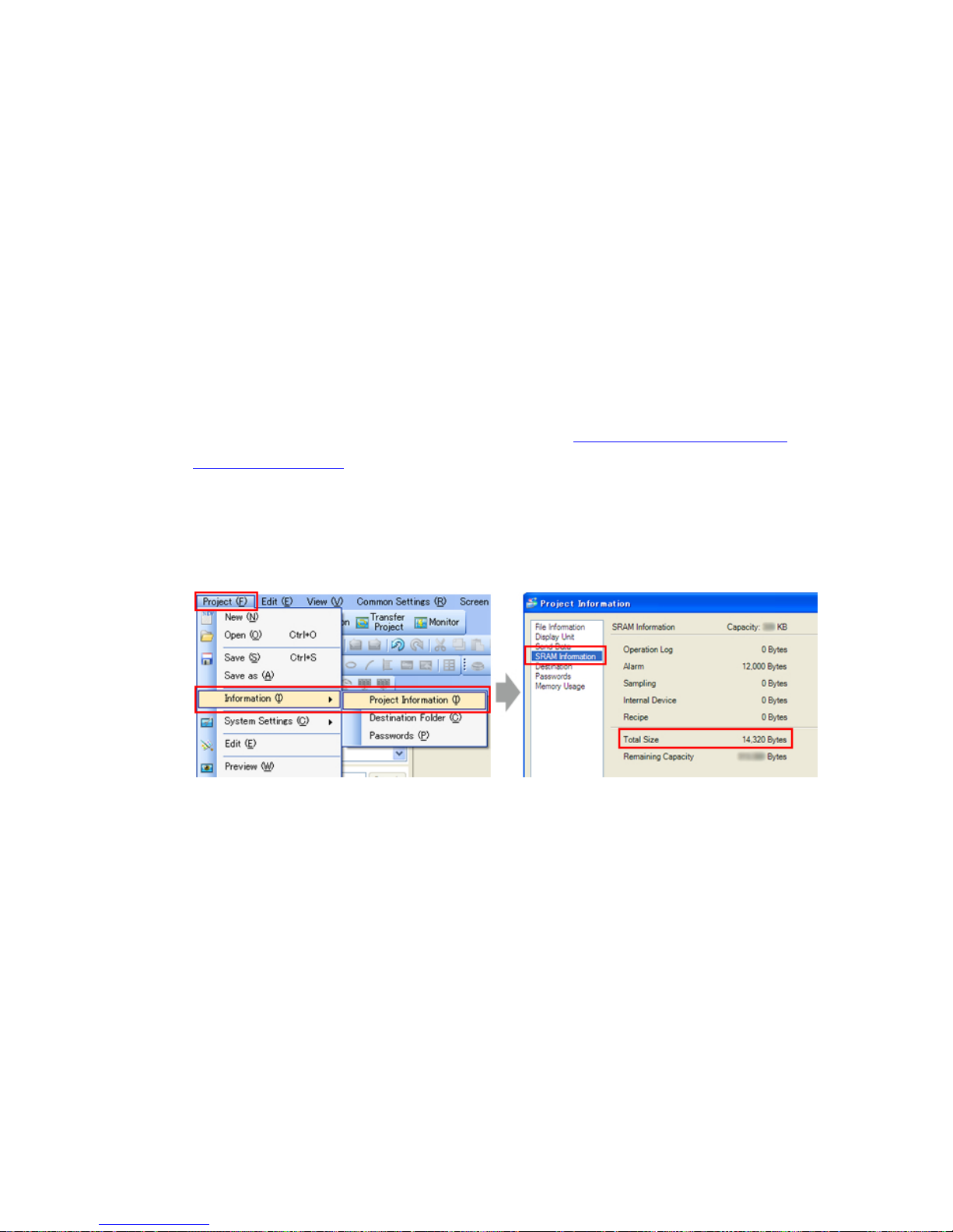
To check SRAM size, follow the steps below;
(1) Convert GP-2300L project file (*prw) to GP-Pro EX’s project file (*.prx).
To know how to convert a project file (*.prw), see [3.4 Convert screen data with
the Project Converter].
(2) Double click and open the converted project file (*.prx) on GP-Pro EX.
(3) Click [Project]->[Information]->[Project Information]. The Project Information
window appears.
(4) Click [SRAM In formation] to see SRAM size.
24/59
Page 25
Chapter 3 Replacement Procedure
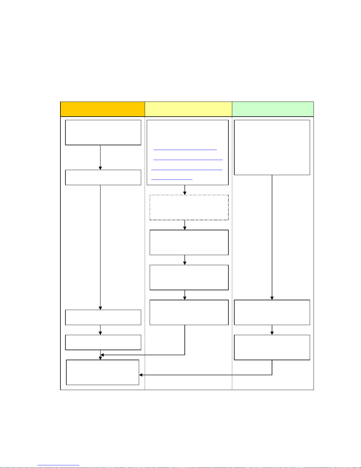
3.1 Work Flow
Receive screen data from
GP-2300 series. *1
Convert GP-2300 series
screen data with GP-Pro
EX’s Project Converter.
Check and modify the data
on GP-Pro EX.
Transfer the screen data to
GP-4301T/TW.
Connect GP-4301T/TW
and PLC with the PLC’s
Start connection and check
the communication.
Remove GP-2300 series.
Connect the power cord.
Check the performance
and start operation.
Installation Screen
Check the compatibility of
hardware in Chapter 2.
Check the differences of
specifications in OtasukePro!
[Compatibility of Software]
(http://www.pro-face.com/o
tasuke/qa/gp3000/replace/s
oft/conv/care/3/).
Check the connection
between GP-4301T/TW
and a PLC in the GP-Pro EX
Device/PLC Connection
Manual.
Install GP-4301T/TW.
Communication
*1: This step is required if screen data is saved only in the GP unit, not in any other device.
25/59
Page 26

3.2 Preparation
Requirements for
receiving screen data
from GP-2300 series.
*1
GP-2300T/2300L/2301S/2301L:
PC in which GP-PRO/PBIII for Windows V6.0 or later is
installed. *2
GP-2300S/2301T:
PC in which GP-PRO/PBIII for Windows C-Package02 V6.3 or
later is installed. *2
Transfer Cable
(The following three types of cables are available.)
・ GPW-CB02 (D-sub 9 pin to PC)
・ GPW-CB03 (USB to PC) *3
・ GP430-CU02-M or GPW-SET (D-sub 25 pin to PC)
* Possible to send/receive a screen via Ethernet (for
GP-2300T/S/L only) or with a CF card.
Requirements for
converting screen
data of GP-2300
series and
transferring the
converted data to
GP-4301T/TW
PC in which GP-Pro EX Ver.3.0 or later is installed
Transfer Cable
(The following three types of cables are available.)
・ A USB transfer cable (model: CA3-USBCB-01)
・ A USB data-transfer cable (model: ZC9USCBMB1)
・ A commercial USB cable (USB Type A/mini B)
* Possible to send/receive a screen with a SD card
(GP-4301TW only), a USB storage device or via Ethernet.
*1: This step is required if screen data is saved only in the GP unit, not in any other device
*2: Please use the same version or later as or than that of the software used during creating screens on
GP-2300 series. If you don’t know the version, we recommend you to use the newest version. The
newest version is GP-PRO/PBIII for Windows C-Package03 (SP2) V7.29. Those who have
GP-PRO/PBIII for Windows C-Package03 V7.0 can download it from our web site called [OtasukePro!]
(http://www.pro-face.com/otasuke/download/update/
).
*3: GPW-CB03 is supported by GP-PRO/PBIII for Windows C-Package02 (SP2) V6.23 or later. You need to
install a driver from [Download] on our Web site called [OtasukePro!]
(http://www.pro-face.com/otasuke/download/driver
).
26/59
Page 27
3.3 Receive screen data from GP-2300 series
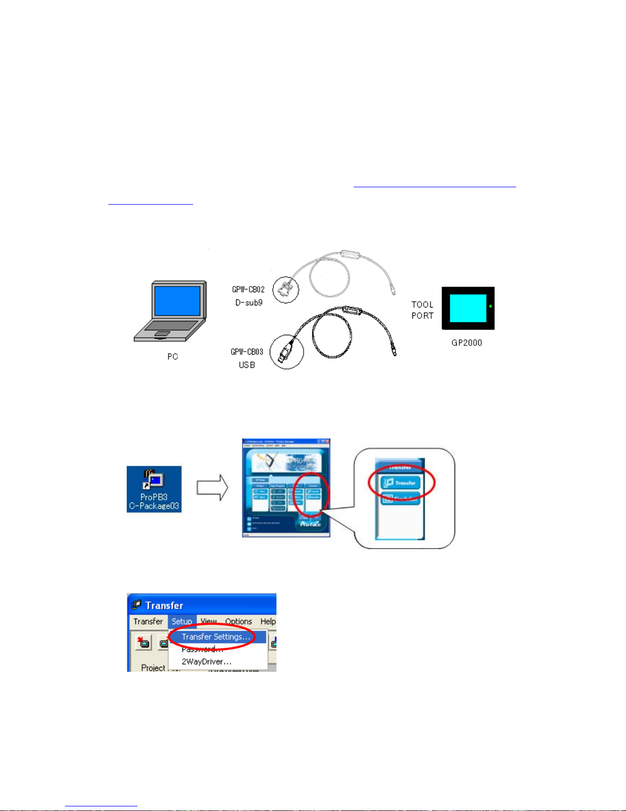
This section explains, as an example, how to receive screen data from GP-2300 series
using a transfer cable, GPW-CB02 or GPW -CB03. If you have back ed up screen data,
this step is unnecessary; skip to the next section [3.4 Convert screen data with the
Project Converter].
(1) Connect a transfer cable to the GP-2300 series.
(2) Strat up GP-PRO/PBIII for Windows and click the [Transfer] icon on the Project
Manager (Specify a desired project file.)
(3) On the [Transfer] window, select the [Setup] menu and click [Transfer Settings.]
27/59
Page 28
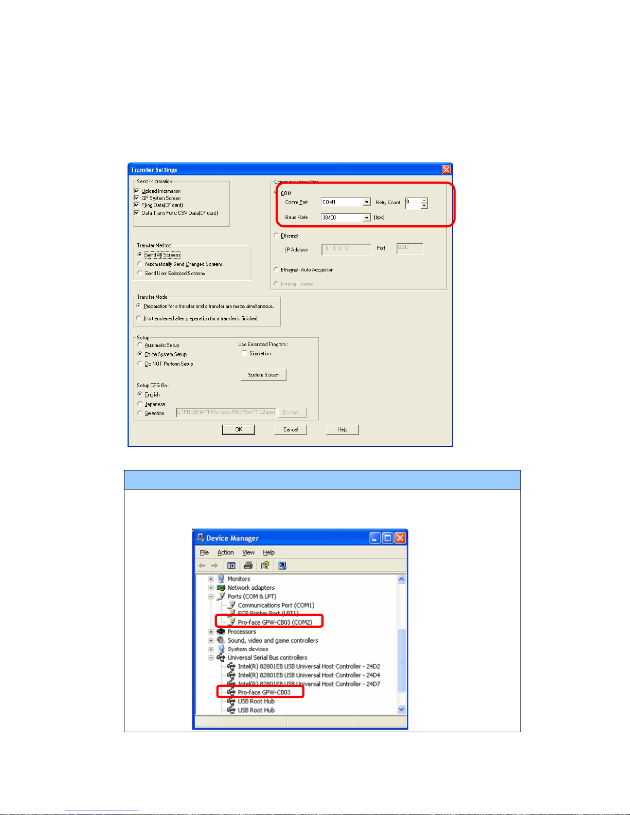
(4) In the Communication Port field, select [COM], specify the COM port to which the
cable is connected, and click [OK].
If you use a USB transfer cable (GPW-CB03)
You can check the COM port for the USB transfer cable (GPW-CB03), which is
assigned to the PC, with the Device Manager of Windows.
28/59
Page 29
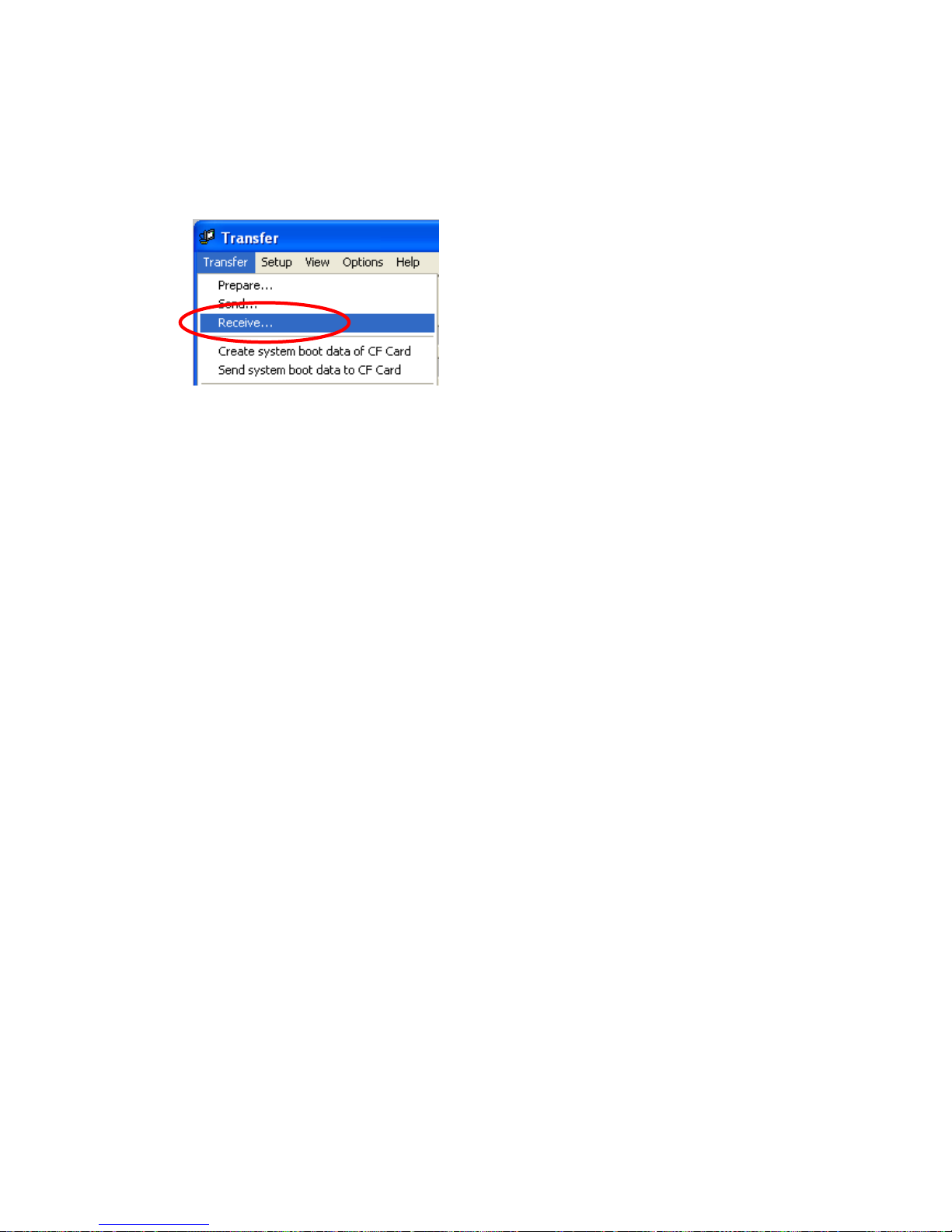
(5) Select the [Transfer] menu and click [Receive...].
(6) Specify the location to save the received screen data at and the project file name
and save them.
29/59
Page 30
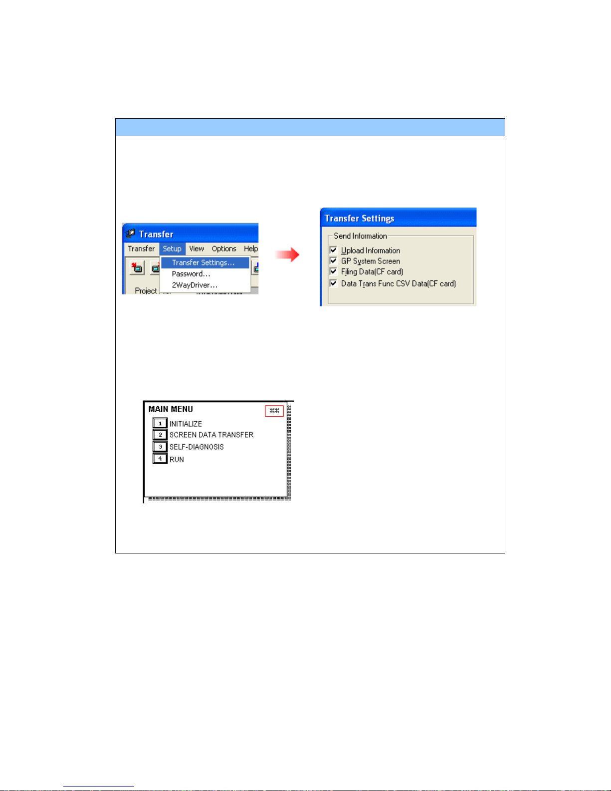
In case there is no Upload Information
“Upload Information” is necessary to receive screen data from GP-2300 series. It
needs to be included in screen data when transferring screen data to the display
unit beforehand. The Upload Information is sent to the display unit by default,
however, you may check off the box of Upload Information to preven t screen
reception by a third party.
You ca n check in the following wa y if the Upload Information has been sent or not.
1. Enter into the GP’s Offline mode.
2. If there are 2 asterisk (*) marks in the Main menu as shown below, the
Upload Information has been sent.
If not, there is no “Upload Information” sent. In this case, a message, which
indicates there is no “Upload Information”, appears and you cannot receive the
data.
30/59
Page 31
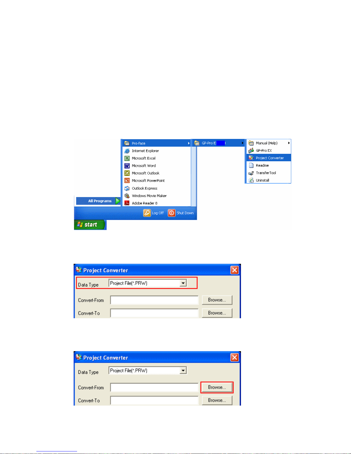
3.4 Convert screen data with the Project Converter
Convert a project file (*.prw) for GP-2300 series with the GP-Pro EX’s Project
Converter.
(1) Click the [Start] button, select [All Programs] (or [Programs])->[Pro-face]->
[GP-Pro EX *.**]->[Project Converter]
(For the [*.**] part, the version of the software you use is displayed.)
(2) The Project Converter starts up and the [Project Converter] dialog box opens.
Select [Project File (*.PRW)] in the [Data Type].
(3) Click the [Browse…] button and select a project file (e.g.: “Project system A.prw”).
Click [Open], and the file will be set in [Convert-From].
31/59
Page 32
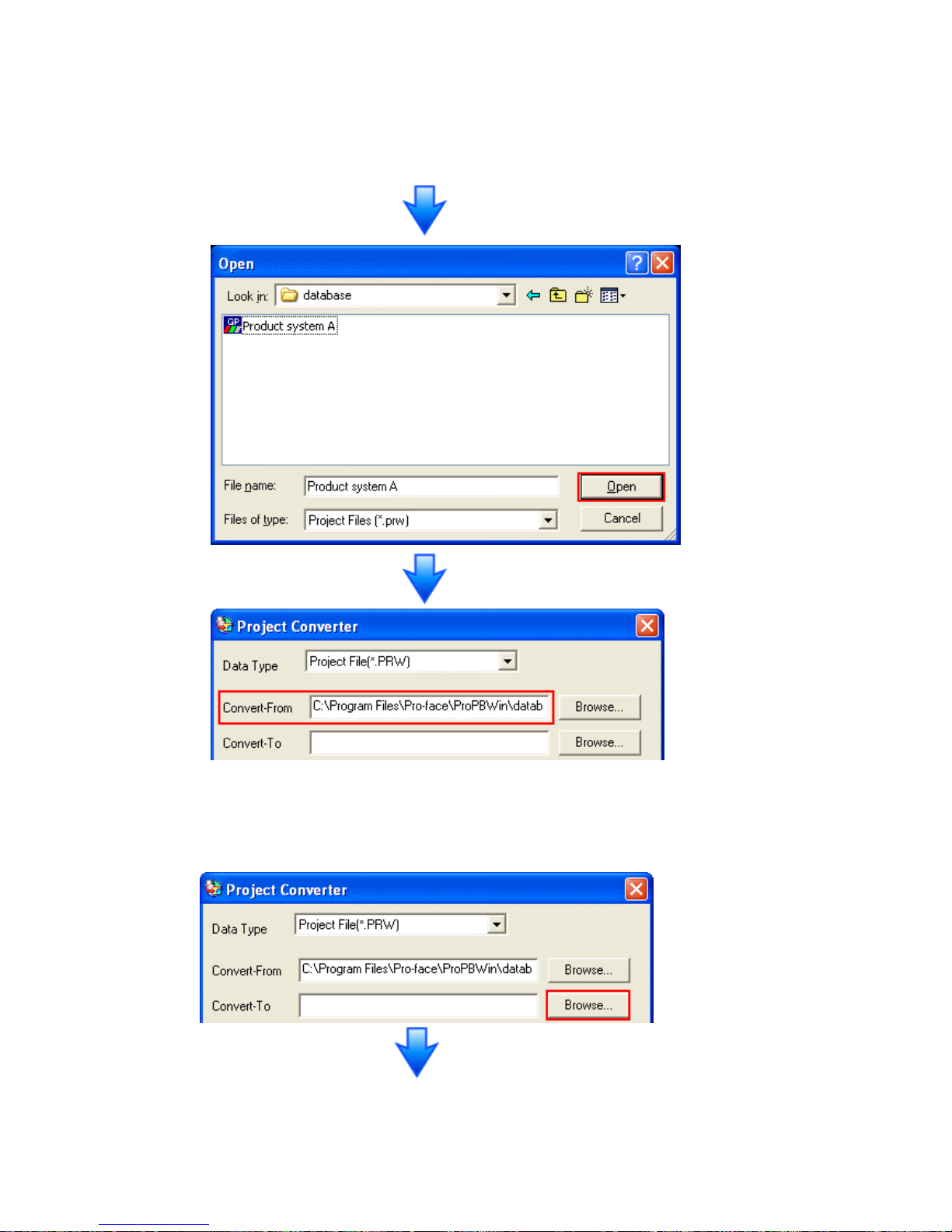
(4) In [Convert-T o], designate a GP-Pro EX’ s project file (*.prx). Click the [Browse…]
button and enter a new [File Name] (e.g.: “Product system A.prx”). Cl ick [Save],
and a new project file will be set to [Convert-To].
32/59
Page 33
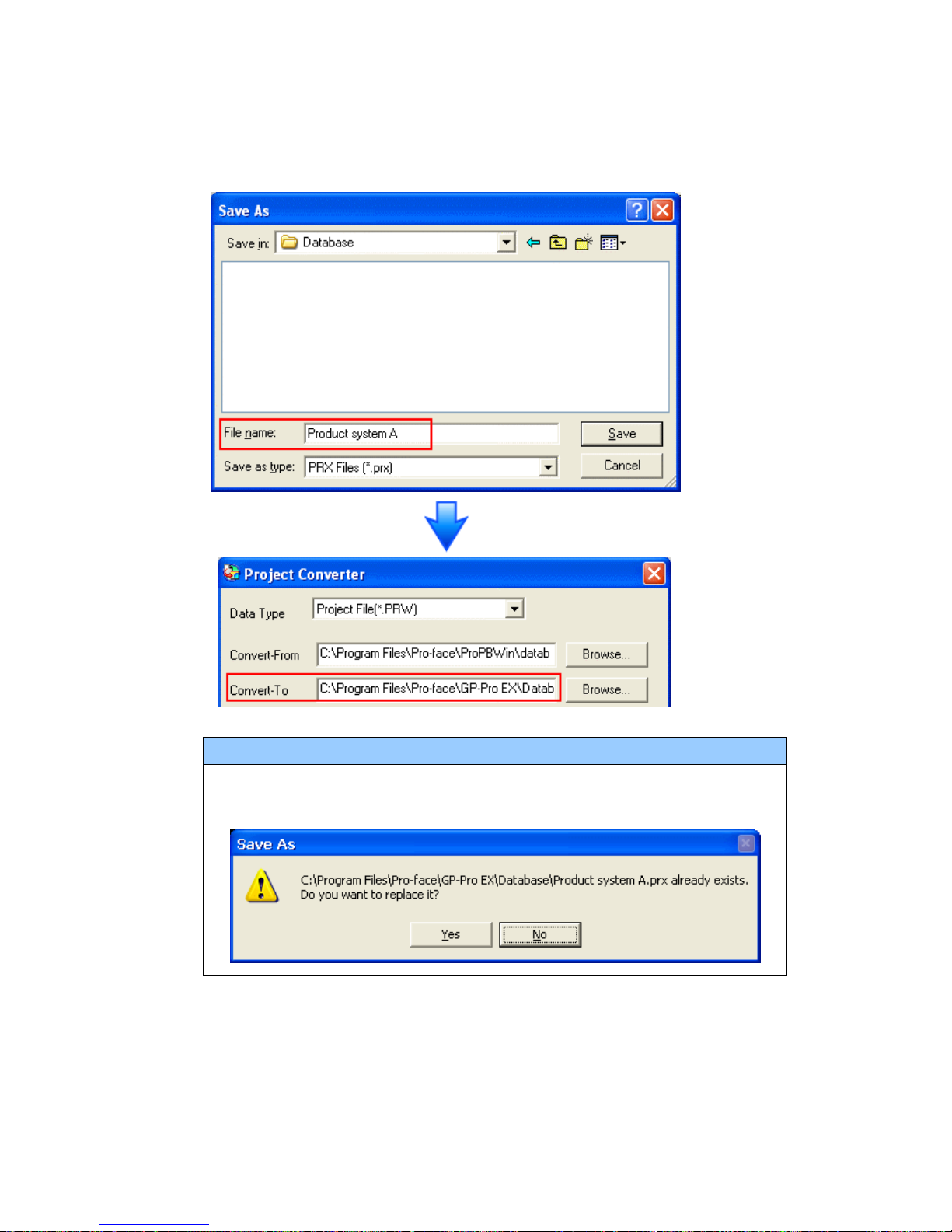
NOTE
When a convert-to file exists, the window that confirms whether or not to
overwrite the file is displayed.
33/59
Page 34
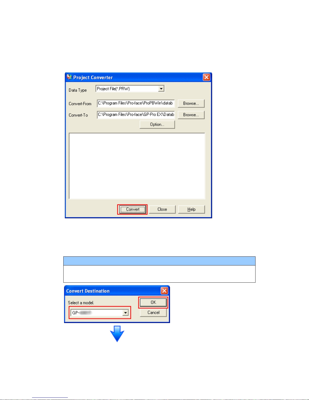
(5) Click [Convert] and start the conversion.
(6) If you are asked about the [Convert-To] type as shown below, select a
replacement model’s name on the pull-down menu. Click [OK].
NOTE
When replacing GP-2300L with GP-4301TW, select [GP-4301T] on the
pull-down menu.
34/59
Page 35
If an error message is displayed during conversion…
If an error message is displayed during conversion, refer to [Project Converter
Error Message]
(http://www.pro-face.com/otasuke/qa/gp3000/replace/soft/conv/project_con
verter_error.html) on our Web site called [OtasukePro!] for the cause and the
solution.
NOTE
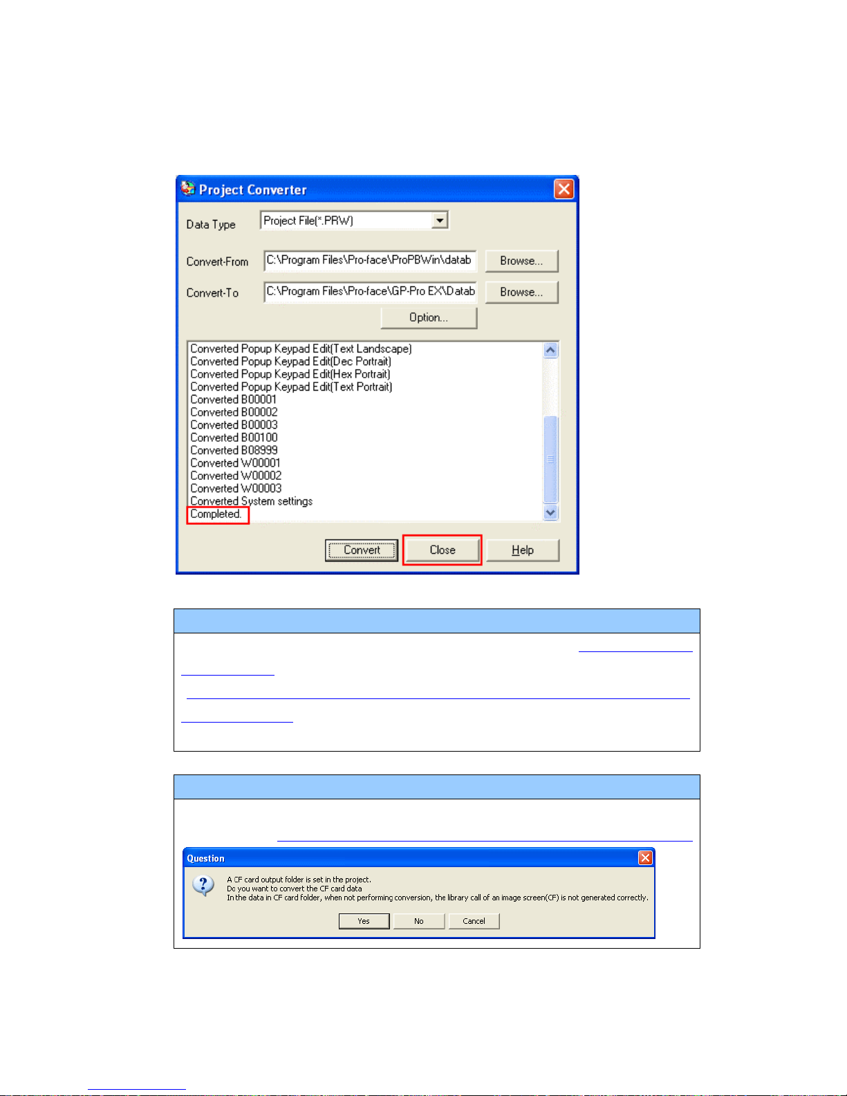
If the following dialog box appears, CF Card Ouput Folder setting is required.
Please refer to Convert GP-PRO/PBIII for Windows’”Destination CF Card Folder”
35/59
Page 36
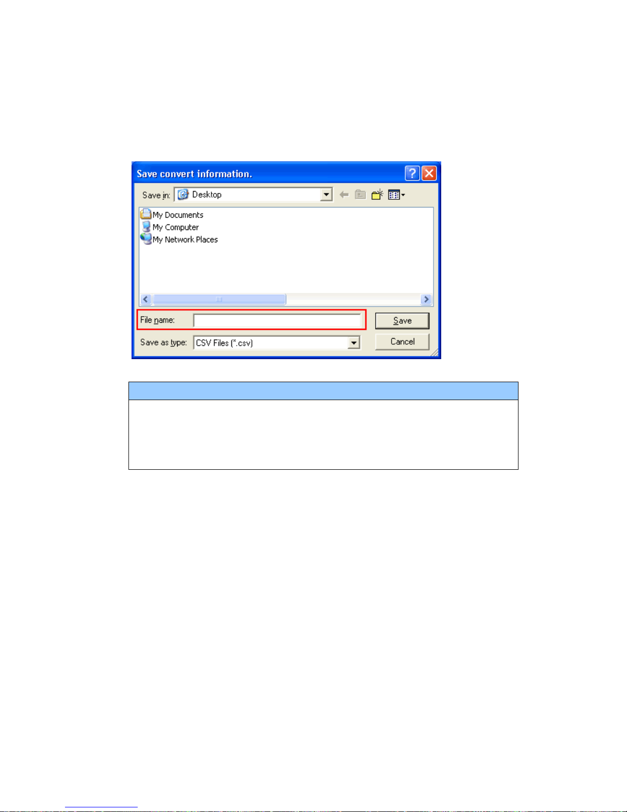
(7) After conversion, the [Save convert information] dialog bo x appears. If you click
[Save], you can save the conversion information in a CSV file format.
NOTE
Because the differences made at the time of conversion from GP-Pro/PBIII for
Windows are described in the CSV saved file, the project file (*.prx) after
conversion can be checked and modified according to the conversion
information.
(8) Click [Close] to close the [Project Converter] dialog box.
If you double click the project file (*.prx) after conversion, GP- Pro EX will start and
the file will open.
36/59
Page 37
IMPORTANT
When the settings for the both COM1 and COM2 ports are configured for
GP-2300T/S/L, the settings for the COM2 port are not converted on GP-Pro EX. If
you still need the settings of the COM2 port for GP-2300T/S/L, add Device/PLC
setting from [System Settings] on the [Project] menu of GP-Pro EX.
Convert GP-PRO/PBIII for Windows “Destination CF Card Folder”
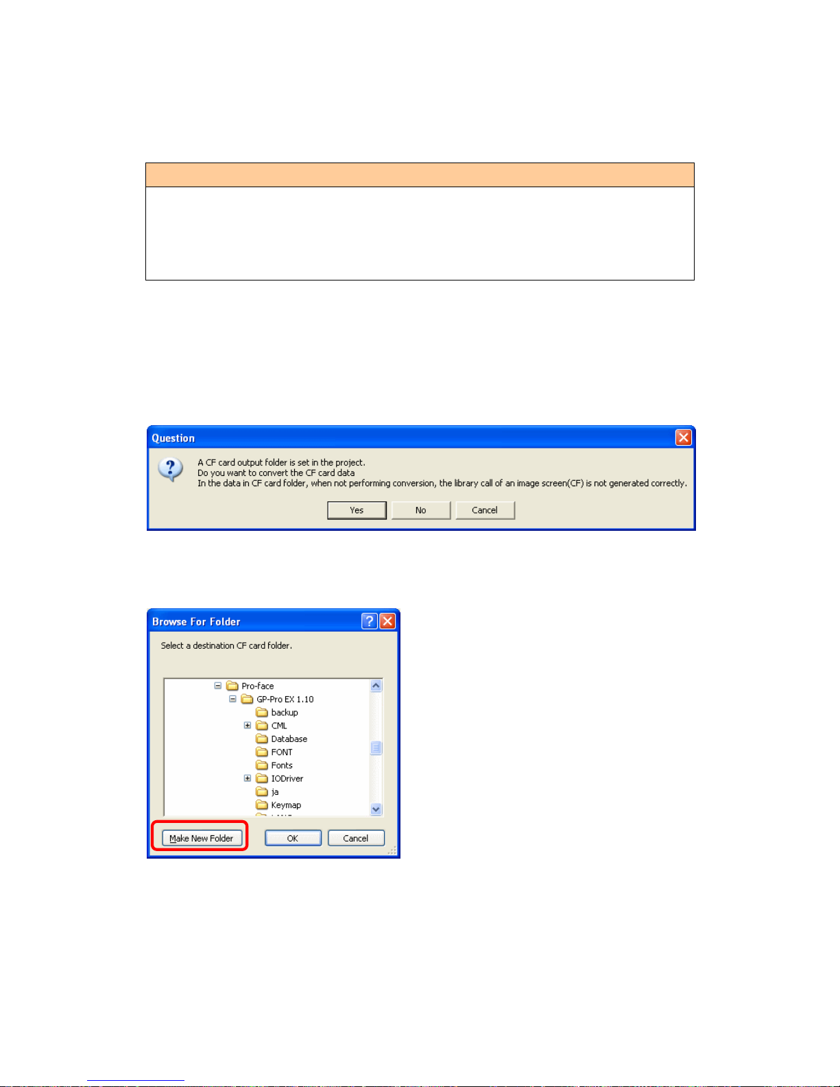
If you convert a project file (*.prw) with a destination CF card folder designated in the
step 6, the Question dialog box asking whether or not to designate the destination CF
card folder for the convert destination appears again.
Select a folder (e.g.: “Database”) and click [OK].
If you click the [Make New F older] button, you can create a new folder at an y location.
37/59
Page 38

IMPORTANT
・ In the [Question] dialog box, be sure to select [Yes] and specify the destination
folder. If you select [No], images will not be called correctly.
・ GP-4301T/TW that is a replacement model is not equipped with a CF card slot.
If a destination folder is created in the work above, the CF card setting will be
replaced with the SD card setting automatically.
T o check or change the destination folder setting, see [5.1 Changing the setting
of the external media to use].
3.5 Change the Display Unit Type
(* Only when replacing GP-2300L with GP-4301TW)
Open the project file (*.prx) on GP-Pro EX that is converted in the Chapter 3.4 and
change the display unit type to GP-4301TW.
(1) Open the converted project file (*.prx) on GP-Pro EX.
(2) Click [System Settings]->[Display]->[Change Display] in [Project] menu and
change the Display Unit type to “GP-4301TW”.
(3) Click [Project]->[Save] or [Save As] to save the change.
38/59
Page 39
3.6 Transfer screen data to GP-4301T/TW
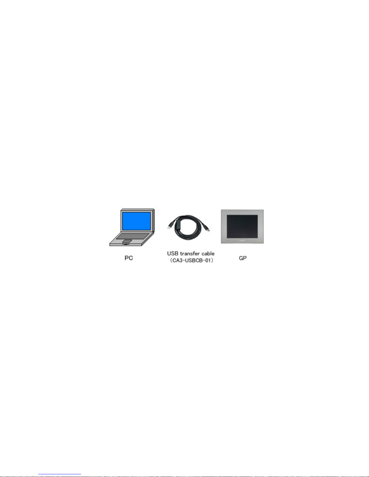
Transfer the project file after conversion to GP-4301T/TW.
You can transfer data to GP-4301T/TW via;
・ An USB transfer cable (model: CA3-USBCB-01)
・ An USB data transfer cable (model: ZC9USCBMB1)
・ A commercial USB cable (USB Type A/mini B)
・ A SD card (for GP-4301T only) /USB storage device
・ Ethernet
But this section explains, as an example, how to transfer screen data with an USB
transfer cable (model: CA3-USBCB-01).
39/59
Page 40
(1) Connect your PC and GP-4301T/TW with an USB transfer cable (model:
CA3-USBCB-01). If the driver of the cable has not been installed on you PC yet, a
dialog box will appear. Please follow the instructions.
NOTE
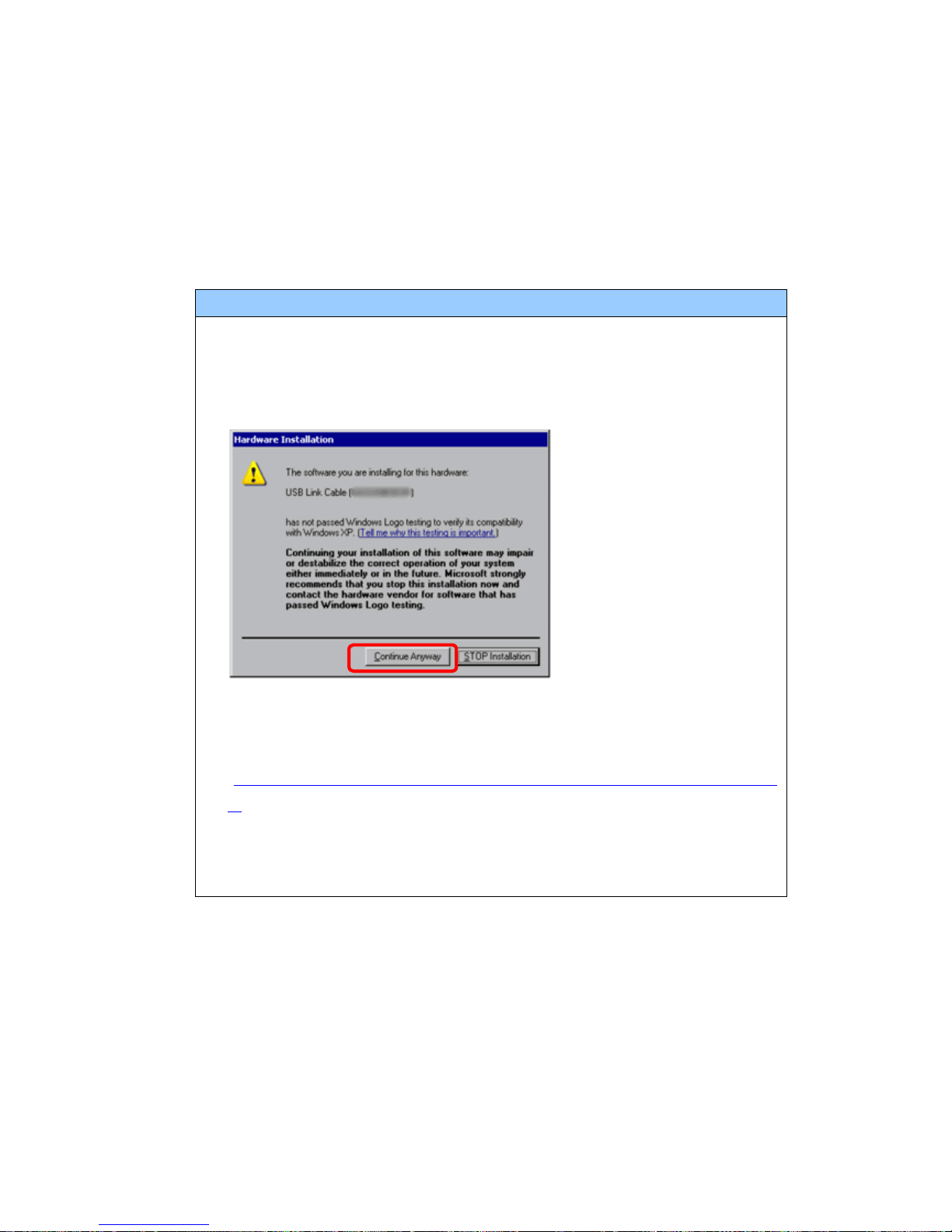
・ The “Hardware Installation” dialog box as shown below may appear during
installing the USB driver depending on the security level o f Windows® XP.
Click [Continue Anyway] to start install ing the driver. When installation is
completed, click [Finish].
・ If the following symptoms appear on Microsoft Windows® 7, go to upda ting
“USB Data Transfer Driver” on [ OtasukePro!] for download
(http://www.pro-face.com/otasuke/download/freesoft/gpproex_transfer.ht
m).
- An error occurs when GP-Pro EX or Transfer Tool is installed
- An error occurs when data is transferred via a USB transfer cable
(model: CA3-USBCB-01).
40/59
Page 41
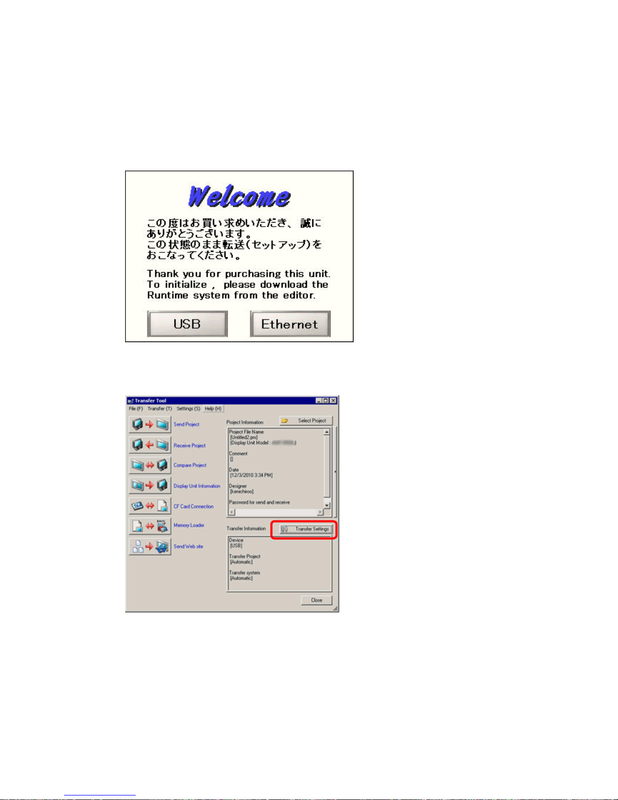
(2) T urn on the power of G P-4301T/TW. The “Initial Start Mode” screen will appear on
the display unit. After transferring a project file once, this screen will not appear
again.
(3) On the GP-Pro EX’s State Toolbar, click the [Transfer Project] icon to open the
Transfer Tool.
To transfer a different project file, click the [Select Project] button and select a
project file.
41/59
Page 42
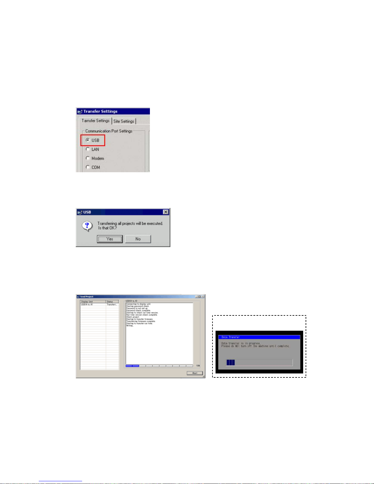
(4) Make sure that the [Device] in the “T ransfer Settings Information” is set to [USB].
If not, click the [T rans fer Setting] button to open the “T r ansfer Setting” dialog box.
Select [USB] in the Communication Port Settings field and click [OK].
(5) Click [Send Project] to start transfer. When the following dialog box appears, click
[Yes]. This dialog box doesn’t appear when the same project file is sent again.
(6) The following dialog box appears during transfer and you can check the
communication status. (The display unit enters the Transferring mode and
communication with the device such as a PLC is terminated.)
Display Screen
42/59
Page 43
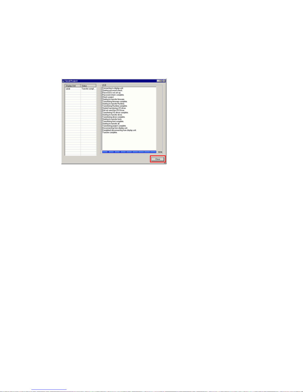
(7) When transfer is completed, the status displayed in the dialog box will change
from [Transferring] to [Complete Transfer]. Click [Close] to close the dialog box.
The display unit will be reset and a screen of the transferred project file will be
displayed.
(8) Close the Transfer Tool.
(9) Click the [X] mark on top right of the screen or [Project]->[Exit] to close GP-Pro
EX.
43/59
Page 44
3.7 Differences of software
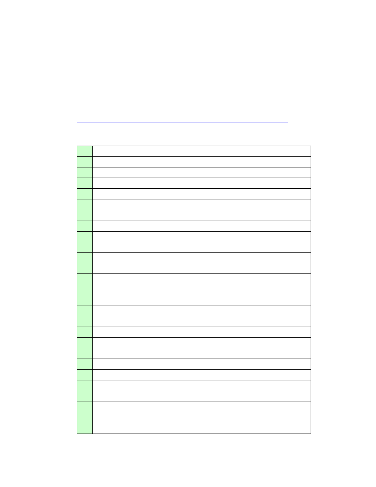
3.7.1 Differences after conversion
Check the differences of screen data after conversion from GP-PRO/PBIII to
GP-Pro EX. For the details of each item, refer to our website,
http://www.pro-face.com/otasuke/qa/gp3000/replace/soft/conv/care/3/
Differences of Software
1 Touch Panel Type
2 Compatibility of Bit Switch
3 Compatibility of Alarm
4 Compatibility of Trend Graph
5 Compatibility of K tag (Input Order)
6 Compatibility of K tag (difference of Writing)
7 Compatibility of K tag (Indirect Setting)
8 Compatibility of N tag
9 Precautions for using the switch for [History Data Display] of T rend Graph
on the window
10 About window display on a momentary switch during momentary
operation
11 About the performance when a display area of the system window is
overlapping
12 Change of Tag Process
13 About the display when a fixed Draw is placed on a Part
14 Compatibility of Text
15 Compatibility of Fill
16 Compatibility of CF Card Data
17 Precautions for conversion when filing data is saved in a CF card
18 Precautions for setting “Color Settings” to [256 Colors without blinking]
19 Precautions for loading a part with “L Tag (Library Display)”
20 Compatibility of MRK files and CPW files
21 Compatibility of V Tag/v tag and Video Screen
22 Compatibility of Extended SIO Script
23 Compatibility of Sound Data
24 Compatibility of Device Monitor
44/59
Page 45

25 Compatibility of Ladder Monitor
26 Compatibility of J Tag and R Tag
27 Converting Screen Data of DOS
28 Compatibility of Standard Font
29 D Script starts right after screen change or power on.
(Compatibility of D Script Trigger Condition)
30 The position shifts when loading a window screen (Compatibility of U T a g)
31 Precautions for using Screen Level Change
32 Compatibility of H tag
45/59
Page 46
Chapter 4 Communication with Device/PLC
4.1 Drivers
More connectable drivers will be added.
For the devices/PLC each driver supports, see [Connectable Devices]
(http://www.pro-face.com/product/soft/gpproex/driver/driver.html
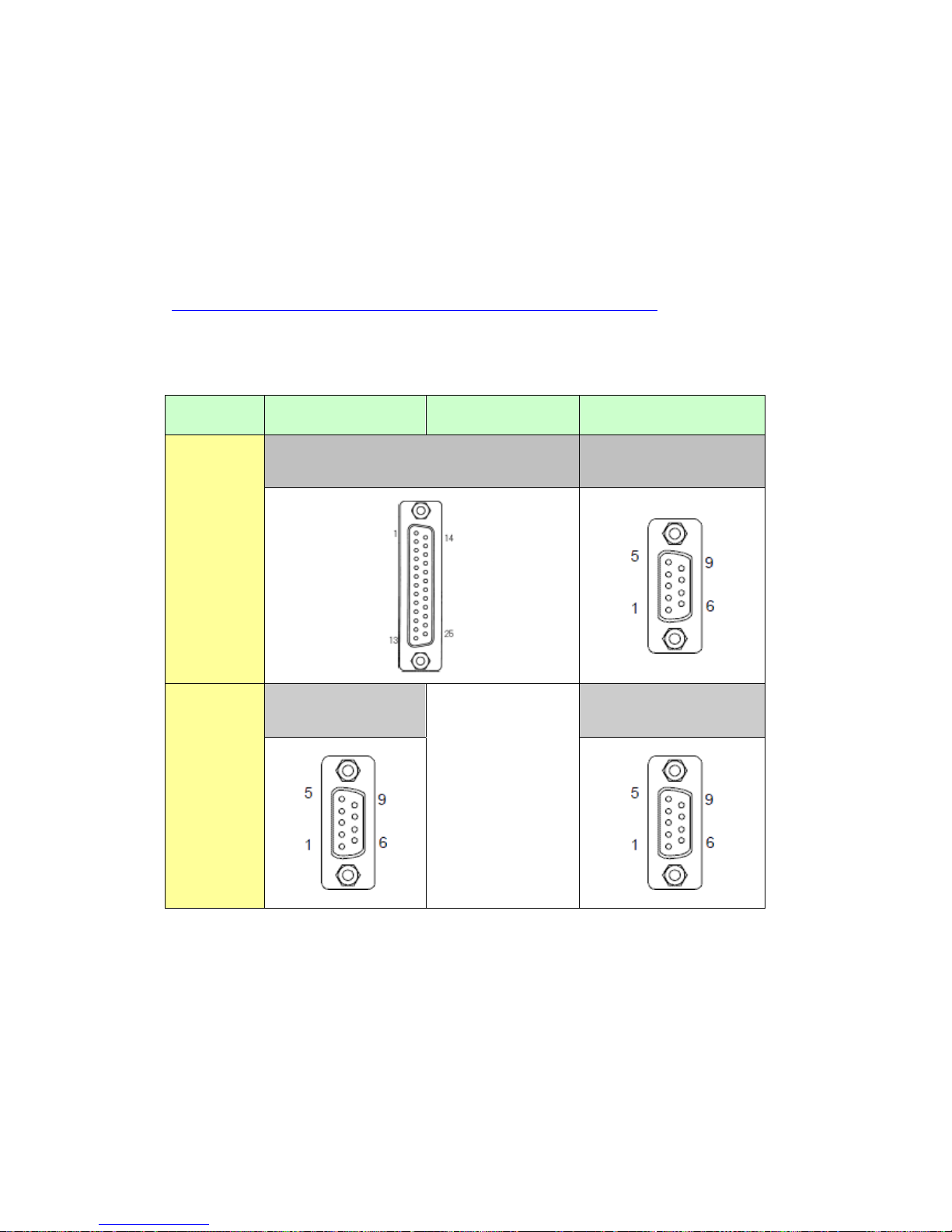
).
4.2 Shapes of COM ports
GP-2300T/S/L GP-2301T/S/L GP-4301T/TW
COM1
D-Sub 25 pin (socket)
RS-232C/422
D-Sub 9 pin (plug)
RS-232C
COM2
D-Sub 9 pin (plug)
RS-232C
-
D-Sub 9 pin (plug)
RS-422/485
46/59
Page 47
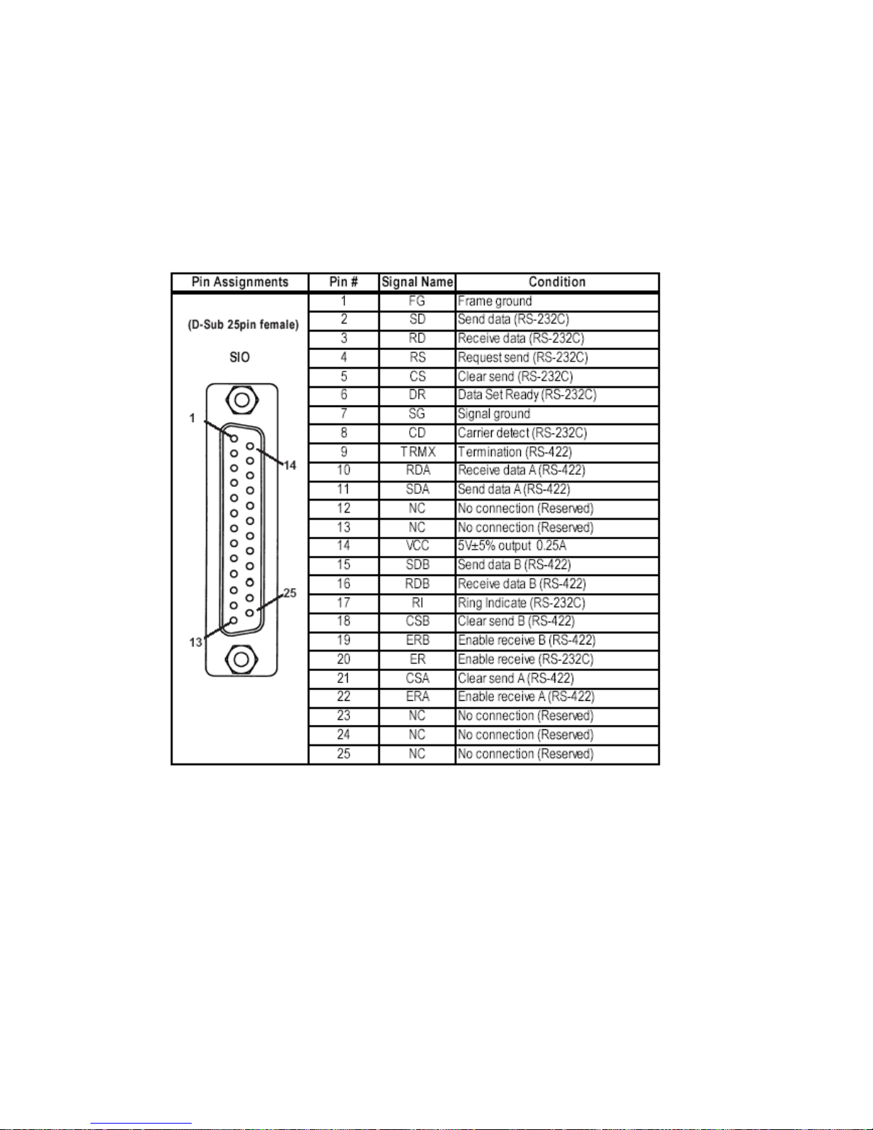
4.3 Signals of COM ports
4.3.1 Signals of COM1
For GP-2300 series
RS-232C or RS-422 (socket)
47/59
Page 48
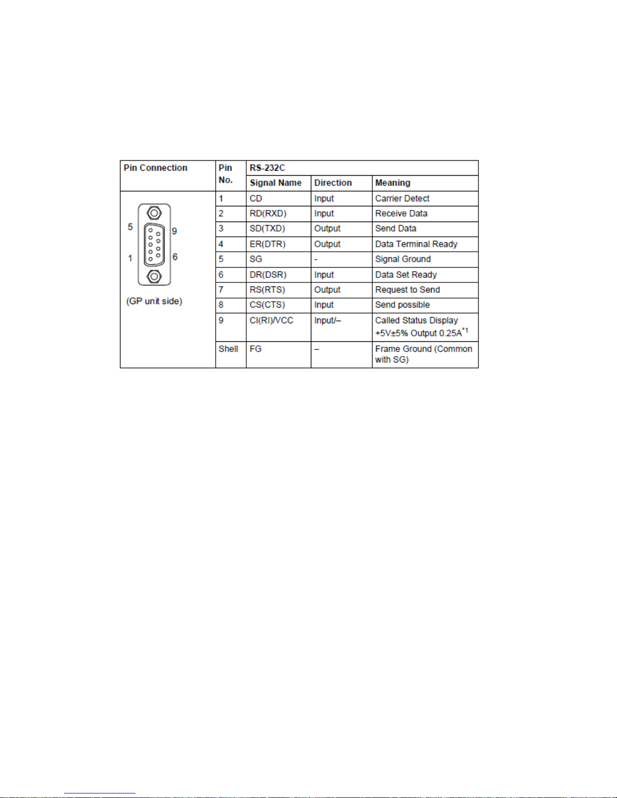
For GP-4301T/TW
RS-232C (plug)
*1: RI and VICC of Pin 9 are switched on the software.
VCC Output is not protected from overcurrent.
Please follow the current rating to avoid false operation or breakdown.
48/59
Page 49
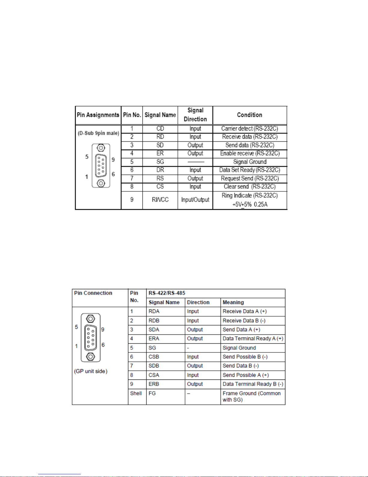
4.3.2 Signals of COM2
For GP-2300T/S/L
RS-232C (plug)
For GP-2301T/S/L
N/A
For GP-4301T/TW
RS-422/485 (plug)
49/59
Page 50
4.4 Multilink Connection
For GP-4301T/TW, some communication drivers do not support multi-link connection
(n:1) via RS-422.
When converting the project file with the setting of the communication driver that
does not support multi-link connection (n:1) via RS-422, the connection is
automatically converted to (1:1).
For the communication drivers that support serial multi-link, see [Which drivers
support serial multilink communication?]
(http://www.pro-face.com/otasuke/files/manual/gpproex/new/device/com_mlnk.ht
m).
4.5 Internal 2-Port feature for Mitsubishi PLC
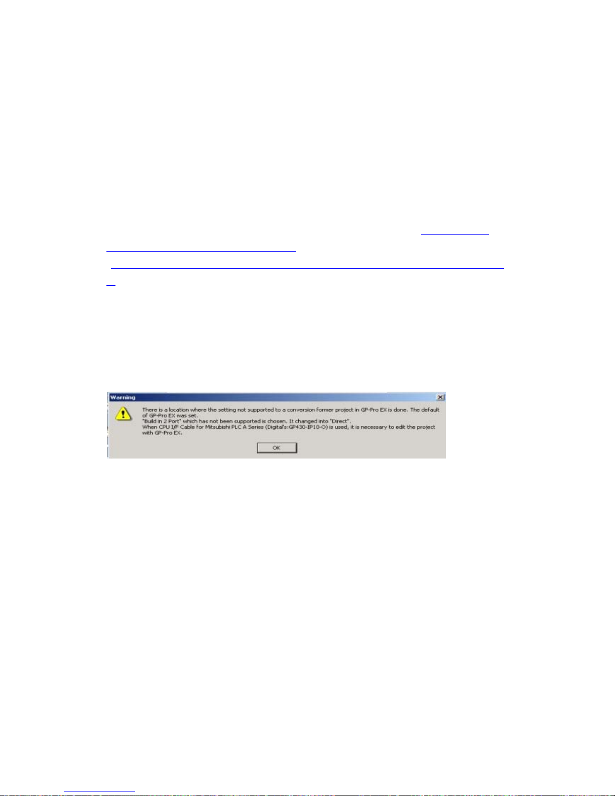
For GP-4501TW, the internal 2-Port feature for Mitsubishi PLC cannot be used.
If [GP Setup]->[Mode Settings]->[Option]->[Inernal 2 port] is selected on
GP-PRO/PBIII, the following message will appear when converting the project file with
the GP-Pro EX Project Converter.
50/59
Page 51
4.6 Cable Diagram at the time of replacement
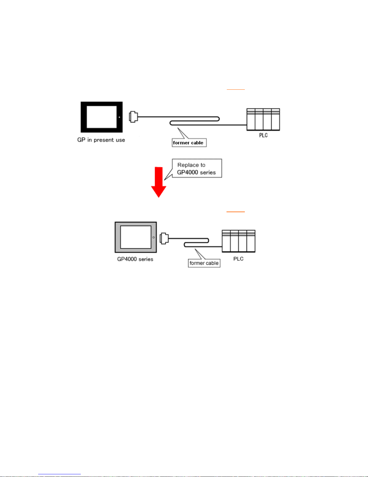
The connection cable for GP-2300 series can be used for GP-4301T/TW.
But please note that there are precautions and restrictions as described below.
IMPORTANT
・ Please check the connection configurations GP-4301T/TW supports with GP-Pro
EX Device/PLC Connection Manual before using a connection cable.
(http://www.pro-face.com/otasuke/files/manual/gpproex/new/device/index.ht
m)
・ The Siemens MPI connection cable cannot be used.
Please refer to the above-mentioned GP-Pro EX Device/PLC Connection Manual
and prepare a connection cable for GP-4301T/TW newly.
51/59
Page 52
4.6.1 When using a RS-232C connection cable
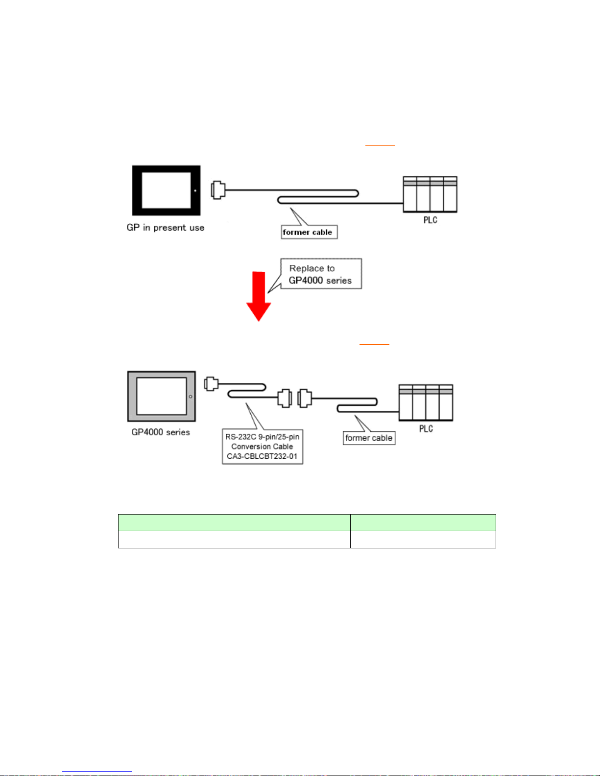
GP-2300 series System Configuration (connecting to COM1
)
GP-4301T/TW System Configuration (connecting to COM1
)
To replace GP-2300 series with GP-4301T/TW, prepare the following item.
Product Name Model
RS-232C 9-pin/25-pin Conversion Cable (20cm)
CA3-CBLCBT232-01
52/59
Page 53
When using CPU I/F Cable for Mitsubishi PLC…
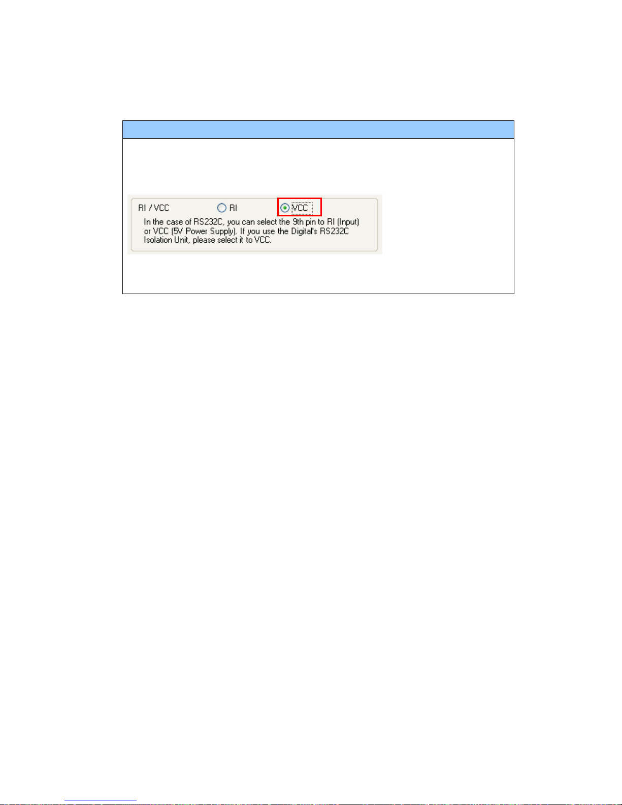
When using CPU I/F Cables for Mitsubishi PLC (GP430-IP10-O/ GP430-IP11-O)
with GP-2300 series, be sure to select “VCC” in the Device/PLC Setting on GP-Pro
EX after converting a project file, or the communication will not work properly.
T o change this setting, select [System Settings] -> [Device/PLC] in the [Project]
menu on GP-Pro EX.
53/59
Page 54
* For GP-2300T/S/L only:
GP-2300T/S/L System Configuration (connecting to COM2
)
GP-4301T/TW System Configuration (connecting to COM1
)
*The same cable can be used.
54/59
Page 55
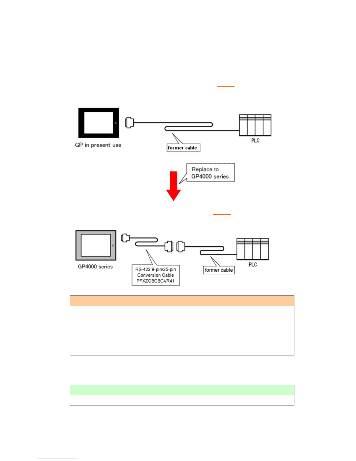
4.6.2 When using a RS-422 connection cable
GP-2300 series System Configuration (connecting to COM1
)
GP-4301T/TW System Configuration (connecting to COM2
)
IMPORTANT
Before connecting to GP-4301T/TW, be sure to change the port setting to
[COM2] on Device/PLC Setting of GP-Pro EX. Please check the communication
setting with GP-Pro EX Device/PLC Connection Manual just in case.
(http://www.pro-face.com/otasuke/files/manual/gpproex/new/device/index.ht
m)
To replace GP-2300 series with GP-4301T/TW, prepare the following item.
Product Name Model
RS-422 9-pin/25-pin Conversion Cable (20cm) PFXZCBCBCVR41
55/59
Page 56
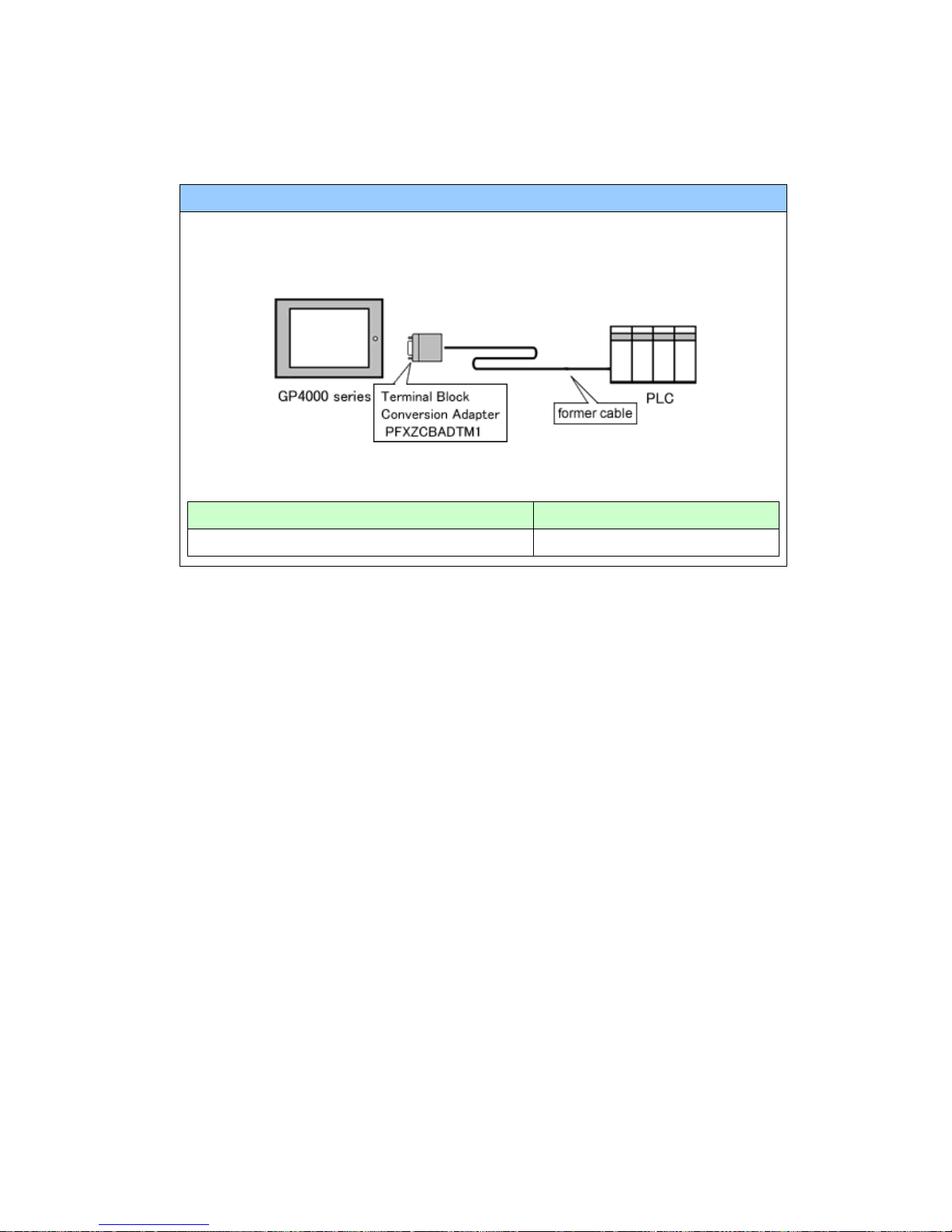
NOTE
When using a terminal block adapter (GP070-CN10-O), we recommend you to
replace it with a terminal block conversion adapter (PFXZCBADTM1) for
GP-4301T/TW.
For replacement in this connection method, prepare the following item.
Product Name Model
Terminal Block Conversion Adapter PFXZCBADTM1
56/59
Page 57
Chapter 5 Appendix
5.1 Changing the setting of the external media to us e
If a CF card has been used for GP-PRO/PBIII, after GP-2300 series is replaced with
GP-4301T/TW with GP-Pro EX, “a CF card” is automatically replaced with “a SD card”
for the external media setting.
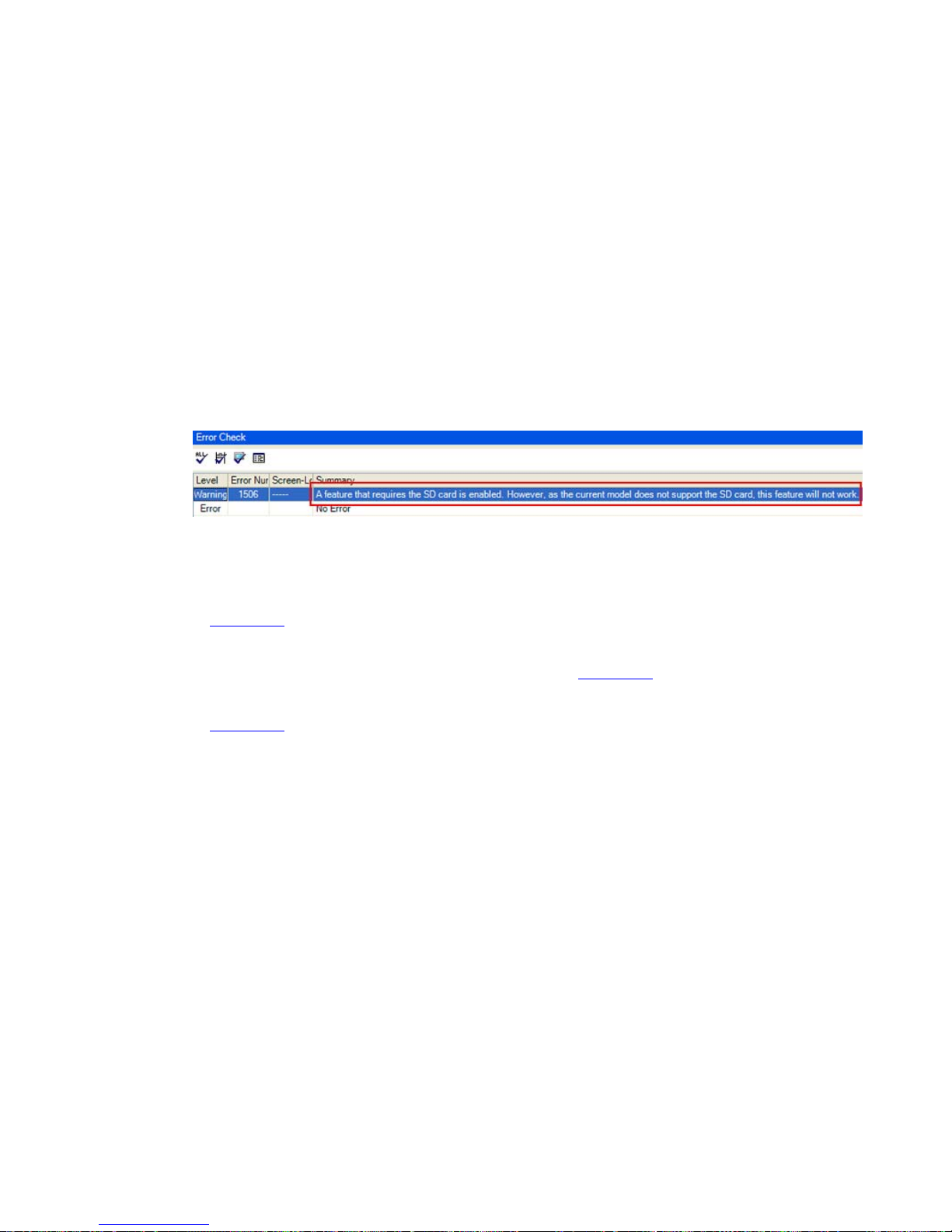
(1) After conversion of the project file data, at GP-Pro EX Error Check, if the message,
“The project contains features that require a SD card. However, the selected
display does not support SD cards so these features will not run.” appears,
<Cause>
The model without a SD card slot has the setting that uses a SD card.
->Solution 1
(2) To use a USB storage device instead of a SD card ->Solution 1
(3) To check or change the SD card’s data output destination folder setting
->Solution 2
57/59
Page 58
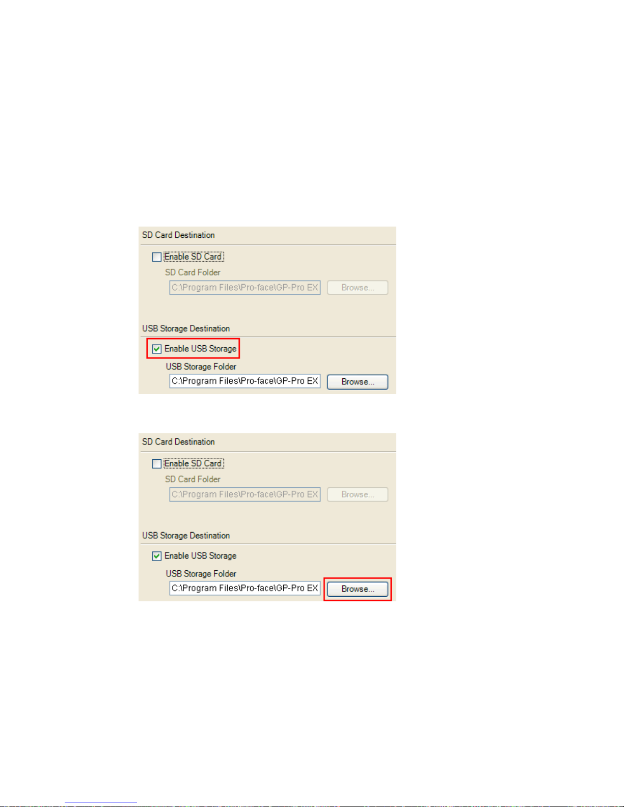
[Solution]
1. Change the SD Card setting to the USB storage setting following the steps below.
<Procedure>
i. Click [Project]->[Information]->[Destination Folder].
ii. Uncheck “Enable SD Card” and check “Enable USB Storage.
iii. Click the [Browse] button and specify a destination folder.
iv. Click [OK] to confirm the setting.
v. Click [Project]->[Save] to save changes.
vi. Check each function that uses the CF card and replace the setting of [SD Card]
with the one of [USB Storage].
58/59
Page 59
NOTE
・ To see how the tags or the parts of GP-PRO/PBIII for Windows are replaced
on GP-Pro EX, refer to [OtasukePro!] (http://www.pro-face.com/
)
“Feature Comparison between GP-PRO/PBIII and GP-Pro EX”
(http://www.pro-face.com/otasuke/qa/gp3000/replace/soft/conv/care/3/co
mpare.htm)
・ To check each function setting of GP-Pro EX, refer to GP-Pro EX Reference
Manual.
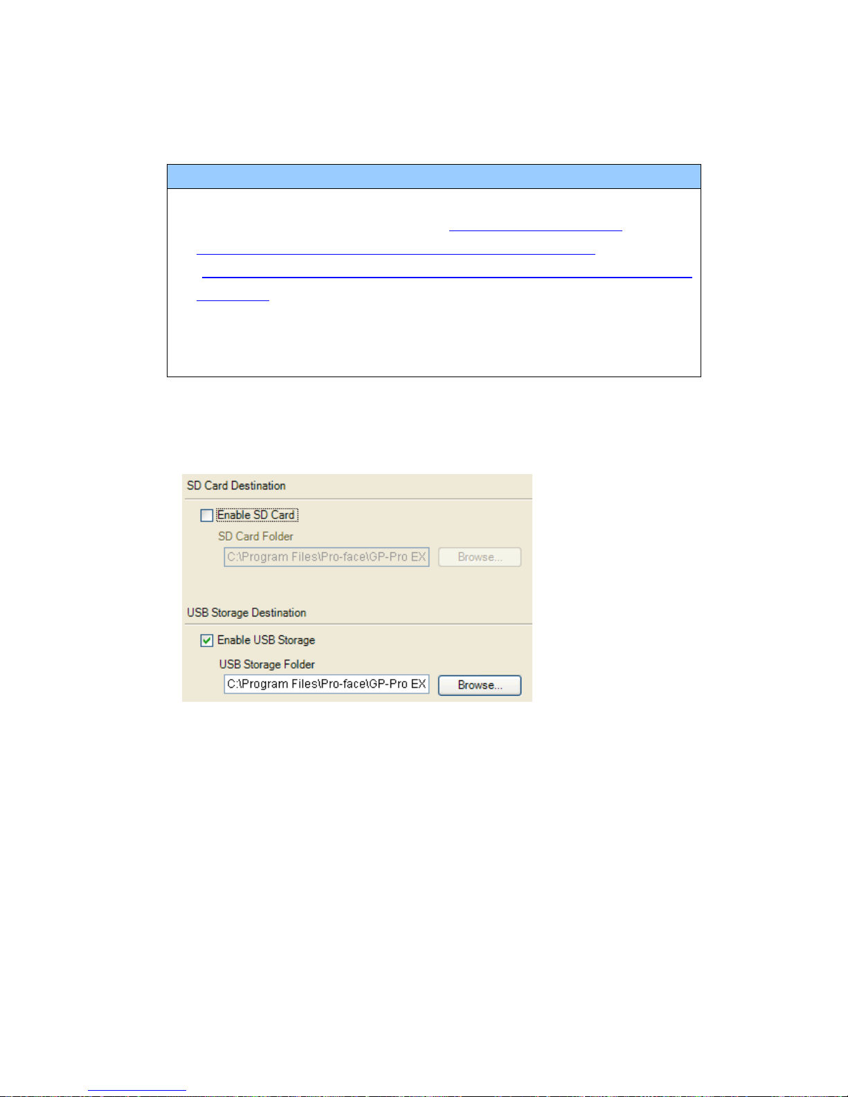
2. Check and change the destination folder setting following the steps below.
i. Click [Project]->[Information]->[Destination Folder].
ii. The current setting is displayed.
iii. After changing it, click [OK] to confirm the setting.
iv. Click [Project]->[Save] to save changes.
59/59
 Loading...