

Page 1

GP-4201TM/4301TM/4000M
Hardware Manual
Page 2

GM4000 Series Hardware Manual
2
The information provided in this documentation contains general descriptions and/or
technical characteristics of the performance of the products contained herein. This
documentation is not intended as a substitute for and is not to be used for
determining suitability or reliability of these products for specific user applications. It
is the duty of any such user or integrator to perform the appropriate and complete
risk analysis, evaluation and testing of the products with respect to the relevant
specific application or use thereof. Neither Pro-face nor any of its affiliates or
subsidiaries shall be responsible or liable for misuse of the information contained
herein. If you have any suggestions for improvements or amendments or have found
errors in this publication, please notify us.
No part of this document may be reproduced in any form or by any means, electronic
or mechanical, including photocopying, without express written permission of Proface.
All pertinent state, regional, and local safety regulations must be observed when
installing and using this product. For reasons of safety and to help ensure
compliance with documented system data, only the manufacturer should perform
repairs to components.
When devices are used for applications with technical safety requirements, the
relevant instructions must be followed.
Failure to use Pro-face software or approved software with our hardware products
may result in injury, harm, or improper operating results.
Failure to observe this information can result in injury or equipment damage.
Copyright © 2014.11 Digital Electronics Corporation. All Rights Reserved.
Page 3

3
Table of Contents
Table of Contents
Safety Information . . . . . . . . . . . . . . . . . . . . . . . . . . . . . . . . . . 5
About the Book. . . . . . . . . . . . . . . . . . . . . . . . . . . . . . . . . . . . . 7
Chapter 1 General Overview . . . . . . . . . . . . . . . . . . . . . . . . . . . . . . . . . . . 9
Package Contents . . . . . . . . . . . . . . . . . . . . . . . . . . . . . . . . . . . . . . . . . . . . . . 10
Parts Identification and Functions . . . . . . . . . . . . . . . . . . . . . . . . . . . . . . . . . . 13
Certifications and Standards . . . . . . . . . . . . . . . . . . . . . . . . . . . . . . . . . . . . . . 16
Chapter 2 Device Connectivity . . . . . . . . . . . . . . . . . . . . . . . . . . . . . . . . . 19
System Design. . . . . . . . . . . . . . . . . . . . . . . . . . . . . . . . . . . . . . . . . . . . . . . . . 20
Accessories . . . . . . . . . . . . . . . . . . . . . . . . . . . . . . . . . . . . . . . . . . . . . . . . . . . 24
Chapter 3 Specifications . . . . . . . . . . . . . . . . . . . . . . . . . . . . . . . . . . . . . . 27
3.1 General Specifications . . . . . . . . . . . . . . . . . . . . . . . . . . . . . . . . . . . . . . . . . . 28
General Specification. . . . . . . . . . . . . . . . . . . . . . . . . . . . . . . . . . . . . . . . . . . . 28
3.2 Functional Specifications . . . . . . . . . . . . . . . . . . . . . . . . . . . . . . . . . . . . . . . . 30
Display . . . . . . . . . . . . . . . . . . . . . . . . . . . . . . . . . . . . . . . . . . . . . . . . . . . . . . . 31
Memory, Clock, and Touch Panel . . . . . . . . . . . . . . . . . . . . . . . . . . . . . . . . . . 32
3.3 Interface Specifications . . . . . . . . . . . . . . . . . . . . . . . . . . . . . . . . . . . . . . . . . . 33
Interface Specifications . . . . . . . . . . . . . . . . . . . . . . . . . . . . . . . . . . . . . . . . . . 34
Specifications of Serial Interface COM1 . . . . . . . . . . . . . . . . . . . . . . . . . . . . . 35
3.4 Dimensions . . . . . . . . . . . . . . . . . . . . . . . . . . . . . . . . . . . . . . . . . . . . . . . . . . . 37
Display Module GP-4201TM . . . . . . . . . . . . . . . . . . . . . . . . . . . . . . . . . . . . . . 37
Display Module GP-4301TM . . . . . . . . . . . . . . . . . . . . . . . . . . . . . . . . . . . . . . 38
Rear Module (for all GP units) . . . . . . . . . . . . . . . . . . . . . . . . . . . . . . . . . . . . . 39
Display and Rear Modules GP-4201TM . . . . . . . . . . . . . . . . . . . . . . . . . . . . . 40
Display and Rear Modules GP-4301TM . . . . . . . . . . . . . . . . . . . . . . . . . . . . . 41
Cable Attached Dimensions . . . . . . . . . . . . . . . . . . . . . . . . . . . . . . . . . . . . . . 42
Separation Cable Attached Dimension . . . . . . . . . . . . . . . . . . . . . . . . . . . . . . 43
DIN Rail Attached Demention . . . . . . . . . . . . . . . . . . . . . . . . . . . . . . . . . . . . . 43
Chapter 4 Installation and Wiring. . . . . . . . . . . . . . . . . . . . . . . . . . . . . . . 45
4.1 Installation . . . . . . . . . . . . . . . . . . . . . . . . . . . . . . . . . . . . . . . . . . . . . . . . . . . . 46
Panel Cut-out Dimensions and Installation . . . . . . . . . . . . . . . . . . . . . . . . . . . 47
Installation Procedures . . . . . . . . . . . . . . . . . . . . . . . . . . . . . . . . . . . . . . . . . . 51
4.2 Wiring Principles . . . . . . . . . . . . . . . . . . . . . . . . . . . . . . . . . . . . . . . . . . . . . . . 57
Connecting the Power Cord. . . . . . . . . . . . . . . . . . . . . . . . . . . . . . . . . . . . . . . 58
Connecting the Power Supply . . . . . . . . . . . . . . . . . . . . . . . . . . . . . . . . . . . . . 60
Grounding . . . . . . . . . . . . . . . . . . . . . . . . . . . . . . . . . . . . . . . . . . . . . . . . . . . . 62
4.3 USB Interface . . . . . . . . . . . . . . . . . . . . . . . . . . . . . . . . . . . . . . . . . . . . . . . . . 64
Important Considerations When Using the USB interface. . . . . . . . . . . . . . . . 65
USB Data Transfer Cable (ZC9USCBMB1) - USB Driver Installation . . . . . . . 66
USB (Type A) interface . . . . . . . . . . . . . . . . . . . . . . . . . . . . . . . . . . . . . . . . . . 67
USB (mini-B) interface. . . . . . . . . . . . . . . . . . . . . . . . . . . . . . . . . . . . . . . . . . . 70
Chapter 5 Maintenance . . . . . . . . . . . . . . . . . . . . . . . . . . . . . . . . . . . . . . . 73
Regular Cleaning . . . . . . . . . . . . . . . . . . . . . . . . . . . . . . . . . . . . . . . . . . . . . . . 74
Page 4

GP-4201TM/4301TM/4000M Hardware Manual
4
Periodic Check Points . . . . . . . . . . . . . . . . . . . . . . . . . . . . . . . . . . . . . . . . . . . 74
After-sales service . . . . . . . . . . . . . . . . . . . . . . . . . . . . . . . . . . . . . . . . . . . . . . 74
Page 5
5
§
Safety Information
Safety Information
Important Information
NOTICE
Read these instructions carefully, and look at the equipment to become familiar with
the device before trying to install, operate, or maintain it. The following special
messages may appear throughout this documentation or on the equipment to warn
of potential hazards or to call attention to information that clarifies or simplifies a
procedure.
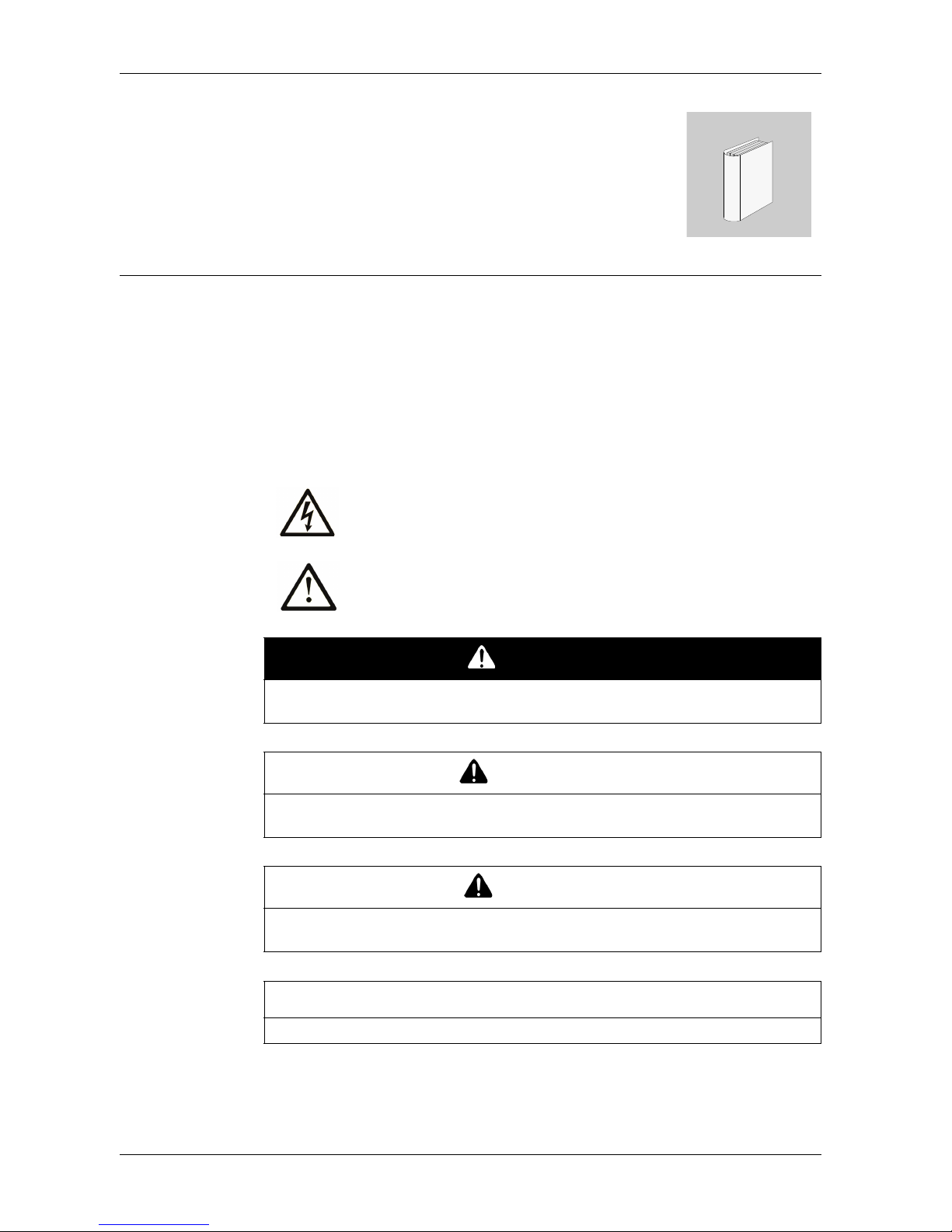
The addition of this symbol to a Danger or Warning safety label
indicates that an electrical hazard exists which will result in personal
injury if the instructions are not followed.
This is the safety alert symbol. It is used to alert you to potential
personal injury hazards. Obey all safety messages that follow this
symbol to avoid possible injury or death.
DANGER
DANGER indicates a hazardous situation which, if not avoided, will result in death
or serious injury.
WARNING
WARNING indicates a hazardous situation which, if not avoided, could result in
death or serious injury.
CAUTION
CAUTION indicates a hazardous situation which, if not avoided, could result in
minor or moderate injury.
NOTICE
NOTICE is used address practices not related to physical injury.
Page 6

GP-4201TM/4301TM/4000M Hardware Manual
6
PLEASE NOTE
Electrical equipment should be installed, operated, serviced, and maintained only by
qualified personnel. No responsibility is assumed by Pro-face for any consequences
arising out of the use of this material.
A qualified person is one who has skills and knowledge related to the construction
and operation of electrical equipment and the installation, and has received safety
training to recognize and avoid the hazards involved.
Page 7
7
About the Book
About the Book
At a Glance
Thank you for purchasing Pro-face's GP-4201TM/4301TM/4000M (Hereafter
referred to as the "GP unit").
Document Scope
This manual describes how to use the GP unit.
Validity Note
This documentation is valid for the GP unit when used with GP-Pro EX version 4.02
or later.
The technical characteristics of the device(s) described in this manual appear
online. To access this information online, please go to our site
http://www.pro-face.com/.
The characteristics presented in this manual should be constantly improved for
clarity and accuracy. In the event that you see a difference between the manual in
your PC and online information, use the online information as your reference.
Product Related Information
Related Documents
You can download these technical publications and other technical information from
our website at http://www.pro-face.com/trans/en/manual/1001.html.
WARNING
UNINTENDED EQUIPMENT OPERATION
The application of this product requires expertise in the design and programming
of control systems. Only persons with such expertise should be allowed to
program, install, alter, and apply this product.
Follow all local and national safety codes and standards.
Failure to follow these instructions can result in death, serious injury, or
equipment damage.
Title of Documentation
GP-Pro EX Reference Manual
GP-Pro EX Device/PLC Connection Manual
GP-Pro EX Maintenance/Troubleshooting
Page 8
GP-4201TM/4301TM/4000M Hardware Manual
8
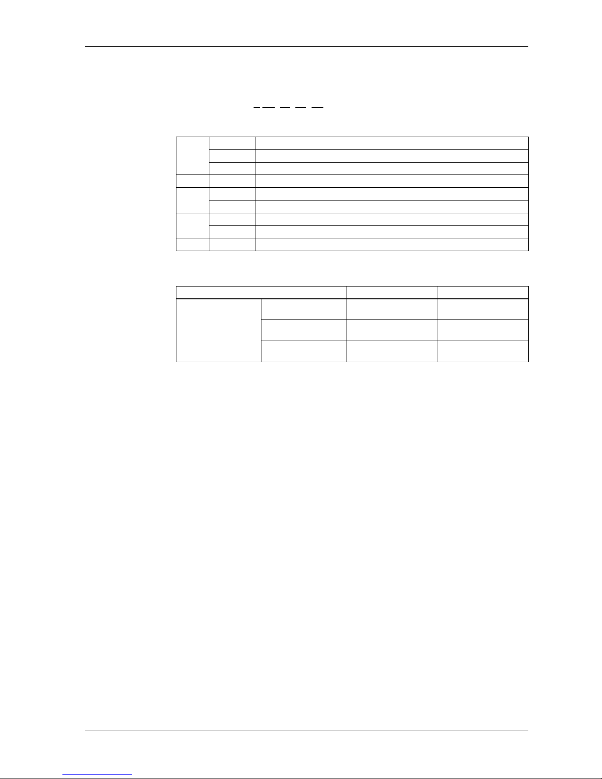
Model Name Indication
Model name
PFXGM4
* ** T A
D
GP-4201TM/4301TM/4000M Model Names
Global Code
A global code is assigned to every Pro-face product as a universal model number.
For more information on product models and their matching global codes, please
refer to the following URL.
http://www.pro-face.com/trans/en/manual/1003.html
A
B
C
E
D
A
2 GP-4200 series (3.5-inch): QVGA (320 x 240 dots)
3 GP-4300 series (5.7-inch): QVGA (320 x 240 dots)
B No display (Rear Module)
B 01 RS-232C/RS-422/RS-485
C
T TFT color LCD
- No display (Rear Module)
D
A Analog Touch Panel
- No display (Rear Module)
E D DC type power supply is used.
Series Names Models
GP4000 Series
GP-4200 Series
GP-4201TM
(Modular Type)
PFXGM4201TAD
GP-4300 Series
GP-4301TM
(Modular Type)
PFXGM4301TAD
GP-Rear Module
GP-4000M
(Rear Modular Type)
PFXGM4B01D
Page 9
9
General Overview
1
EIO0000000614 07/2010
General Overview
Overview
This chapter describes the GP unit's General Overview.
What's in this Chapter?
This chapter contains the following topics:
Topic Page
Package Contents 10
Parts Identification and Functions 13
Certifications and Standards 16
Page 10
GP-4201TM/4301TM/4000M Hardware Manual
10
Package Contents
Package Contents
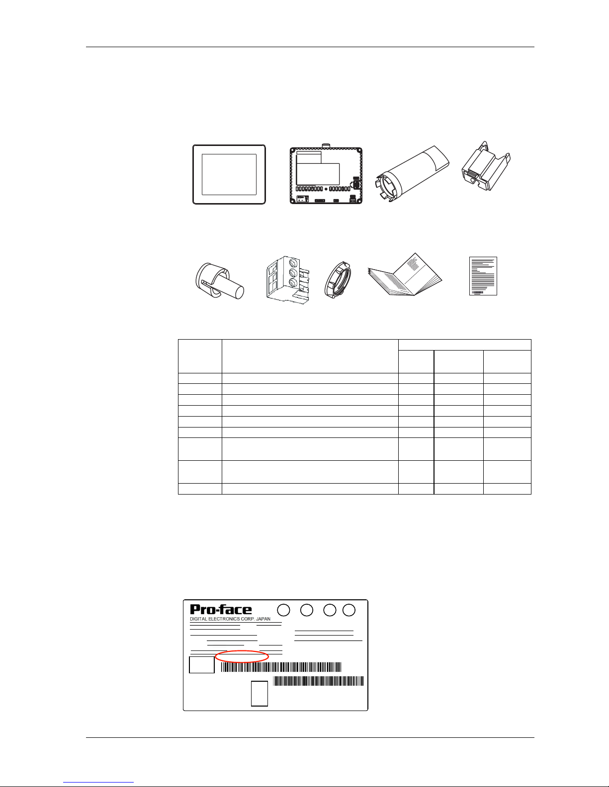
Verify all items listed here are present in your package:
*1. Display Module and Rear Module
Product Label Sticker
You can identify the product version (PV), revision level (RL) and software version
(SV) from the product label on the panel.
The following diagram is a representation of a typical label:
When PV is 03 or later and SV is 3.0 or later, GP can also be used as a rear module.
Legend Description
Package Type
GP *1
Display
Module
Rear
Module
1 Display Module Yes Yes No
2 Rear Module Yes No Yes
3 Socket Wrench Yes No No
4 USB Clamp Type A (1Port) Yes No Yes
5 Anti-rotation Tee Yes Yes No
6 DC Power Supply Connector Yes No Yes
7
Display Installation Nut
(Attached to the Display Module)
Yes Yes No
8
GP-4201TM/4301TM/4000M
Installation Guide
Yes Yes Yes
9 Warning/Caution Information Yes Yes Yes
21
3
65
4
7 89
395/69
Page 11
General Overview
11
Critical systems, Detected Alarms and Handling Requirements
Critical detected alarm indicators and system functions require independent and
redundant protection hardware and/or mechanical interlocks.
If the unit for any reason becomes inoperative (for example, an inoperative
backlight) it may be difficult or impossible to identify a function. Functions that may
present a hazard if not immediately executed, such as emergency stop, must be
provided independently of the unit. The design of the control system must take into
account an inoperative unit (backlight) and that the operator is unable to control the
machine or respond to detected errors using the unit.
When the power is cycled, wait at least 10 seconds before restoring the power to the
GP Unit. Switching the power OFF and ON quickly can damage the unit.
WARNING
LOSS OF CONTROL
Consider the potential failure modes of control paths in the machine control
system design, such as:
The possibility of backlight failure,
Unanticipated link transmission delays or failures,
The operator being unable to control the machine,
The operator making errors in the control of the machine.
Provide a means to achieve a safe state during and after a path failure for critical
control functions such as emergency stop and overtravel stop.
Provide separate or redundant control paths for critical control functions.
Test individually and thorougly each implementation of the GP unit for correct
operation before service.
Failure to follow these instructions can result in death, serious injury, or
equipment damage.
WARNING
UNINTENDED EQUIPMENT OPERATION
Do not use the unit as the only means of control for critical system functions
such as motor start/stop or power control.
Do not use the unit as the only notification device for critical alarms, such as
device overheating or overcurrent.
Failure to follow these instructions can result in death, serious injury, or
equipment damage.
Page 12
GP-4201TM/4301TM/4000M Hardware Manual
12
Handling the LCD Panel
The following characteristics are specific to the LCD unit and are considered normal
behavior:
LCD screen may show unevenness in the brightness of certain images or may
appear different when seen from outside the specified viewing angle. Extended
shadows, or cross-talk, may also appear on the sides of screen images.
LCD screen pixels may contain black and white colored spots and color display
may seem to have changed over time.
When the same image is displayed on the screen for a long period, an after-
image may appear when the image is changed.
NOTE: Do not display the same image for a long time, change the screen image
periodically.
Using Touch Panel Correctly
Use only one finger to select an object on the touch panel.
If the touch panel receives pressure at two or more points at the same time, an
unintended object could be selected.
CAUTION
SERIOUS EYE AND SKIN INJURY
The liquid present in the LCD panel contains an irritant:
Avoid direct skin contact with the liquid.
Wear gloves when you handle a broken or leaking unit.
Do not use sharp objects or tools in the vicinity of the LCD touch panel.
Handle the LCD panel carefully to prevent puncture, bursting, or cracking of the
panel material.
If the panel is damaged and any liquid comes in contact with your skin, immediately
rinse the area with running water for at least 15 min.
If the liquid gets in your eyes, immediately rinse your eyes with running water for
at least 15 minutes and consult a doctor.
Failure to follow these instructions can result in injury or equipment damage.
WARNING
UNINTENDED EQUIPMENT OPERATION
Operate the GP unit touch panel with only one finger.
Do not activate two or more points of the touch panel simultaneously.
Failure to follow these instructions can result in death, serious injury, or
equipment damage.
Page 13
General Overview
13
Parts Identification and Functions
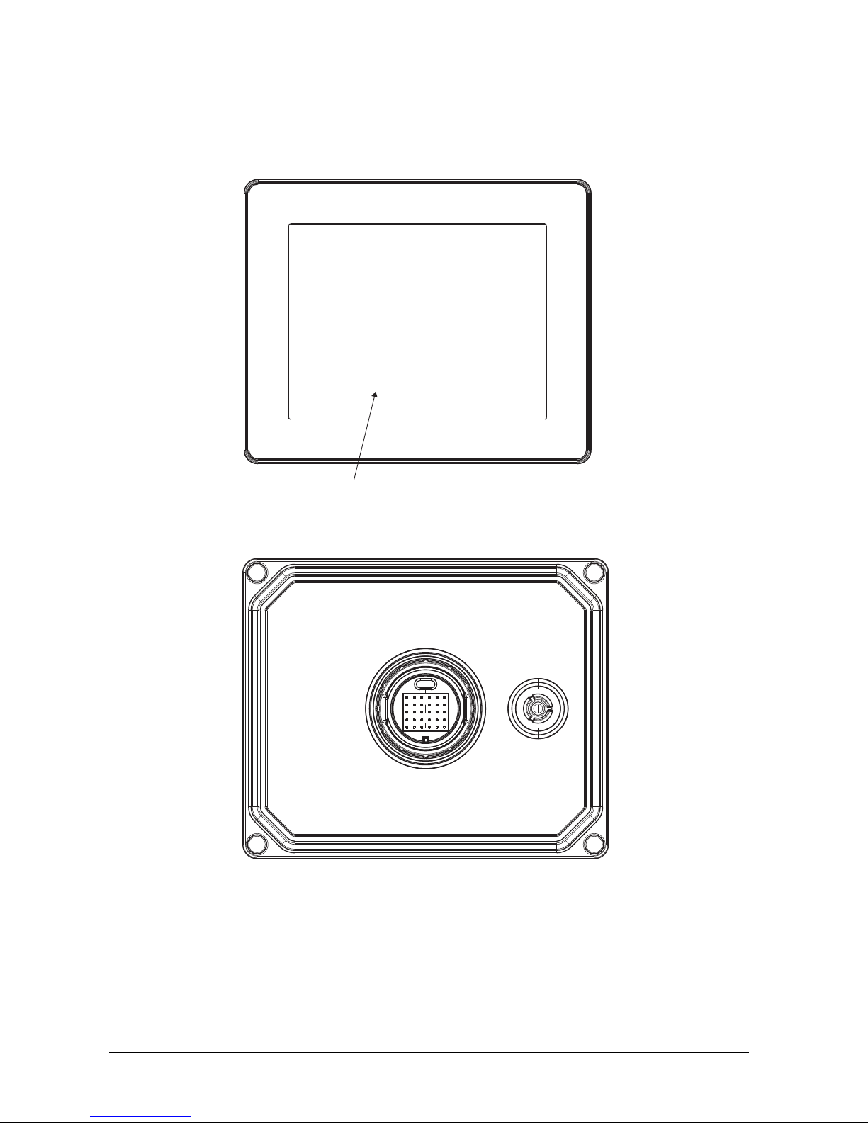
Display Module
Front:
A Display: displays user created screens and remote equipment variables.
B Touch panel: performs screen change operations and sends data to the host (PLC).
Rear:
A, B
Page 14
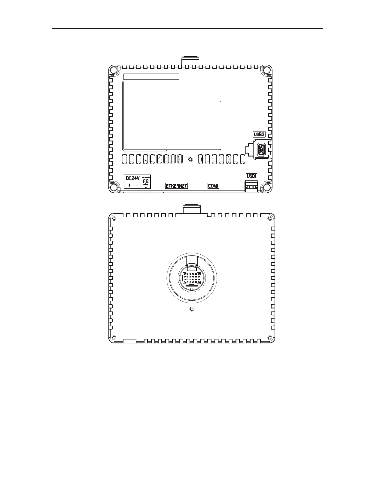
GP-4201TM/4301TM/4000M Hardware Manual
14
Rear Module
Front:
Rear:
Page 15
General Overview
15
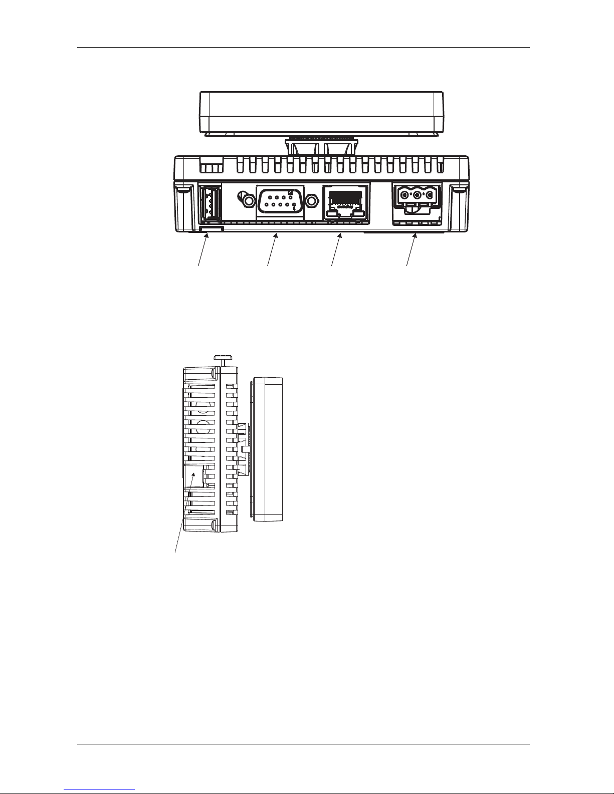
Connectors:
Bottom:
C USB (Type A) interface connector: connects the memory stick to the unit.
D Serial I/F (host I/F): connects a RS232C/RS422/RS485 cable (from the host/PLC) to the
GP unit. D-Sub 9-pin plug type connector.
E Ethernet Interface (LAN): connects an Ethernet cable (from the host/PLC) to the unit.
F DC Power Supply Connector: connects the power input and ground wires to the unit.
Side:
G USB (mini-B) interface connector: connects the data transfer PC cable to the unit.
C D
E
F
G
Page 16

GP-4201TM/4301TM/4000M Hardware Manual
16
Certifications and Standards
Introduction
Pro-face submitted this product for independent testing and qualification by thirdparty listing agencies. These agencies have certified this product as meeting the
following standards.
For information on Standards and Regulations, such as certified models and
certificates, see the following.
http://www.pro-face.com/trans/en/manual/1002.html
Agency Certifications for GP Unit
GP unit is certified by the Underwriters Laboratory according to:
UL 508 and CSA C22.2 n142 for Industrial Control Equipment
ANSI/ISA 12.12.01 and CSA C22.2 n213 for Electrical Equipment for Use in Class
I, Division 2 Groups A, B, C and D Hazardous (classified) Locations
NOTE:
For use in Pollution Degree 2 environments.
For use on a flat surface of Type 4X Enclosure.
Hazardous Substances
GP unit is designed for compliance with:
WEEE, Directive 2012/19/EU
RoHS, Directive 2011/65/EU and 2015/863/EU
RoHS China, Standard (GB/T 26572)
Page 17
General Overview
17
UL Conditions of Acceptability and Handling Cautions for GP Unit
The GP unit is suitable for use in hazardous locations in accordance with Class I,
Division 2 Groups A, B, C and D standards. All relevant local, state, and regional
codes must be followed.
WARNING
RISK OF EXPLOSION IN HAZARDOUS LOCATIONS
Verify that the power, input and output (I/O) wiring are in accordance with Class
I, Division 2 wiring methods.
Substitution of any components may impair suitability for Class I, Division 2.
Do not disconnect equipment unless power has been switched off or the area
is known to be Non-Hazardous.
Securely lock externally connected units and each interface before turning on
the power supply.
Do not disconnect while circuit is live unless area is known to be Non-
Hazardous.
USB mini-B connector is for temporary connection only. Do not use, connect, or
disconnect unless area is known to be non-hazardous.Connection or
disconnection in an explosive atmosphere could result in an explosion.
Potential electrostatic charging hazard: wipe the front panel of the terminal with
a damp cloth before turning ON.
Do not substitute a rear module labeled GP-4201TM/4301TM by a rear module
labeled PFXGM4B01D when installed in Hazardous Locations.
Failure to follow these instructions can result in death, serious injury, or
equipment damage.
Page 18
GP-4201TM/4301TM/4000M Hardware Manual
18
CE Markings
This product conforms to the necessary requirements of the following Directives for
applying the CE label:
Directive 2014/35/EU (Low Voltage)
Directive 2014/30/EU (EMC)
This conformity is based on compliance with EN 61131-2.
KC Markings
GGGG㇠㟝㣄㙼⇨ⱬ
ὤG㦹Gⷸ
㇠GG㟝GG㣄GG㙼GG⇨GGⱬ
GhἽGὤὤ
O㛹ⱨ㟝Gⵝ㋕䋩㐔ὤ㣄㣠P
㢨Gὤὤ⏈G㛹ⱨ㟝OhἽPG㤸㣄䑀㤵䚝ὤὤ⦐㉐G䑄⬘㣄G❄⏈G㇠㟝㣄
⏈G㢨G㥄㡸G㨰㢌䚌㐐ὤGⵈ⢰⮤SGᴴ㥉㞬㢌G㫴㜡㜄㉐G㇠㟝䚌⏈Gᶷ㡸
⯝㤵㡰⦐G䚝⏼␘U
Page 19
19
Device Connectivity
2
EIO0000000614 07/2010
Device Connectivity
Introduction
This chapter presents the equipment connectable to GP unit.
What's in this Chapter?
This chapter contains the following topics:
Topic Page
System Design 20
Accessories 24
Page 20
GP-4201TM/4301TM/4000M Hardware Manual
20
System Design
Introduction
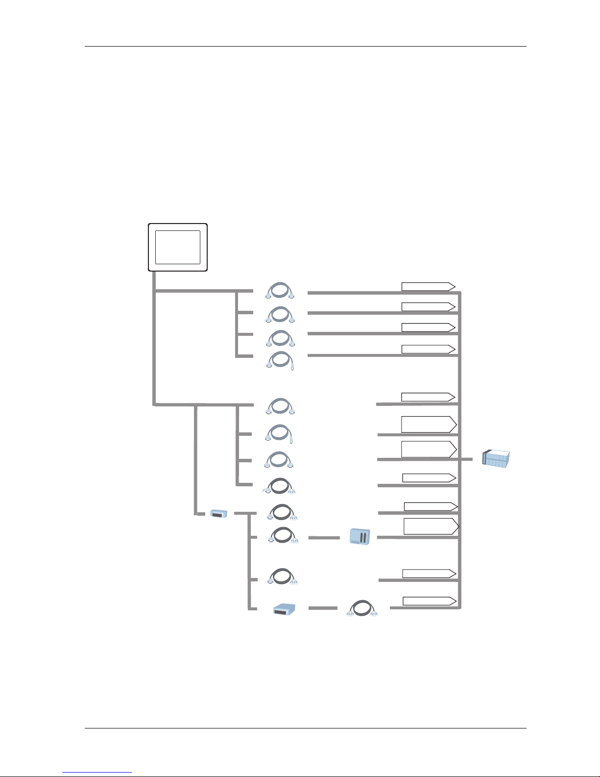
The following diagrams represent equipment that can be connected to the unit.
RUN Mode Peripherals - Serial Communication
NOTE:
For instructions on how to connect to other devices, always refer to the “GP-Pro EX
Device/PLC Connection Manual”.
RS-232C Cable
CA3-CBL232/5M-01
GP unit
Mitsubishi PLC Q-Series Link Cable
CA3-CBLLNKMQ-01
Omron PLC SYSMAC Link Cable
CA3-CBLSYS-01
Mitsubishi PLC Q-Series Connection Cable
CA3-CBLQ-01
Mitsubishi PLC
A-Series Connection Cable
CA3-CBLA-01
Mitsubishi PLC
FX-Series Connection Cable
CA3-CBLFX/1M-01
CA3-CBLFX/5M-01
Host Controller
PLC etc.
MPI Cable
ST03-A2B-MPI21-PFE
RS-232C Port
RS-232C Port
RS-232C Port
RS-232C Port
RS-485 Port
Programming
Console Port
Programming
Console Port
Serial Interface (COM1)
(RS-232C mode)
Serial Interface(COM1)
(RS-422 mode)
RS-422 Cable
CA3-CBL422/5M-01
RS-422 Cable
(Prepared by user)
RS-422 Cable
CA3-CBL422-01
Terminal Block
Conversion Adapter
CA3-ADPTRM-01
Mitsubishi PLC A, QnA,
FX Series' 2 Port Adapter II
GP070-MD11
2 Port
Adapter Cable
CA3-MDCB11
COM Port
Conversion
Adapter
CA3-ADPCOM-01
RS-422 Port
Programming
Console Port
RS-422 Port
RS-422 Port
Multi-Link Cable
CA3-CBL422-01
RS-422 Port
Page 21
Device Connectivity
21
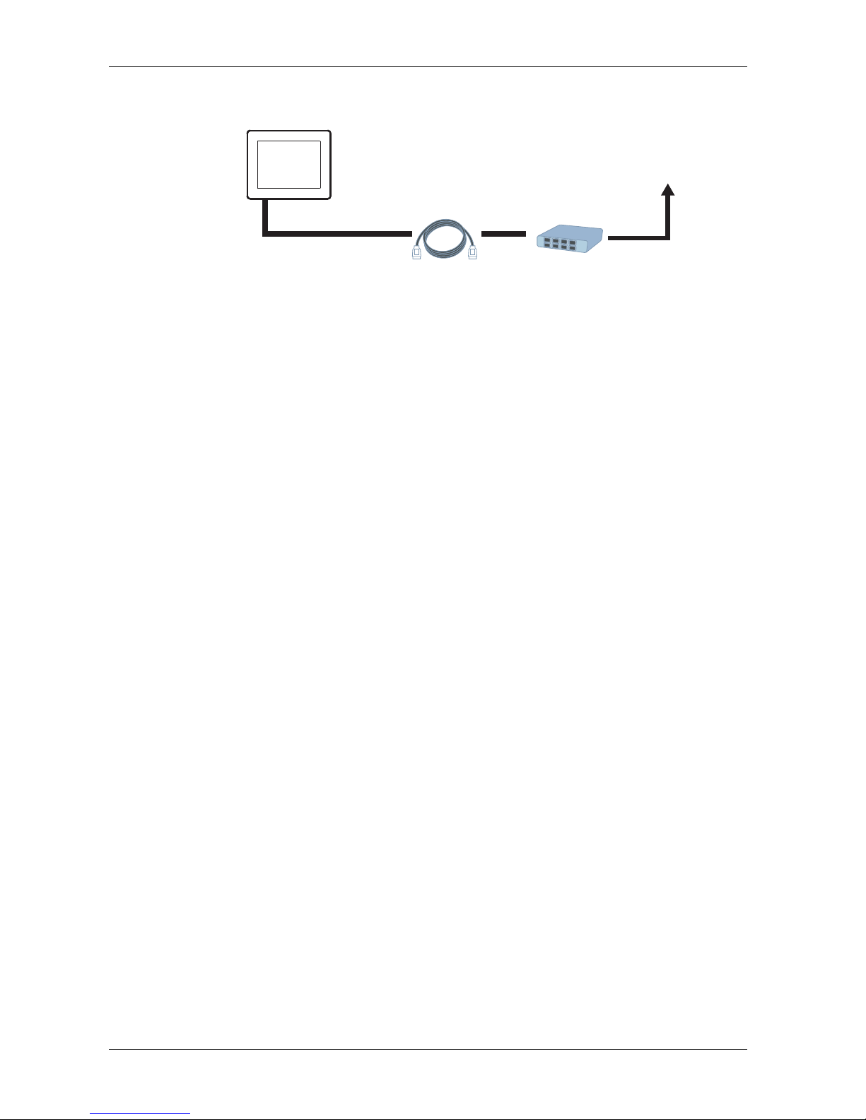
RUN Mode Peripherals - Ethernet Communication
GP unit
Ethernet Interface
(10BASE-T/100BASE-TX)
Twisted Pair Cable
(commercial type)
Hub
(commercial type)
To an Ethernet Network
Page 22
GP-4201TM/4301TM/4000M Hardware Manual
22
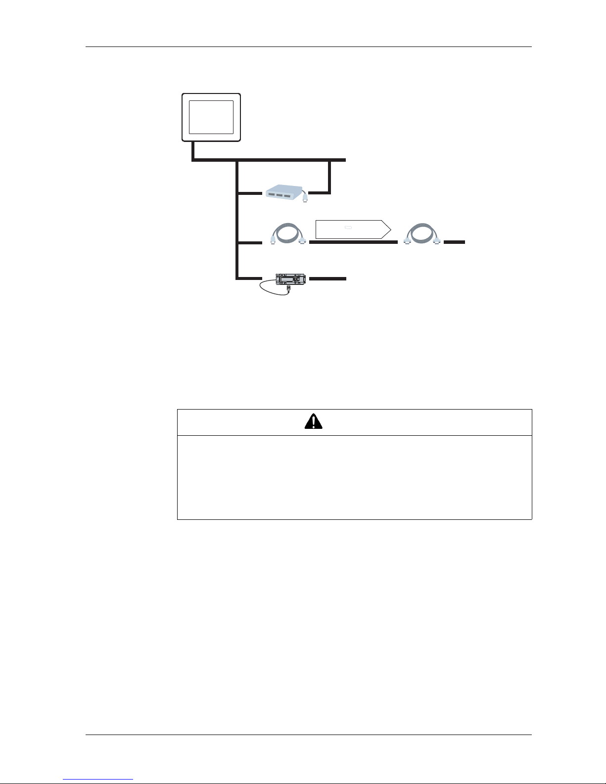
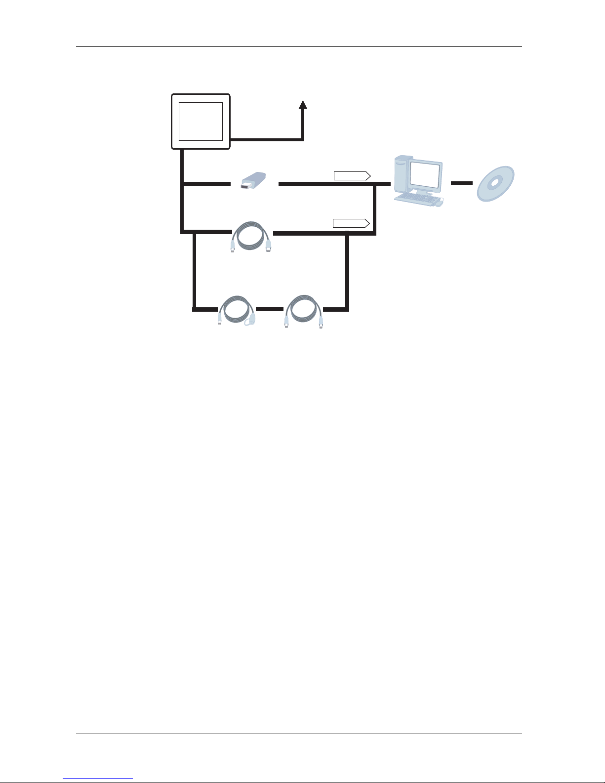
RUN Mode Peripherals - USB Interface
*1 Refer to the System Design (see page 20)
*2 For supported models, refer to Pro-face's support site (http://www.pro-
face.com/trans/en/manual/1001.html).
You can connect to this site by clicking the GP-Pro EX's [Help (H)] menu-
[Connect to Support Site "Otasuke Pro!" (C)] command.
CAUTION
GP UNIT RESET
If connecting a bus-powered bar code reader or EZ Illuminated Switch and so
on to the GP unit, be sure to supply power from an external source (such as a
self-powered hub). If you supply power from the GP unit, the GP unit may reset
itself because the GP unit cannot supply enough power.
Failure to follow these instructions can result in injury or equipment damage.
GP unit
USB (Type A) Interface
(USB1)
USB device*1
USB device (commercial type)*2
USB Hub
(Commercial type)
USB-Serial (RS-232C)
Conversion Cable
CA6-USB232-01
RS-232C Cable
(Prepared by user)
Microcomputer Board, etc...
Communication using
the Screen Creation Software’s
Extended SIO Feature
External Device (RS-422/485)
USB/RS-422/485
Conversion Adapter
PFXZCBCBCVUSR41
Page 23
Device Connectivity
23
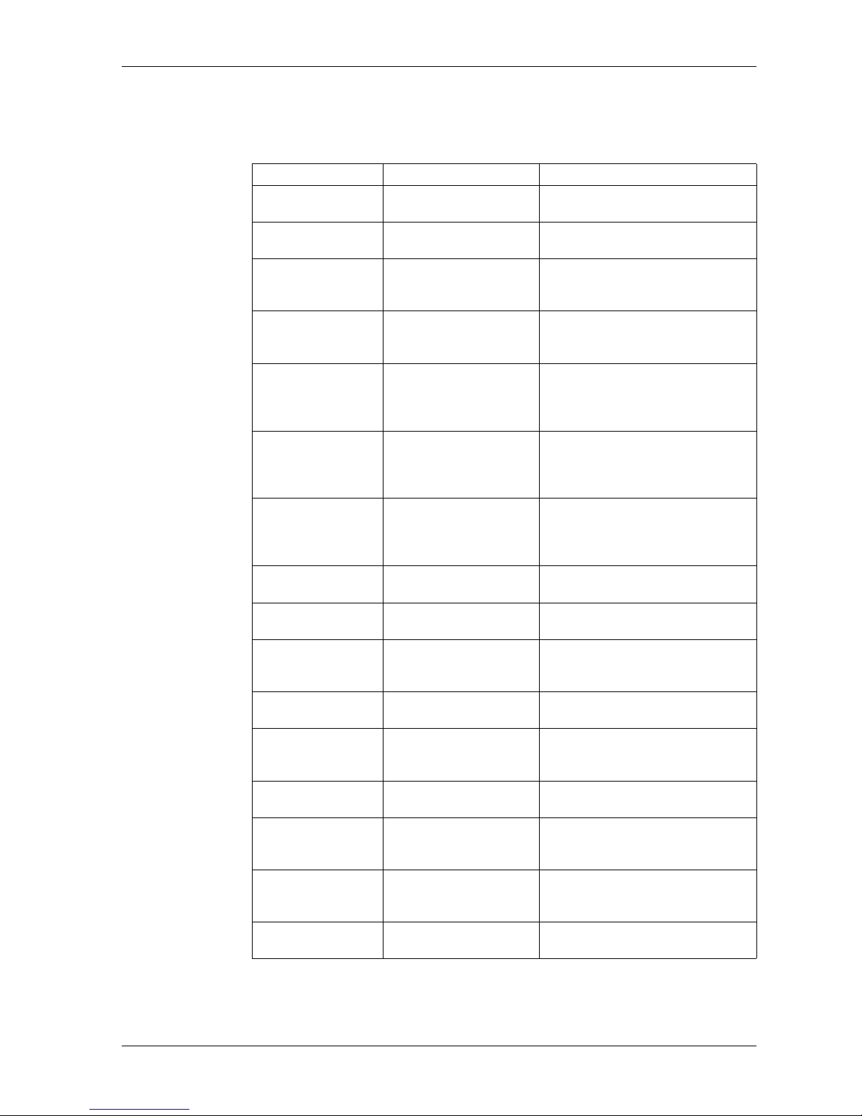
Edit Mode Peripherals
*1 For supported models, refer to Pro-face's support site (http://www.pro-
face.com/trans/en/manual/1001.html).
You can connect to this site by clicking the GP-Pro EX's [Help (H)] menu[Connect to Support Site "Otasuke Pro!" (C)] command.
*2 Certain types and models of PCs cannot be used.
Refer to GP-Pro EX Reference Manual.
GP unit
USB (Type A) Interface
(USB1)
Ethernet Interface
(10BASE-T/100BASE-TX)
To an Ethernet Network
USB (mini B) Interface
(USB2)
USB Memory Strage
*1
(Commercial type)
USB Port
USB Port
USB Data Transfer Cable
(USB A/mini-B)
ZC9USCBMB1 or
Commercial Type
USB Data Transfer Cable
(USB A/mini-B)
ZC9USCBMB1 or
Commercial Type
Personal Computer
(Commercial type)
*2
Screen Editor
Software
GP-Pro EX
USB Panel-mount
Extension Cable
(USB mini-B)
ZC9USEXMB1
Page 24
GP-4201TM/4301TM/4000M Hardware Manual
24
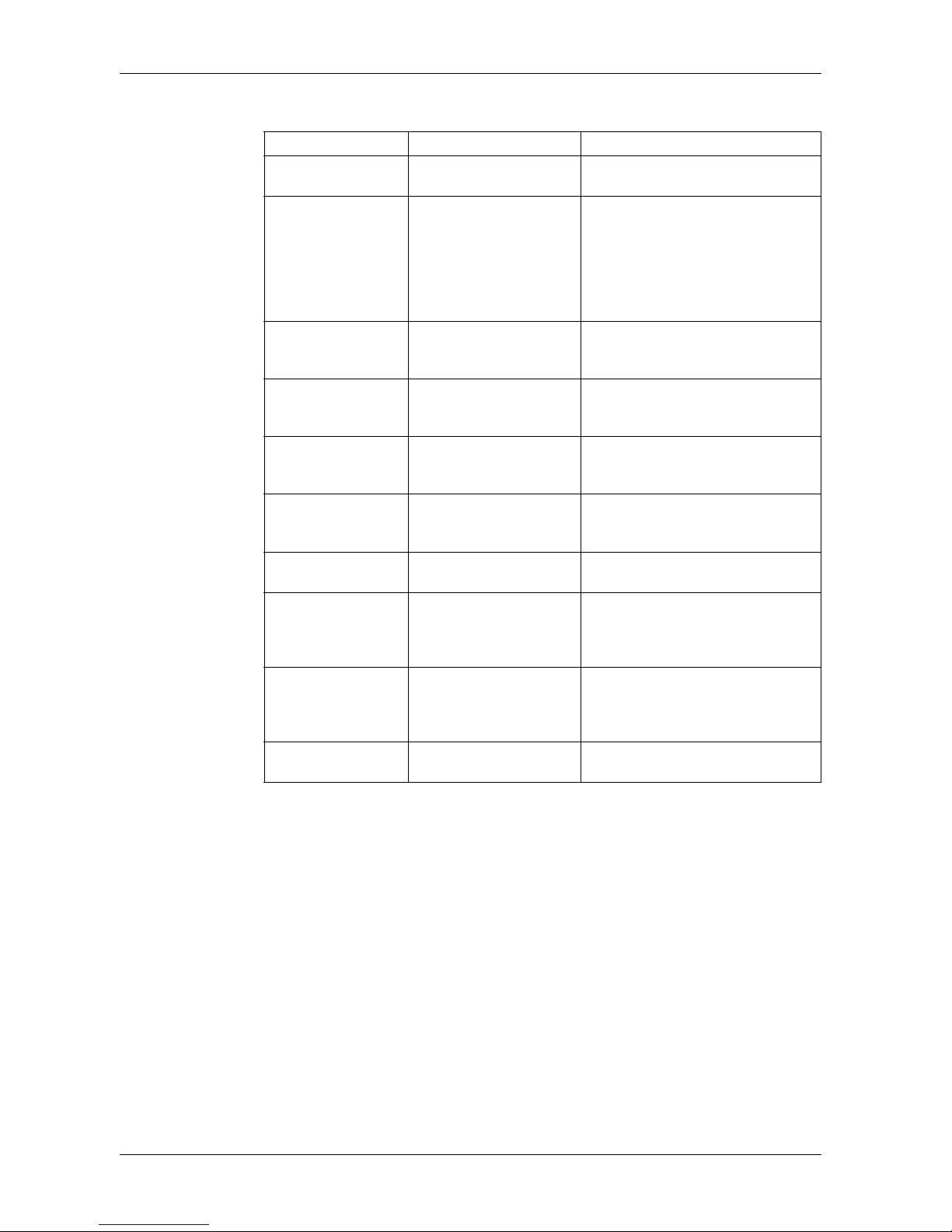
Accessories
Serial Interface Item
Product Name Model No. Description
RS-232C Cable (5m) CA3-CBL232/5M-01 Connects a host controller to the GP
unit. (RS-232C)
RS-422 Cable (5m) CA3-CBL422/5M-01 Connects a host controller to the GP
unit. (RS-422 / Socket Type)
Mitsubishi PLC
Q-Series Link Cable
(5m)
CA3-CBLLNKMQ-01 Connects Mitsubishi PLC Q-Series
(or other host controller) to the GP unit.
(RS-232C)
Omron PLC SYSMAC
Link Cable (5m)
CA3-CBLSYS-01 Connects Omron PLC SYSMAC
Series unit (or other host controller) to
the GP unit. (RS-232C)
Mitsubishi PLC
A-Series Connection
Cable (5m)
CA3-CBLA-01 Connects Mitsubishi PLC A, QnA
Series programming console I/F to GP
unit. (Simultaneous use of
programming console is not possible.)
Mitsubishi PLC
Q-Series Connection
Cable (5m)
CA3-CBLQ-01 Connects Mitsubishi PLC Q-Series
programming console I/F to GP unit.
(Simultaneous use of programming
console is not possible.)
Mitsubishi PLC
FX-Series Connection
Cable
CA3-CBLFX/1M-01 (1m)
CA3-CBLFX/5M-01 (5m)
Connects Mitsubishi PLC FX-Series
programming console I/F and GP unit.
(Simultaneous use of programming
console is not possible.)
RS-422 Cable (5m) CA3-CBL422-01 Connects a host controller to the GP
unit. (RS-422 / Plug Type)
2 Port Adapter Cable
(5m)
CA3-MDCB11 Connects Mitsubishi PLC to the GP
unit using 2 port adapter II (RS-422).
Mitsubishi PLC A,
QnA, FX Series 2 Port
Adapter II
GP070-MD11 Allows simultaneous use of an GP unit
Series unit and a Mitsubishi PLC A,
QnA, FX Series peripheral device.
Terminal Block
Conversion Adapter
CA3-ADPTRM-01 Connects output from a serial interface
with an RS-422 terminal block.
COM Port Conversion
Adapter
CA3-ADPCOM-01 Connects optional RS-422
communication items to GP unit's
COM1 port.
Multi-Link Cable CA3-CBLMLT-01 (5m) Connects a host controller to the GP
for multi-link (n:1) communication.
9-pin-to-25-pin RS232C Conversion
Cable
CA3-CBLCBT232-01
(0.2m)
Connects a standard RS-232C cable
(GP Connector,D-Sub 25-pin) to the
GP.
9-pin-to-25-pin RS422 Conversion Cable
CA3-CBLCBT422-01
(0.2m)
Connects a standard RS-422 cable
(GP Connector,D-Sub 25-pin) to the
GP.
MPI Cable (3.5m) ST03-A2B-MPI21-PFE Connects a host controller to the GP
unit for MPI communication.
Page 25
Device Connectivity
25
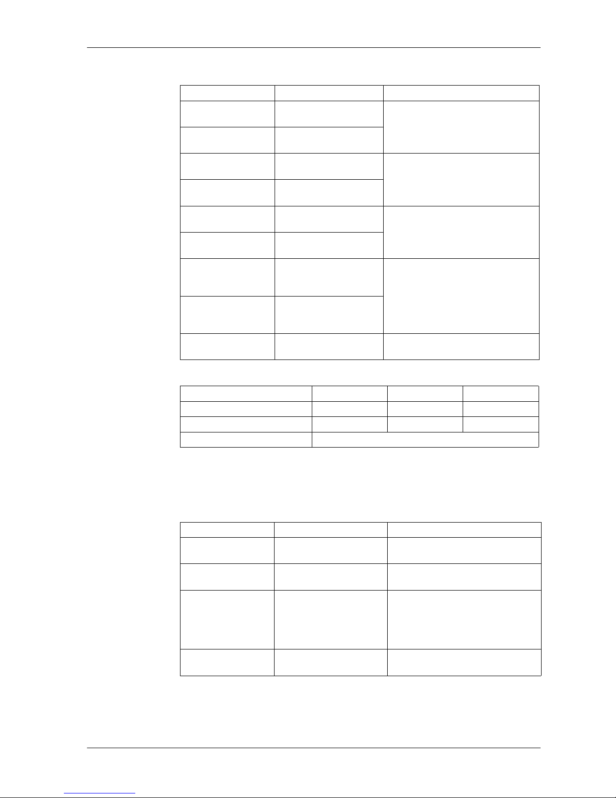
USB Interface Item
*1 Requires an RS-232C cable (prepared by user) for connection. For details
regarding system design, refer to "RUN Mode Peripherals - USB Interface"
(page 22).
Product Name Model No. Description
USB Front Cable (1m) CA5-USBEXT-01 Extension cable attaching USB
interface to front panel.
USB-Serial (RS232C) Conversion
Cable (0.5m)
CA6-USB232-01 Cable for converting a GP unit's USB
interface into a serial interface (RS232C).
Can be used to transfer project data
created with the Screen Editor&Logic
Program Software via a serial
interface.
*1
USB Transfer Cable
(USB Type A/mini-B)
(1.8 m)
ZC9USCBMB1 Cable for transferring screen data from
a PC (USB Type A) to the GP unit
(USB mini-B).
USB Panel-mount
Extension Cable (USB
mini-B) (1 m)
ZC9USEXMB1 Extension cable attaching to the USB
(mini-B) interface on the front side of
the operation panel.
USB/RS-422/485
Conversion Adapter
PFXZCBCBCVUSR41 Adapter for connecting this product
(USB Type A) to an external device
(RS-422/RS-485).
EZ Illuminated Switch PFXZCCEUSG1 A unit of 5 illuminated switches with
multiple color LED easily connected
with GP unit via USB.
EZ Fingerprint
Recognition Unit
PFXZCCEUSS1 Fingerprint recognition unit easily
connected with GP unit via USB.
EZ Tower Light tube
mounting with fixing
plate
PFXZCETWHA1 USB Connection Type Monolithic EZ
Tower Light tube mounting with fixing
plate 3 tiers, ɔ60, lighting and flashing
with a buzzer.
EZ Tower Light with
base mounting
PFXZCETWW1 USB Connection Type Monolithic EZ
Tower with base mounting 3 tiers,
ɔ60, lighting and flashing with a
buzzer.
EZ Numpad PFXZCCEUKB1 Numpad connected to this product via
USB.
Page 26
GP-4201TM/4301TM/4000M Hardware Manual
26
Option Items
*1Available for the product which meets the requirements below.
You can identify the product version (PV), revision level (RL) and software version
(SV) from the Product Label Sticker (page 10).
Maintenance Items
Product Name Model No. Description
3.5 inch Screen
Protection Sheet
CA6-DFS4-01 Disposable, dirt-resistant sheet for the
GP unit's screen.
(5 sheets/set) (Hard type)
5.7 inch Screen
Protection Sheet
PFXZCBDS61
3.5 inch UV Protection
Sheet
PFXZCFUV41 Sheet to protect the display from dirt
and ultraviolet light (1 piece)
5.7 inch UV Protection
Sheet
PFXZCFUV61
3.5 inch display module
PFXXM4200TP Display module for GP4000 Series
5.7 inch display module
PFXXM4300TP
Display module/Rear
module separation cable (3m)
PFXZXMADSM31 Cable with hook to install a rear module
on a DIN rail while connecting the rear
module to a separated display module.
*1
Display module/Rear
module separation cable (5m)
PFXZXMADSM51
Rear module installation adapter
PFXZXMADSA1 DIN rail installation adapter for rear
modules in non-display operation.
Names PV RL SV
GP-4201TM (Modular Type) 03 or later 07 or later 4.0 or later
GP-4301TM (Modular Type) 03 or later 08 or later 4.0 or later
GP-4000M (Rear Modular Type) All revisions
Product Name Model No. Description
Display Installation
Nut
PFXZGMNT1 Nut to install the display module (10
pcs/set)
Socket Wrench PFXZGMSW1 Socket wrench to tighten and loosen
the display installation nut
Accessories Kit PFXZGMAK1 Anti-rotation Tee, USB cable clamp to
prevent disconnection (Type A, MiniB, for 1 port), 2mm-hight spacer to
adjust installation panel thickness
(1pcs/each)
DC Power Supply
Connector
PFXZGMCNDC1 Connector to connect DC power
supply cables (5 pcs/set)
Page 27
27
Specifications
3
EIO0000000614 07/2010
Specifications
Overview
This chapter presents the GP unit specifications.
What's in this Chapter?
This chapter contains the following sections:
Section Topic Page
3.1 General Specifications 28
3.2 Functional Specifications 30
3.3 Interface Specifications 33
3.4 Dimensions 37
Page 28
GP-4201TM/4301TM/4000M Hardware Manual
28
3.1 General Specifications
General Specification
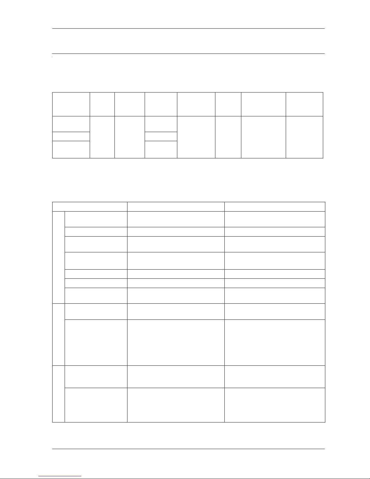
Electrical Specifications
*1 You must use DC input with a Class 2 power supply.
*2 Display Module: 1.6 W or less / Rear Module: 5.2 W or less.
Environmental Specifications
Rated
Input
Voltage
Input
Voltage
Limits
Voltage
Drop
Power
Consumption
In-Rush
Current
Voltage Endurance
Insulation
Resistance
GP-4201TM 24 Vdc*120.4...28.8
Vdc
10 ms or
less
6.8 W or less*230 A or
less
1,000 Vac 20 mA
for 1 min
(between
charging and FG
terminals)
500 Vdc,
10 M or
more
(between
charging and
FG terminals)
GP-4301TM ms or less
GP-4000M ms or less
GP-4201TM GP-4301TM
Physical Environment
Surrounding Air Temperature
0...50 C (32...122 F) 0...50 C (32...122 F)
Storage Temperature -20...60 C (-4...140 F) -20...60 C (-4...140 F)
Surrounding Air and
Strage Humidity
85% RH (Wet bulb temperature: 39 C
(102.2 F) or less - no condensation.)
85% RH (Wet bulb temperature: 39 C
(102.2 F) or less - no condensation.)
Dust
0.1 mg/m
3
(10-7oz/ft3) or le s s
(non-conductive levels)
0.1 mg/m3 (10-7oz/ft3) or l es s
(non-conductive levels)
Pollution Degree
For use in Pollution Degree 2 environment
For use in Pollution Degree 2 environment
Corrosive Gases Free of corrosive gases Free of corrosive gases
Atmospheric Pressure
(Operating Altitude)
800...1,114 hPa (2,000 m (6,561 ft) or
lower)
800...1,114 hPa (2,000 m (6,561 ft) or
lower)
Mechanical Environment
Vibration Resistance EN 61131-2 compliant
5...9 Hz Single amplitude: 3.5 mm (0.14 in)
EN 61131-2 compliant
5...9 Hz Single amplitude: 3.5 mm (0.14 in)
Shock Resistance IEC/EN 61131-2 compliant
147 m/s
2
, X, Y, Z 3directions
IEC/EN 61131-2 compliant
147 m/s2, X, Y, Z 3directions
Electrical Environment
Electrical fast
transient/burst
IEC 61000-4-4
2 kV Power port
1 kV Signal ports
IEC 61000-4-4
2 kV Power port
1 kV Signal ports
Electrostatic Discharge
Immunity
IEC 61000-4-2
6 kV Contact discharge
8 kV Air discharge
IEC 61000-4-2
6 kV Contact discharge
8 kV Air discharge
Page 29
Specifications
29
Structural Specifications
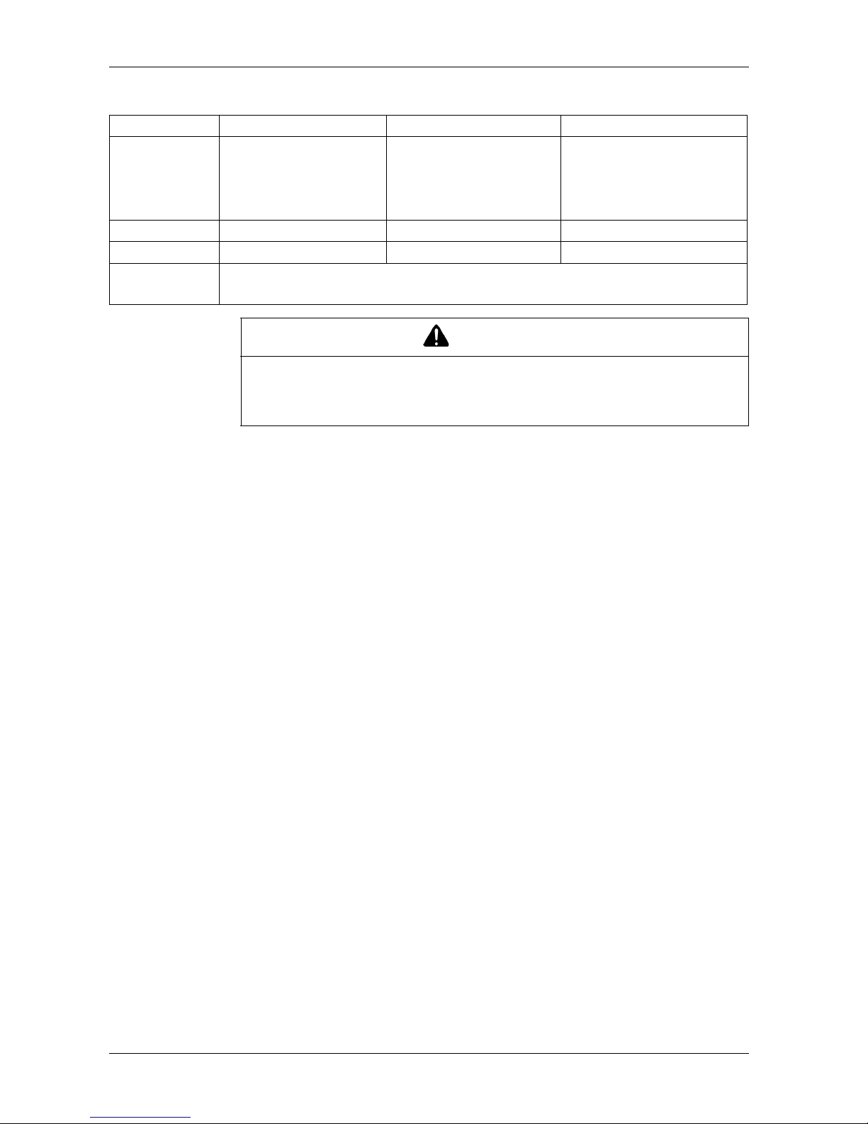
GP-4201TM GP-4301TM GP-4000M
Structure NEMA#250 TYPE 4X
(indoor, installed in an
enclosure)
Front panel: IP 65f
Rear panel: IP 20
NEMA#250 TYPE 4X (indoor,
installed in an enclosure)
Front panel: IP 65f
Rear panel: IP 20
IP 20
Cooling Method Natural air circulation Natural air circulation Natural air circulation
Weight 0.36 kg (0.79 lb.) or less 0.62 kg (1.36 lb) or less 0.21 kg (0.46 lb) or less
Grounding
Functional grounding: Grounding resistance of 100
, 2 mm
2
(AWG 14) orthicker wire, or your
country's applicable standard.
CAUTION
EQUIPMENT DAMAGE
Do not expose the device in direct sunlight.
Failure to follow these instructions can result in injury or equipment damage.
Page 30
GP-4201TM/4301TM/4000M Hardware Manual
30
3.2 Functional Specifications
Overview
This section presents the unities functional specifications of the display, memory
and interfaces.
What's in this Section?
This section contains the following topics:
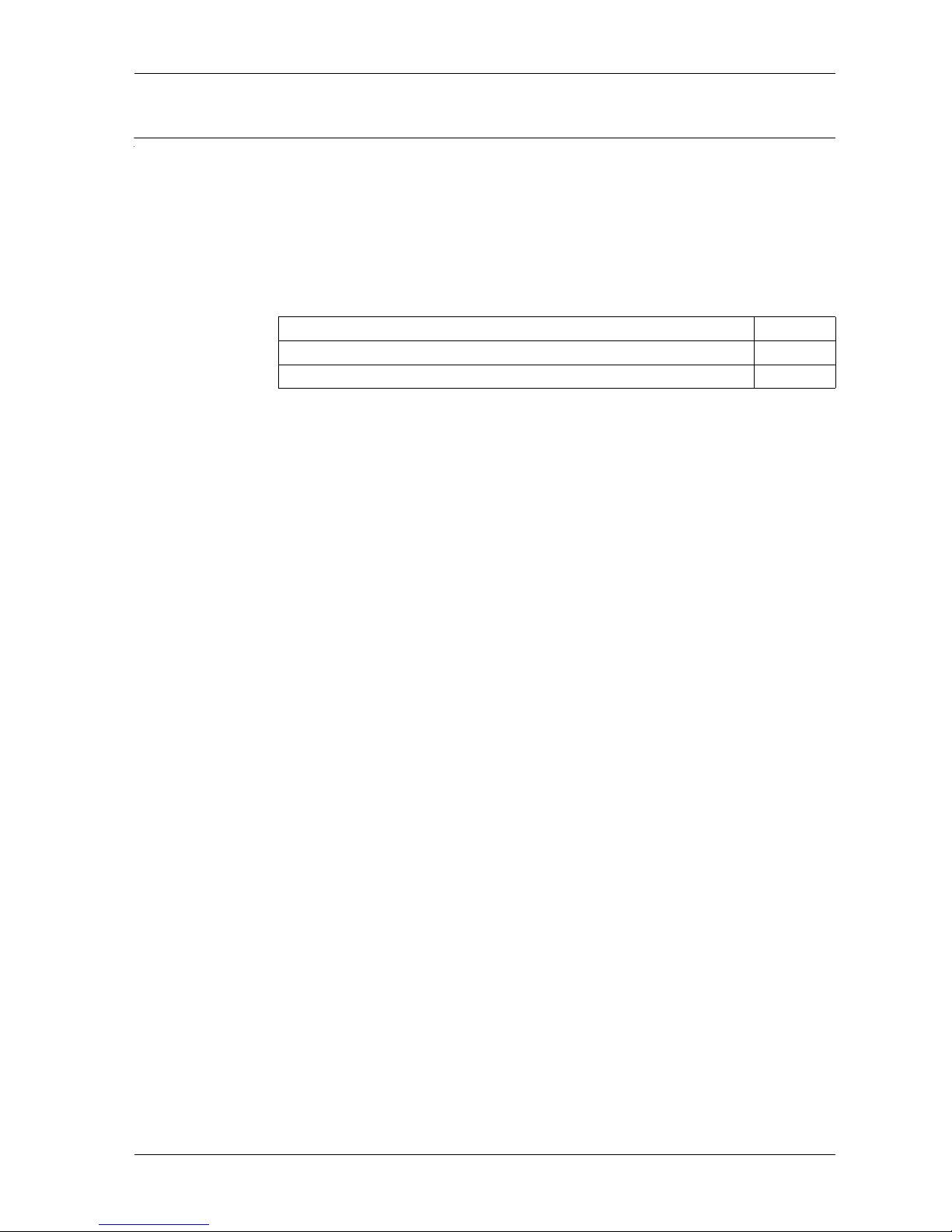
Topic Page
Display 31
Memory, Clock, and Touch Panel 32
Page 31
Specifications
31
Display
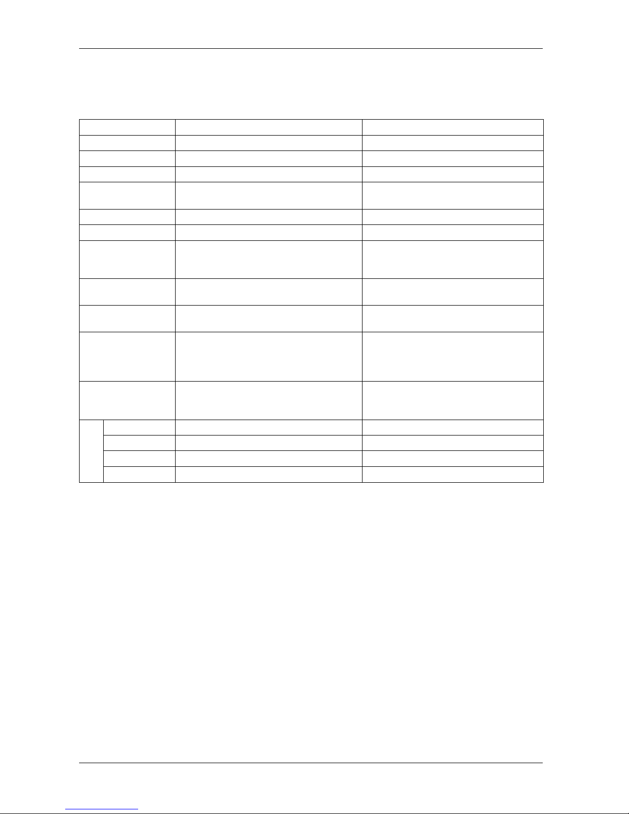
Display Specifications
GP-4201TM GP-4301TM
Display Type TFT Color LCD TFT Color LCD
Display Size 3.5” 5.7”
Resolution 320 x 240 pixels (QVGA) 320 x 240 pixels (QVGA)
Effective Display Area W70.56 x H52.92 mm
(W2.78 x H2.08 in)
W115.2 x H86.4 mm
(W4.53 x H3.40 in)
Display Colors 65,536 colors 65,536 colors
Backlight White LED (User nonreplaceable parts.) White LED (User nonreplaceable parts.)
Backlight Service Life 50,000 hrs. or more (continuous operation at
25 C (77 F) before backlight brightness
decreases to 50%)
50,000 hrs. or more (continuous operation at
25 C (77 F) before backlight brightness
decreases to 50%)
Brightness Control 16 Levels (Adjusted with the touch panel or
the software)
16 Levels (Adjusted with the touch panel or
the software)
Language Fonts
*1
Japanese, ASCII, Chinese (Simplified),
Chinese (Traditional), Korean, Cyrillic, Thai
Japanese, ASCII, Chinese (Simplified),
Chinese (Traditional), Korean, Cyrillic, Thai
Character Sizes Standard font: 8 x 8, 8 x 16, 16 x 16 and 32 x
32 pixel fonts
Stroke font: 6...127 pixel fonts
Image font: 8...72 pixel fonts
Standard font: 8 x 8, 8 x 16, 16 x 16 and 32
x 32 pixel fonts
Stroke font: 6...127 pixel fonts
Image font: 8...72 pixel fonts
Font Sizes Standard font: Width can be expanded up to 8
times. Height can be expanded up to 8 times.
Standard font: Width can be expanded up to
8 times. Height can be expanded up to 8
times.
Text
8 x 8 pixels 40 characters x 30 rows 40 characters x 30 rows
8 x 16 pixels 40 characters x 15 rows 40 character x 15 rows
16 x 16 pixels 20 characters x 15 rows 20 character x 15 rows
32 x 32 pixels 10 characters x 7 rows 10 character x 7 rows
*1. Please refer to the GP-Pro EX Reference Manual for details on font types and character
codes.
Page 32
GP-4201TM/4301TM/4000M Hardware Manual
32
Memory, Clock, and Touch Panel
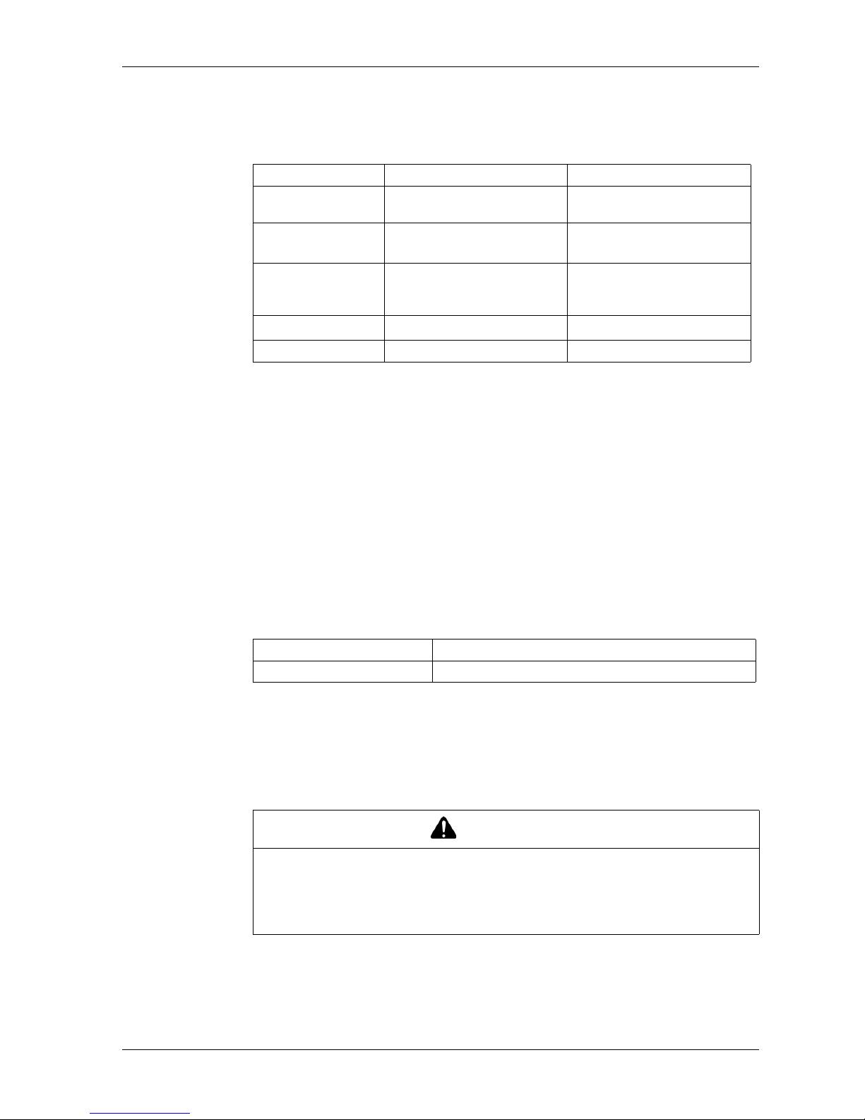
Memory
Clock
Uses the clock of an external device.
Set up the “Clock Updates” feature with the Editor software. Please refer to the GPPro EX Reference Manual “Common” - “Clock Update Settings” for details.
Touch Panel
The GP-4201TM and GP-4301TM touch panel does not support two point touch
(multiple point touch). If you touch multiple points on the touch panel, it will operate
as if you touched the center-point of the multiple touches.
For example, if you touch two or more points on the touch panel and at the center of
the touches is a switch for a drive system, even though you did not directly touch
that switch, it may function as if you did.
GP-Pro EX Ver.3.01 or earlier GP-Pro EX Ver.3.1 or later
Application Memory
*1
*1. Capacity available for user application.
FLASH EPROM 8 MB FLASH EPROM 8 MB (including
a logic program area)
Logic Program Area None
FLASH EPROM 132 KB
*2
(Equivalent to 15,000 steps)
*2. Up to 60,000 steps can be converted in software. However, this re-
duces application memory capacity (for screen data) by 1 MB.
Font Area None FLASH EPROM 8 MB
(when limit exceeded, uses
application memory)
Data Backup
FLASH EPROM 128 KB
*3
*3. Stores the Alarm History Data, Recipe Data, and Brightness/Contrast
Control Settings.
NVSRAM 128 KB
Variable Area None None
Touch Panel Type Resistive Film (analog)
Touch Panel Service Life 1 million times or more
WARNING
UNINTENDED OPERATION
Do not simultaneously touch two or more points on the GP-4201TM, GP-4301TM.
Failure to follow these instructions can result in death, serious injury, or
equipment damage.
Page 33
Specifications
33
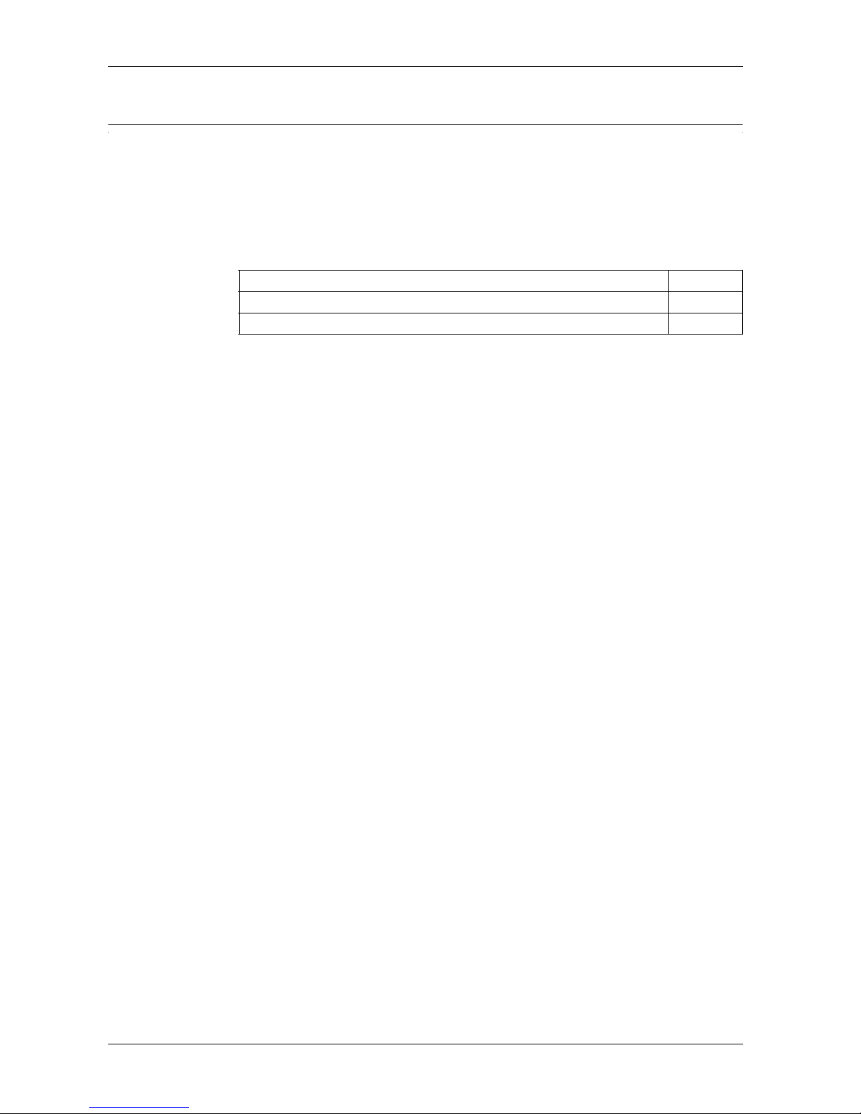
3.3 Interface Specifications
Overview
This section presents the interface specifications of the GP unit.
What's in this Section?
This section contains the following topics:
Topic Page
Interface Specifications 34
Specifications of Serial Interface COM1 35
Page 34
GP-4201TM/4301TM/4000M Hardware Manual
34
Interface Specifications
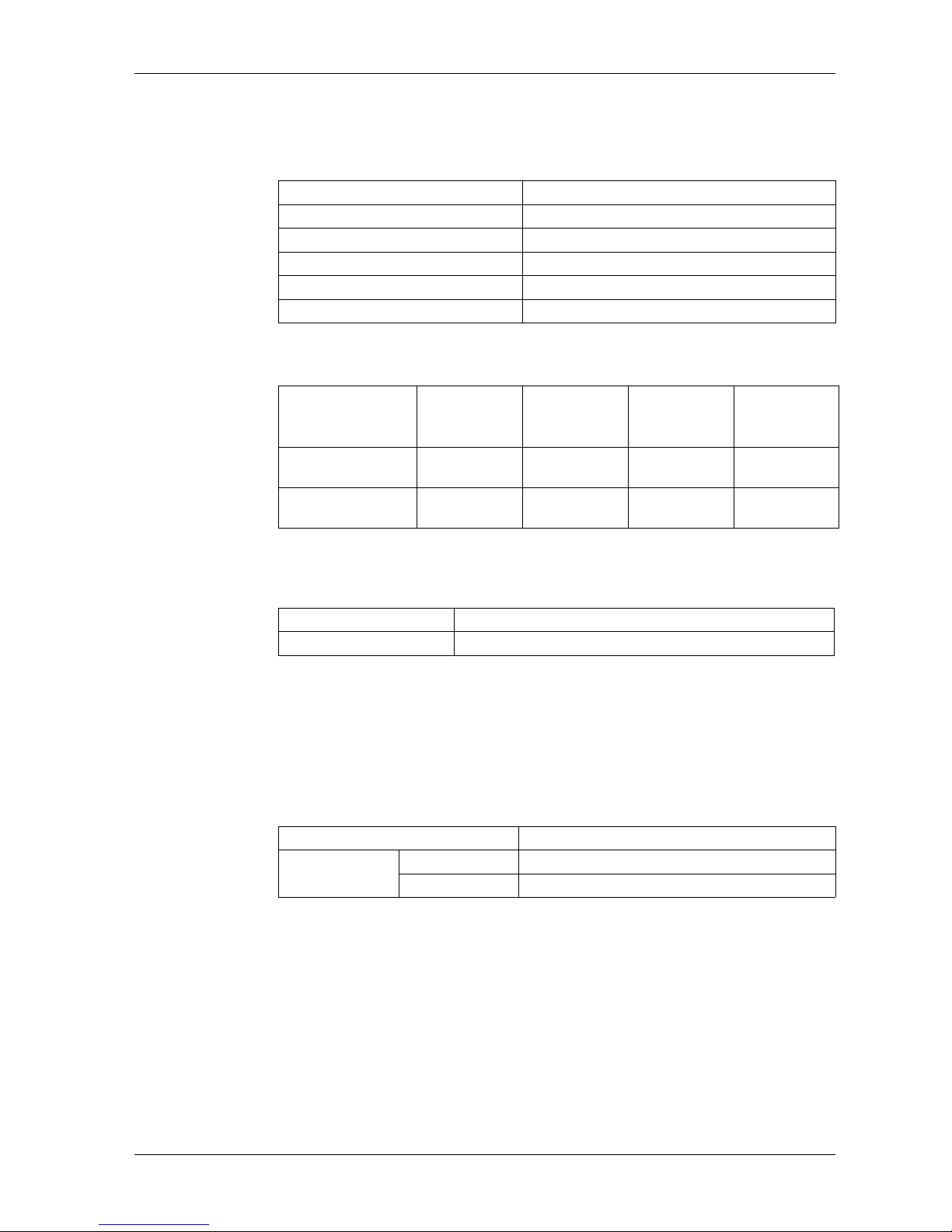
Serial Interface COM1
USB Interface
Ethernet Interface
NOTE: Ethernet networks must be installed by a trained and qualified person.
When connecting the external device directly to the GP unit with an Ethernet cable,
depending on the external device, communication may not be possible.
Please connect over a network hub.
The following table describes the LED colors and status:
Asynchronous Transmission RS-232C / RS-422 / RS-485
Data Length 7 or 8 bits
Stop Bit 1 or 2 bits
Parity None, odd or even
Data Transmission Speed 2,400...115.200 kbps, 187,500 bps
Connector D-Sub 9 pin (plug)
Connector Power Supply
Voltage
Maximum
Current
Supplied
Maximum
Transmission
Distance
USB (Type A)
Interface
USB2.0 (Type
A) x 1
5Vdc
±5%
200 mA 3 m (9.84 ft)
USB (mini-B)
Interface
USB2.0 (miniB) x 1
- - 5 m (16.40 ft)
Ethernet (LAN) IEEE802.3i/ IEEE802.3u, 10BASE-T/100BASE-TX
Connector Modular jack (RJ-45) x 1
LED Contents
Green lit Data transmission is available.
blinking Data transmission is occurring.
Page 35
Specifications
35
Specifications of Serial Interface COM1
Introduction
NOTE: For instructions on how to connect to other devices, always refer to the “GP-
Pro EX Device/PLC Connection Manual”.
The serial port is not isolated. The SG (signal ground) and the FG (frame ground)
terminals are connected inside the unit.
DANGER
ELECTRIC SHOCK
When using the SG terminal to connect an external device to the unit:
Verify that a short-circuit loop is not created when you set up the system.
Connect the #5 SG terminal to remote equipment when the host (PLC) unit is
not isolated. Connect the #5 SG terminal to a known reliable ground connection
to reduce the risk of damaging the circuit.
Failure to follow these instructions will result in death or serious injury.
Page 36
GP-4201TM/4301TM/4000M Hardware Manual
36
Serial Interface COM1
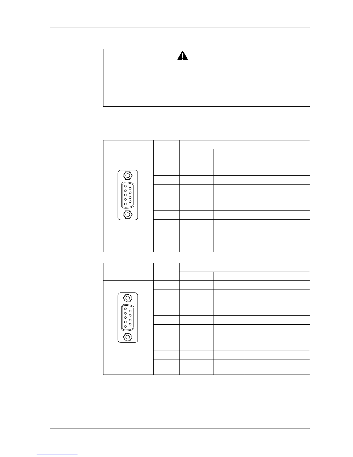
GP-4201TM/4301TM: D-Sub 9 pin plug connector via an RS-232C/RS-422/RS-485
cable.
Interfit bracket is #4-40 (UNC).
CAUTION
LOSS OF COMMUNICATION
All connections to the communication ports must not put excessive stress on the
ports.
Securely attach communication cables to the panel or cabinet.
Failure to follow these instructions can result in injury or equipment damage.
Pin Arrangement Pin No. RS-232C
Signal Name Direction Meaning
1 CD Input Carrier Detect
2 RD(RXD) Input Receive Data
3 SD(TXD) Output Send Data
4 ER(DTR) Output Data Terminal Ready
5 SG - Signal Ground
6 DR(DSR) Input Data Set Ready
7 RS(RTS) Output Request to Send
8 CS(CTS) Input Send Possible
9 CI(RI) Input Called status display
Shell FG - Frame Ground
(Common with SG)
Pin Arrangement Pin No. RS-422/RS-485
Signal Name Direction Meaning
1 RDA Input Receive Data A(+)
2 RDB Input Receive Data B(-)
3 SDA Output Send Data A(+)
4 ERA Output Data Terminal Ready A(+)
5 SG - Signal Ground
6 CSB Input Send Possible B(-)
7 SDB Output Send Data B(-)
8 CSA Input Send Possible A(+)
9 ERB Output Data Terminal Ready B(-)
Shell FG - Frame Ground
(Common with SG)
9
6
5
1
(GP unit side)
9
6
5
1
(GP unit side)
Page 37
Specifications
37
3.4 Dimensions
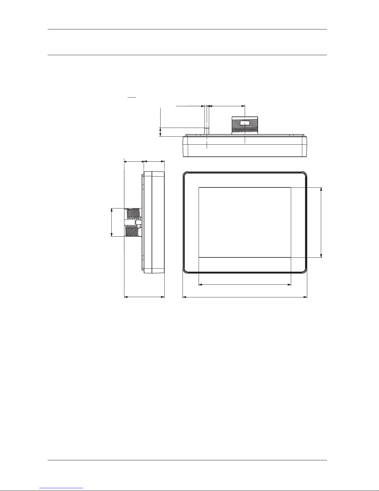
Display Module GP-4201TM
(1) Front
(2) Left Side
(3) Top
72.6
97.6
5
5
Ø 3.43
7.6
30
2.85
3.84
1.18
Ø 0.13
62
.
0
61.2
mm
in.
(1)
(3)
22
Ø
31.5
16.2
0.63
68.0 Ø
1.24
(2)
15.3
0.60
Page 38
GP-4201TM/4301TM/4000M Hardware Manual
38
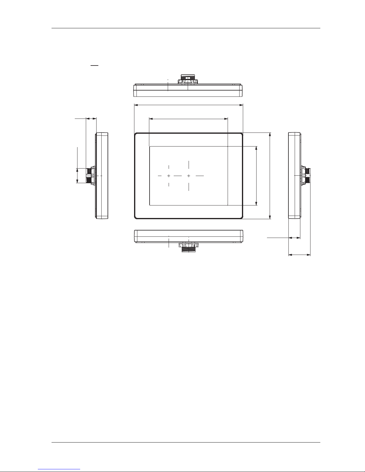
Display Module GP-4301TM
(1) Front
(2) Left Side
(3) Top
(4) Bottom
(5) Right Side
163
6.41
117.7
4.63
4.88
84.3
4.921
9
0
.5
15.3
0.60
Ø
1
.
22
Ø
78.0
17.5
0.69
32.8
1.29
mm
in.
(2) (5)
(1)
(4)
(3)
Page 39
Specifications
39
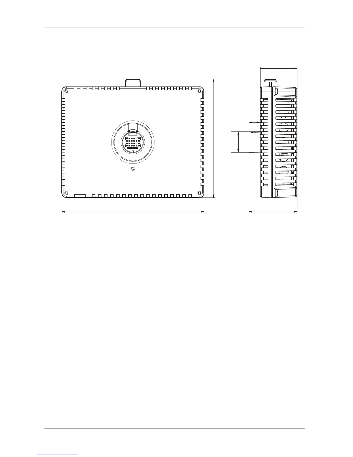
Rear Module (for all GP units)
(1) Front
(2) Right Side
118
1.89
4.64
68.3
(1)
30.6
40.1
2.71
9.5
1.20
0.37
76.0
1.57
(2)
mm
in.
Page 40
GP-4201TM/4301TM/4000M Hardware Manual
40
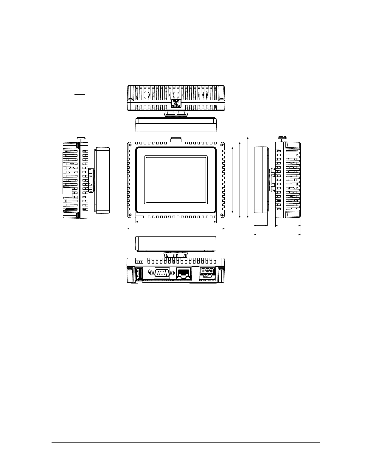
Display and Rear Modules GP-4201TM
(1) Front
(2) Left Side
(3) Top
(4) Bottom
(5) Right Side
97.6
(1)
(3)
3.84
118
4.64
16.2 30.6
0.63
1.20
56.3
2.21
41.3
92
3.62
98.15
3.86
mm
in.
(2) (5)
80
Page 41
Specifications
41
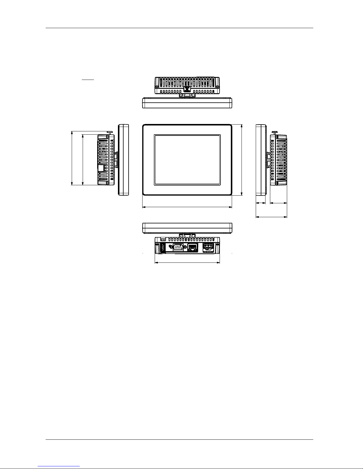
Display and Rear Modules GP-4301TM
(1) Front
(2) Left Side
(3) Top
(4) Bottom
(5) Right Side
mm
in.
(3)
(4)
163
(1)
6.41
118
4.64
129.4
5.094
(2)
(5)
98.15
3.86
92
3.62
17.5
0.69
30.6
1.20
56.5
2.224
Page 42
GP-4201TM/4301TM/4000M Hardware Manual
42
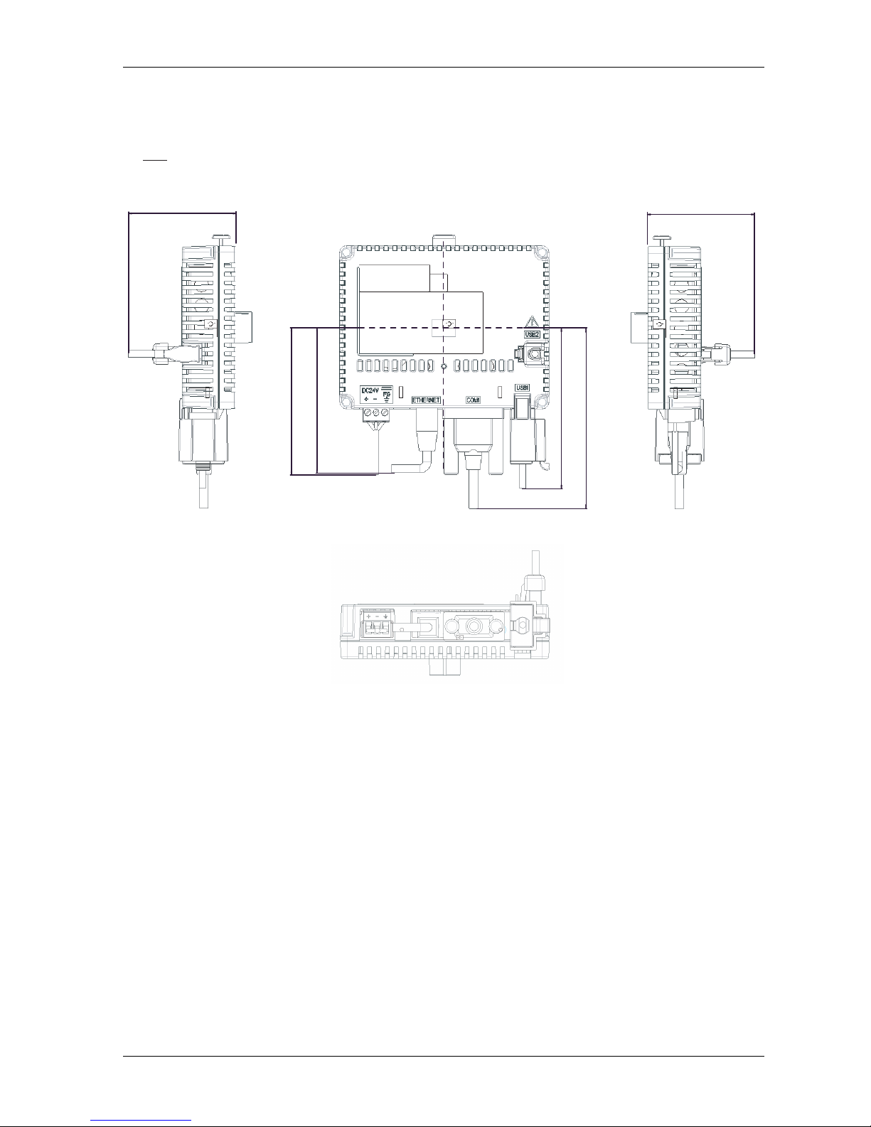
Cable Attached Dimensions
(1) Rear
(2) Left Side
(3) Right Side
(4) Bottom
NOTE:
All the above values are designed in case of cable bending. The dimensions given here
are representative values depending on the type of connection cable used.Therefore, they
are all intended for reference only.
60.4
(2) (1) (3)
(4)
82
3.23
90.8
3.57
102
4.02
80
3.15
mm
in.
2.38
60.4
2.38
Page 43
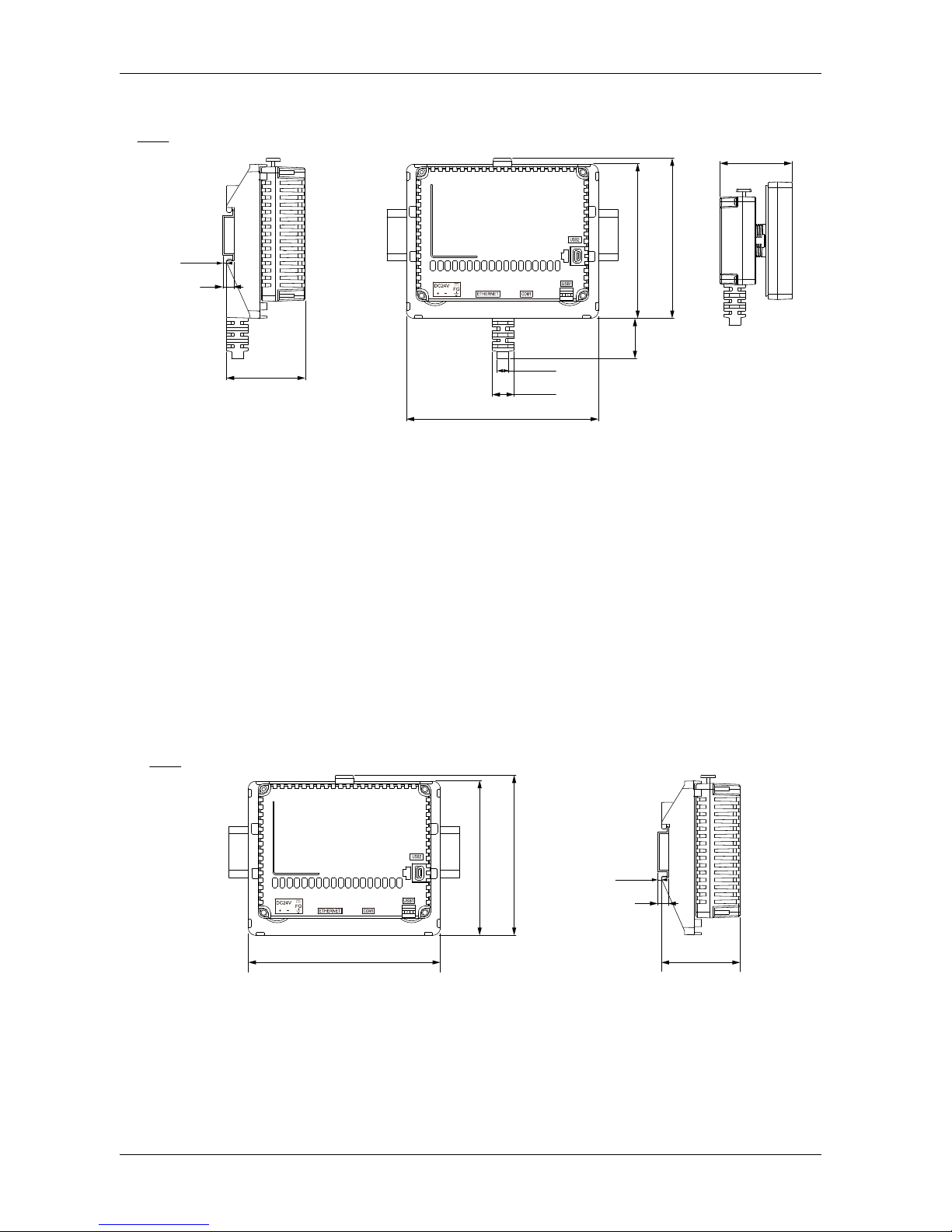
Specifications
43
Separation Cable Attached Dimension
(1) Rear
(2) Left Side
(3) Right Side
NOTE:
Use this display module/rear module separation cable when the rear module is installed
on a DIN rail:
The outer diameter of the cable is 8 mm (0.31 in).
There are 2 types of cable: 3 m (9.84 ft) and 5 m (16.4 ft).
To assemble this product, you need 20 mm (0.78 in) more space to bend the
cable in the end of the rubber.
DIN Rail Attached Demention
(1) Rear
(2) Left Side
(2)
(3)
48,9±0,5
1.9±0.02
mm
in.
53.9±0,5
2.12±0.02
2,5±0,3
0.1±0.01
7,5
0.3
131,35±0,4
5.17±0.016
14.5±0,2
0.57±0.008
8±0,3
0.31±0.012
27,3±0,5
1.07±0.02
105,35±0,4
4.15±0.016
109,83±0,4
4.32±0.016
DIN Rail
DIN Rail
(2)
mm
in.
53.9±0,5
2.12±0.02
2,5±0,3
0.1±0.01
7,5
0.3
131,35±0,4
5.17±0.016
105,35±0,4
4.15±0.016
109,83±0,4
4.32±0.016
DIN Rail
DIN Rail
Page 44

GP-4201TM/4301TM/4000M Hardware Manual
44
Page 45
45
Installation and Wiring
4
EIO0000000614 07/2010
Installation and Wiring
Overview
This chapter describes the installation procedures and the wiring principles for GP
unit.
What's in this Chapter?
This chapter contains the following sections:
Section Topic Page
4.1 Installation 46
4.2 Wiring Principles 57
4.3 USB Interface 64
Page 46
GP-4201TM/4301TM/4000M Hardware Manual
46
4.1 Installation
Overview
This section describes the installation Procedures for GP unit.
What's in this Section?
This section contains the following topics:
Topic Page
Panel Cut-out Dimensions and Installation 47
Installation Procedures 51
Page 47
Installation and Wiring
47
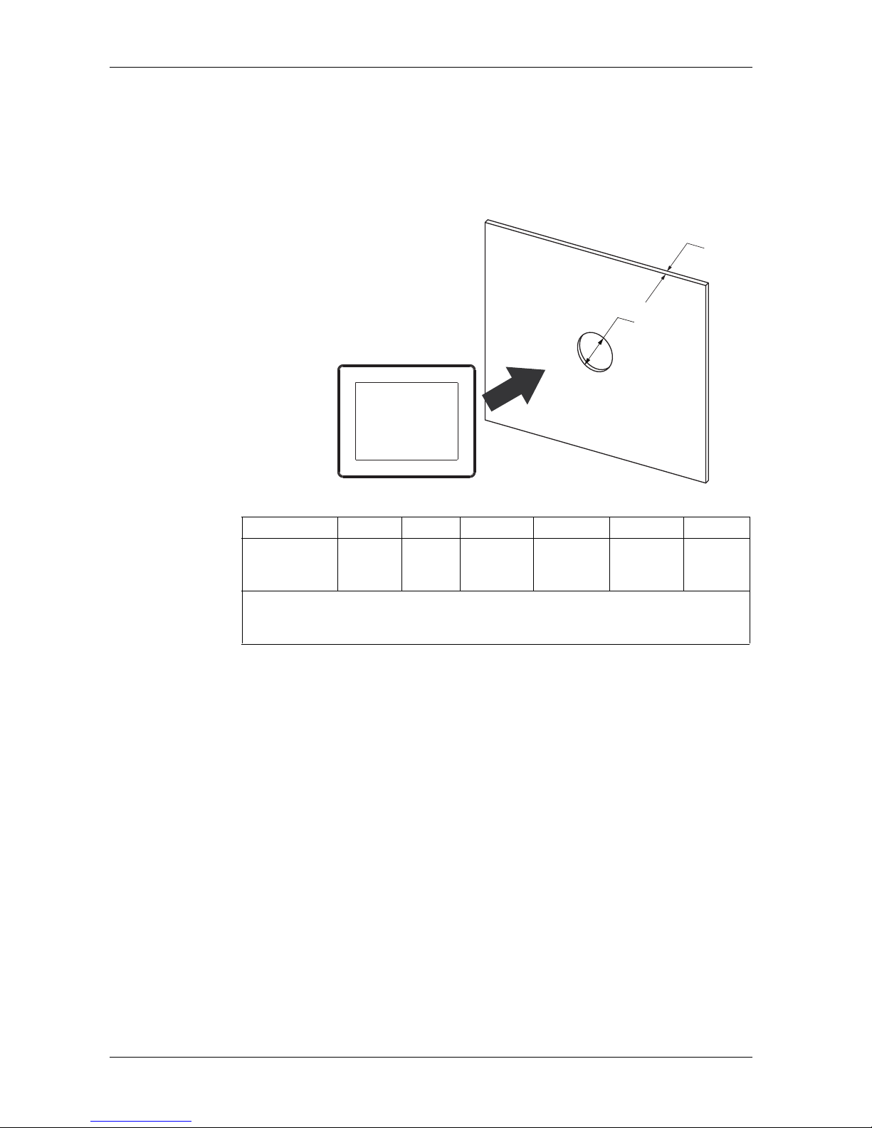
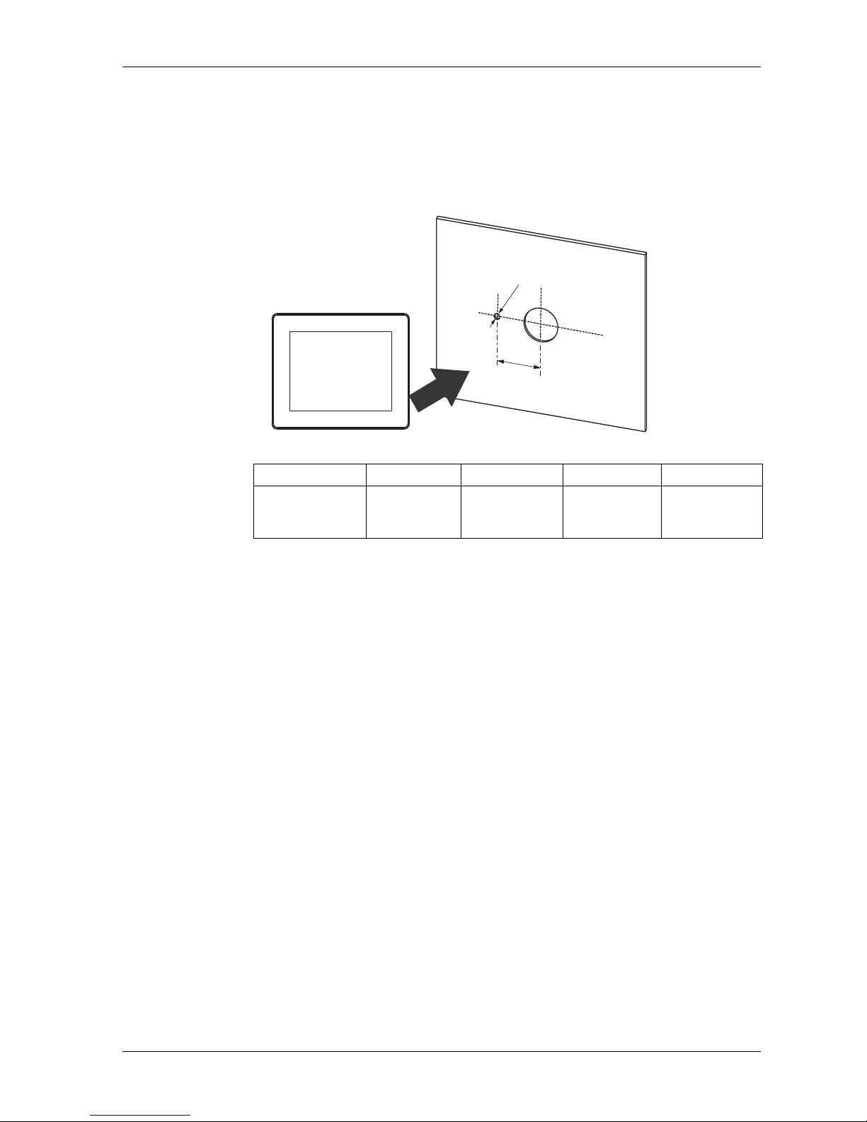
Panel Cut-out Dimensions and Installation
Inserting a GP unit Without an Anti-rotation Tee
Create a panel cut-out and insert the display module of the unit into the panel from
the front. The following illustration shows the panel cut-out for a GP unit without a
tee:
Dimensions
NOTE: Without the tee option, the rotating torque that can be supported by the
display module is 2.5 N•m (22.12 in-lb).
Unit A (mm) A (in) B (mm) (1) B (in) (1) B (mm) (2) B (in) (2)
GP-4201TM
GP-4301TM+022.50
-0.30
+0
0.88
-0.01
1.5 to 6 0.06 to 0.23 3 to 6 0.11 to
0.23
The Material of the panel
(1) Steel sheet
(2) Glass fiber reinforced plastics (minimum GF30)
A
B
Page 48
GP-4201TM/4301TM/4000M Hardware Manual
48
Inserting a GP unit With an Anti-rotation Tee
NOTE:
An Anti-rotation Tee is included in the package. It's appropriate for installing the GP
unit horizontally into the panel.
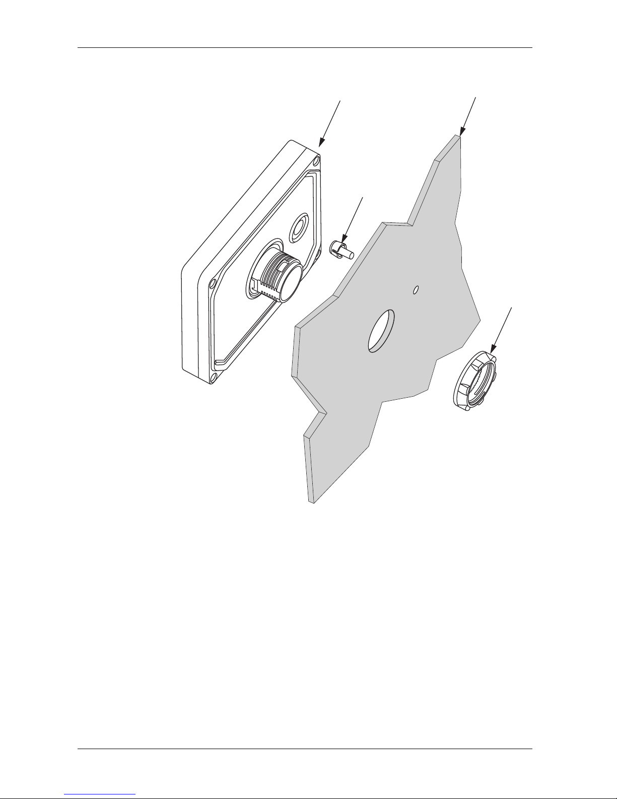
Create a panel cut-out and insert the display module of the unit into the panel from
the front. The following illustration shows the panel cut-out for a GP unit using a tee:
Dimensions
NOTE: With the tee option, the rotating torque is 6 N•m (53.10 in-lb).
Unit C (mm) C (in) D (mm) D (in)
GP-4201TM
GP-4301TM
+0
30.00
-0.20
+0
1.18
-0.007
+0
4.00
-0.20
+0
0.15
-0.007
D
C
Page 49
Installation and Wiring
49
Illustration
(1) Display module
(2) Panel
(3) Display Installation Nut
(4) Anti-rotation tee
(4)
(1) (2)
(3)
Page 50
GP-4201TM/4301TM/4000M Hardware Manual
50
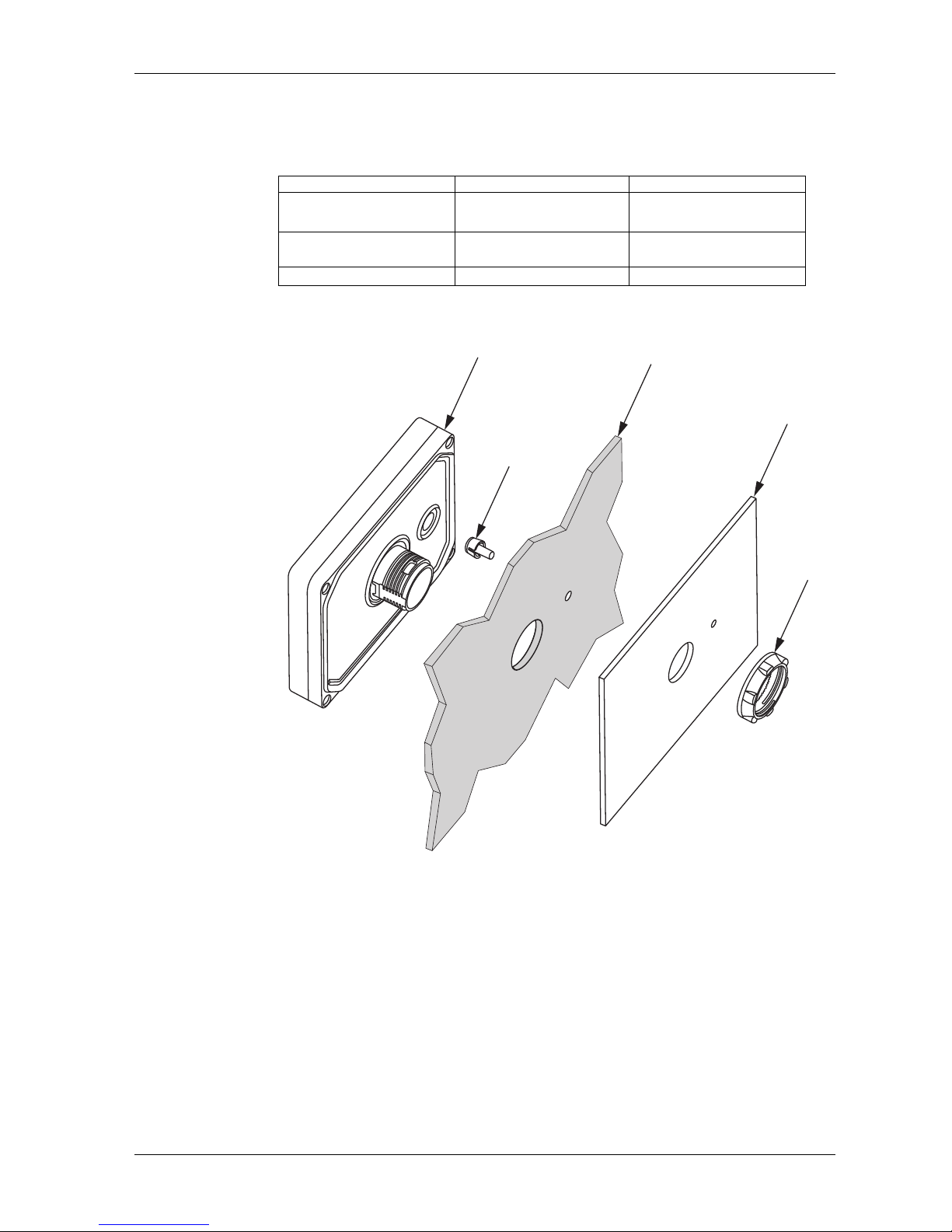
2mm-hight spacer
The Spacer, supplied in the Accessories kit (sold separately) (see page 26), allows
mounting the product on a following panel.
The following illustration shows the assembly with the panel adaptor:
(1) Display module
(2) Panel
(3) Panel adaptor
(4) Display Installation Nut
(5) Anti-rotation tee
Material GP-4201TM GP-4301TM
Steel sheet
1 to 1.5 mm (0.04 and
0.06 in)
1 to 1.5 mm (0.04 and
0.06 in)
Glass fiber reinforced plastics (minimum GF30)
1 to 3 mm (0.04 to 0.12 in) 2 to 3 mm (0.08 to 0.12 in)
Other plastic
1 to 3 mm (0.04 to 0.12 in)
not possible
(5)
(1)
(2)
(4)
(3)
Page 51
Installation and Wiring
51
Installation Procedures
NOTE:
When transporting a panel with a GP installed, remove its rear module. The stress
from cables connecting peripheral equipment may cause damage to GP connectors.
Even though the GP may still be under warranty, damage caused by transporting a
panel with the GP rear module installed can be repaired for a fee.
Panel Setup Procedure
Mount the unit in an enclosure that provides a clean, dry, robust and controlled
environment (IP65f enclosure or UL508 4x, if indoors.) (see page 28)
Before installing the GPunit verify that:
The gasket is flat and not damaged.
The installation panel or cabinet surface is flat (planarity tolerance: 0.5 mm
(0.019 in), in good condition and has no jagged edges. Metal reinforcing strips
may be attached to the inside of the panel, near the panel cut-out, to increase the
rigidity.
The panel must be designed to avoid any induced vibration resonance on the rear
module exceeding a punctual factor of 10 and to avoid any induced permanent
vibration resonance.
To reduce the resonance use the spacer supplied in the Accessories kit (sold
separately).
The ambient operating temperature and the ambient humidity are within their
specified ranges (see page 28).
The heat from surrounding equipment does not cause the unit to exceed its
specified operating temperature (see page 28).
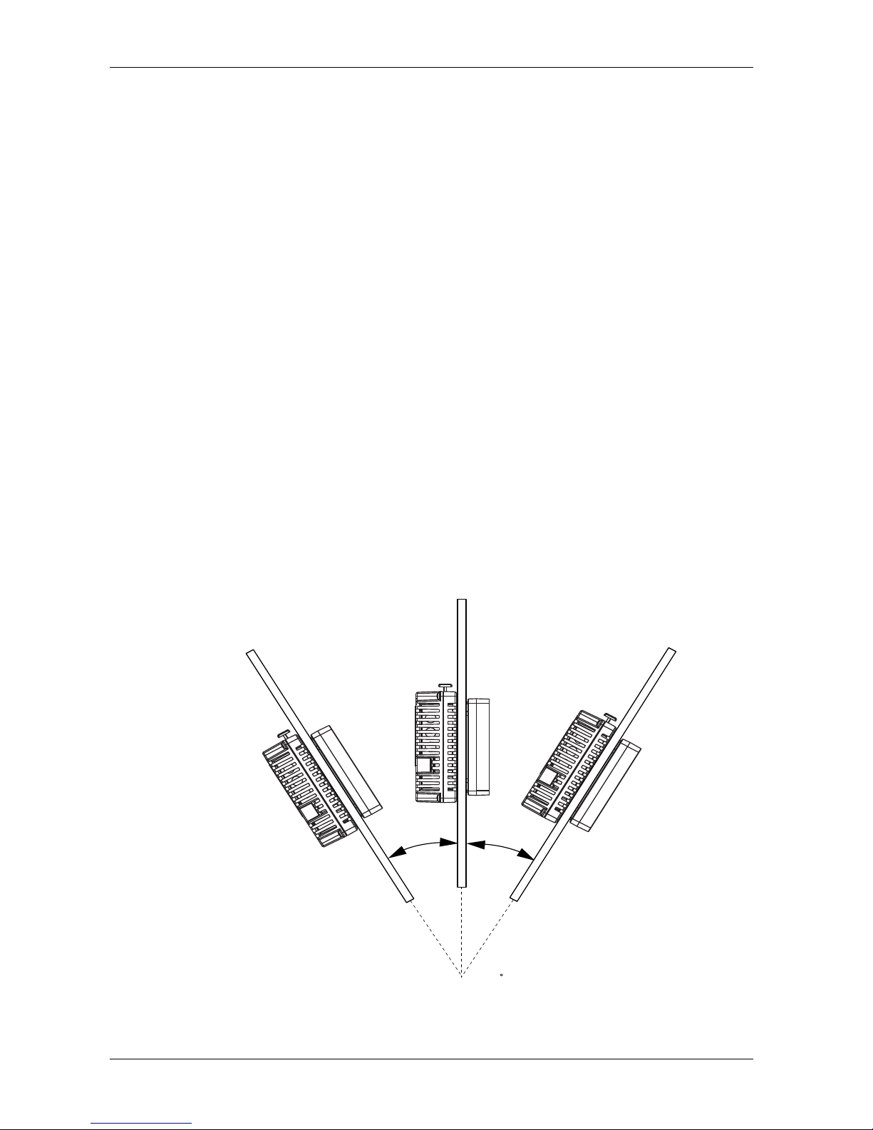
The panel face is not inclined more than 30 when installing the unit in a slanted
panel:
30 or less
Page 52
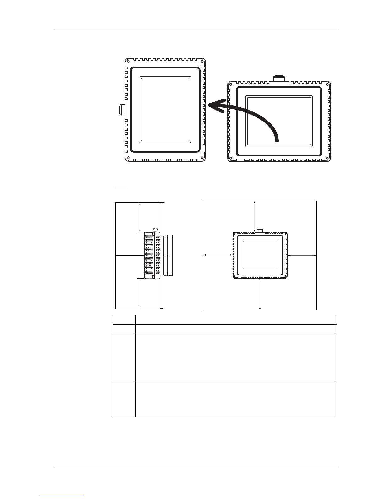
GP-4201TM/4301TM/4000M Hardware Manual
52
When mounting the GP unit vertically, ensure that the right side of the unit faces
up (i.e. the yellow button should be at the left).
The unit is at least 100 mm (3.94 in) away from adjacent structures and other
equipment for easier maintenance, operation and improved ventilation:
Step Action
1 Place the unit on a clean and level surface with the display panel facing downward.
2 The support thickness depends on the material:
Steel: 1.5 to 6 mm (0.06 to 0.23 in)
Glass fiber reinforced plastics (minimum GF30): 3 to 6 mm (0.11 to 0.23 in)
If the panel thickness is less than the above values, use the spacer in Accessories
kit (sold separately). For the panel thickness and materials when using the spacer,
please refer to "2 mm-hight spacer" (see page 50).
3
Create the correct sized holes required to install the unit, using the Panel Cut-out
Dimension and Installation (see page 47).
NOTE:
The field wiring opening for controller when mounted onto an enclosure shall
have an area of not more than 775 mm
2
(1.2 in2).
100
3.94
001
49.3
001
49.3
001
4
9
.3
0
0
1
49.3
100
3.94
100
39.4
mm
in.
Page 53
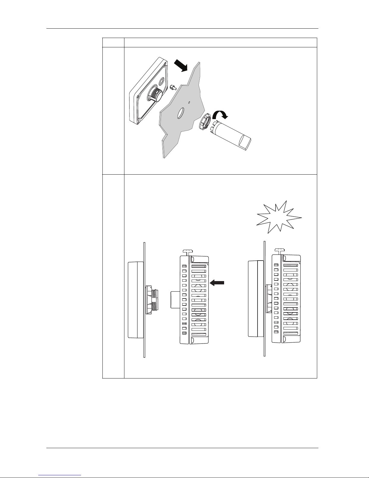
Installation and Wiring
53
4 Insert the display module (with Tee, if used) into the panel hole:
Screw the nut with the socket wrench with a torque between 1.2 and 2 N•m (10.62
and 17.70 in-lb).
5 Insert and push the rear module until it locks into place:
NOTE: Install the display module and the rear module in the orientation shown in
the illustration. If either unit is installed incorrectly, the connector may be damaged.
Step Action
Click
Insert and
push
Free Locked
Page 54
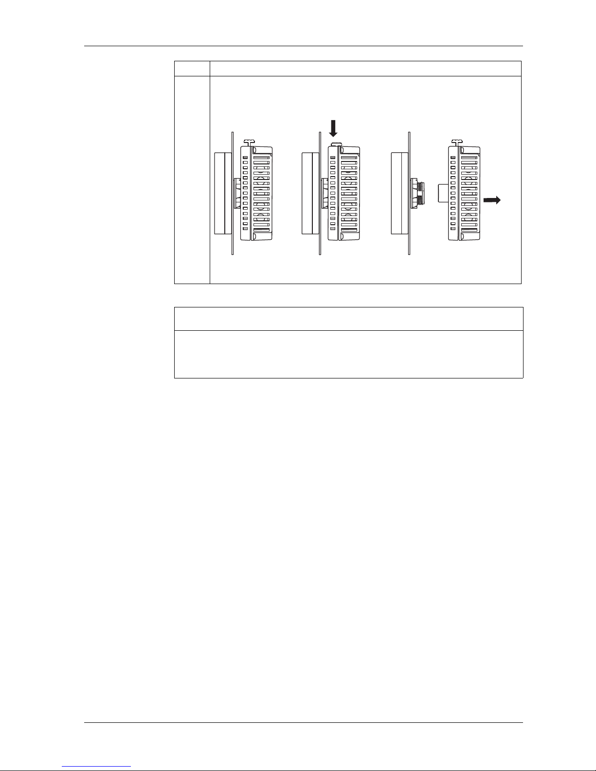
GP-4201TM/4301TM/4000M Hardware Manual
54
6 To remove the rear module, push the yellow button to unlock it, then pull the rear
module out:
NOTICE
EQUIPMENT DAMAGE
Be sure to remove the rear module from the display module without twisting.
Failure to follow these instructions can result in equipment damage.
Step Action
Push
Pull
Locked
Unlocked
Free
Page 55
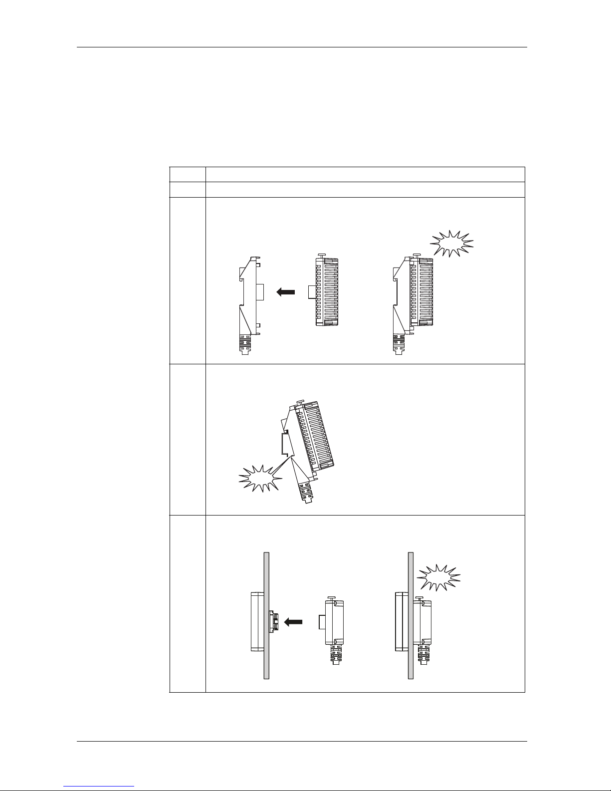
Installation and Wiring
55
Installing and Removing the Rear Module on a DIN Rail
This section describes how to install and remove the rear module on a DIN rail.
NOTE:
Attach front module and rear module both when you use a display module/rear
module separation cable.
Installing the Rear Module on a DIN Rail
Step Action
1 Using screws, to fasten the DIN rail to a panel surfaces.
2 Affix the display module/rear module separation cable or the rear module
installation adapter to the rear module.
3
Position the top groove of the rear module on the top edge of the DIN rail and press the
assembly against the DIN rail until you hear the DIN rail clip click into place.
4 Install the display on the cabinet and affix the display module/rear module
separation cable to the display.
Rear Module
Click!
Click!
DIN Rail
Display
Module
Click!
Display module/Rear module
separation cable
Page 56
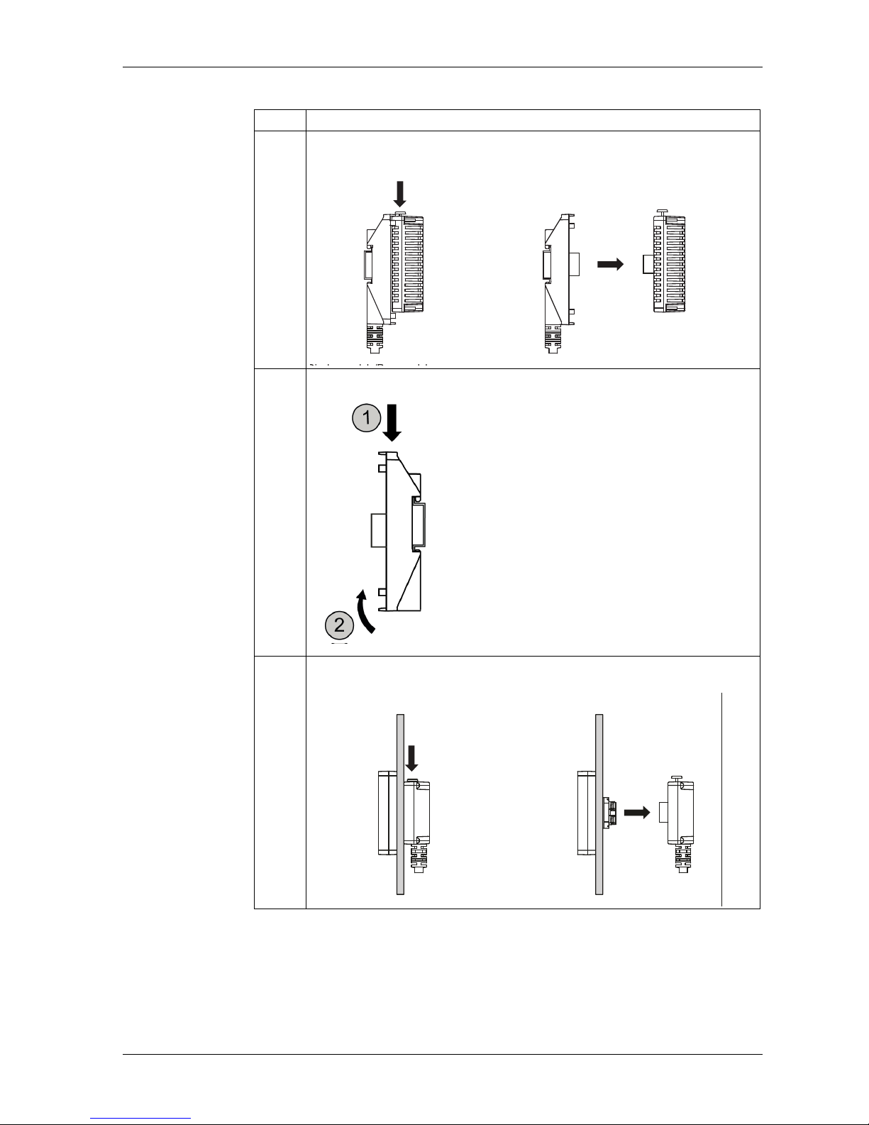
GP-4201TM/4301TM/4000M Hardware Manual
56
Removing the Rear Module from a DIN Rail
Step Action
1 To remove the rear module, push the yellow button to unlock it, then pull the rear
module out.
2 Remove the display module/rear module separation cable from the DIN rail..
3
Remove the display module/rear module separation cable and display module from a
panel..
Rear Module
Click!
DIN Rail
Display
Module
Display module/Rear module
separation cable
Page 57
Installation and Wiring
57
4.2 Wiring Principles
Overview
This section presents GP unit wiring principles.
What's in this Section?
This section contains the following topics:
Topic Page
Connecting the Power Cord 58
Connecting the Power Supply 60
Grounding 62
Page 58
GP-4201TM/4301TM/4000M Hardware Manual
58
Connecting the Power Cord
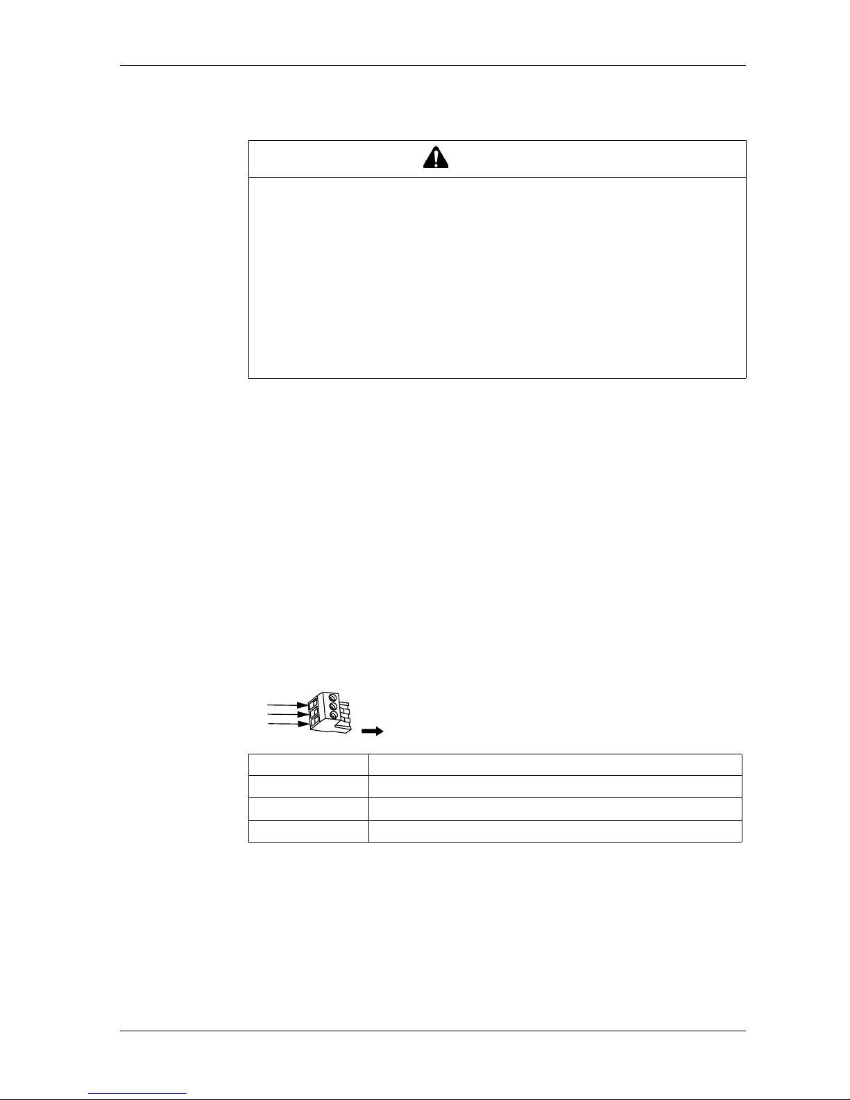
NOTE:
The shield ground (SG) and FG terminals are connected internally in the unit.
Power Cord Preparation
Before using your power cord:
Verify the ground wire is the same gauge or heavier than the power wires.
Do not use aluminum wires for the power cord for power supply.
If the conductor end (individual) wires are not twisted correctly, the end wires may
either short loop to each other or against an electrode. To avoid this, use
D25CE/AZ5CE cable ends.
Use wires that are 0.75 to 2.5 mm
2
(AWG 18 -12) for the power cord, and twist
the wire ends before attaching the terminals.
The conductor type is solid or stranded wire.
To reduce electromagnetic noise, make the power cord as short as possible.
DC Power Supply Connector Illustration
WARNING
HAZARD OF ELECTRIC SHOCK
When the frame ground (FG) terminal is connected, verify the wire is grounded.
Not grounding the unit can result in excessive Electromagnetic Interference
(EMI). Grounding is required to meet EMC level immunity.
Remove power before wiring to the power terminals of the unit.
The unit uses only 24 Vdc power. Using any other level of power can damage
both the power supply and the unit.
Since there is no power switch on the GP unit, be sure to attach a breaker-type
switch to its power cord.
Failure to follow these instructions can result in death, serious injury, or
equipment damage.
Connection Wire
+
24 V
-
0V
FG Grounded terminal connected to the unit chassis
+
-
FG
,QVHUWLRQ
'LUHFWLRQ
Page 59
Installation and Wiring
59
How to connect the Power Cord
The following table explains how to connect the DC power supply connector:
NOTE:
Do not solder the wire directly to the power receptable pin.
The power supply cord must meet the specification shown above. Twist the
power cords together, up to the DC power supply connector, for EMC
cancellation. (See illustration as shown below).
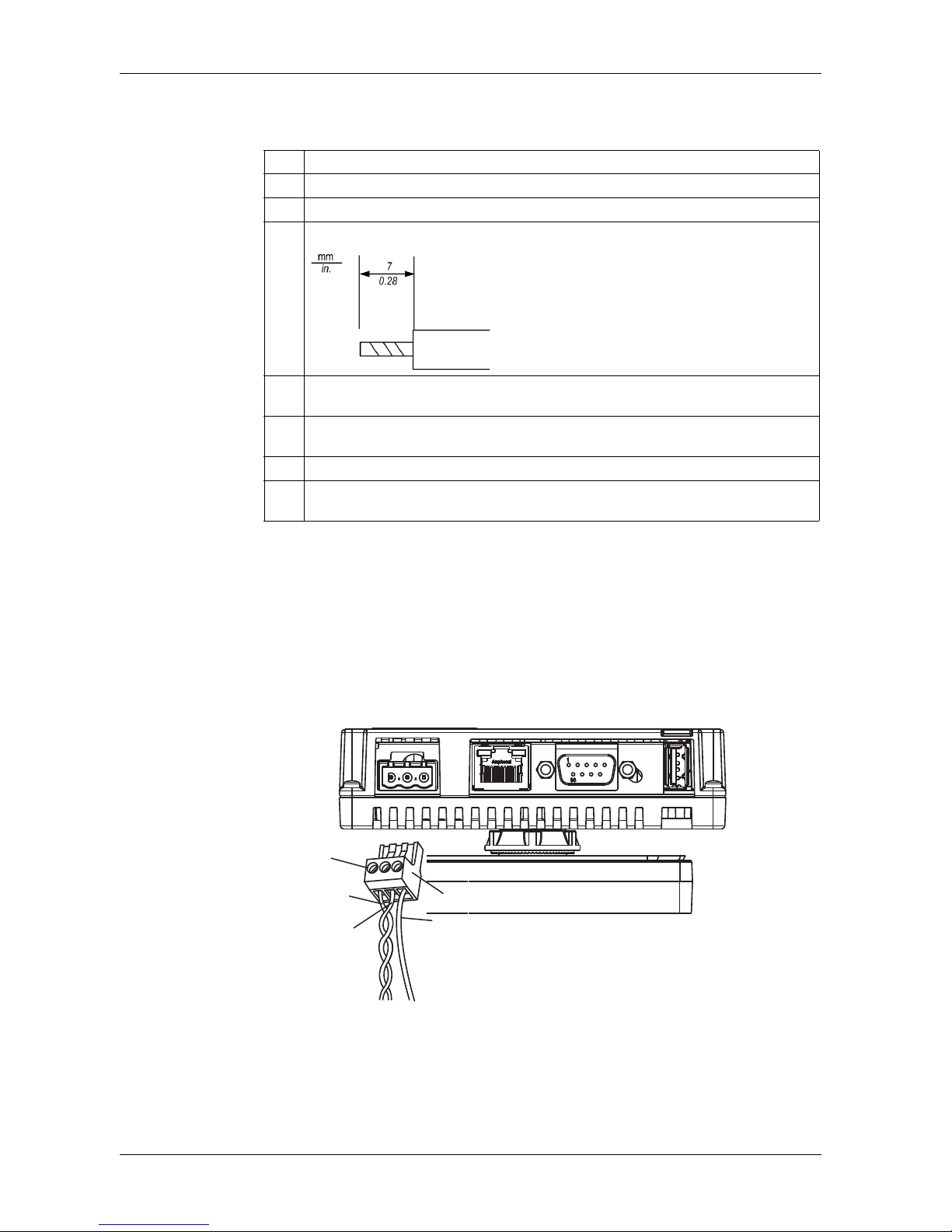
Power Connection
The following illustration displays a connection of the power cord:
Step Action
1 Remove the power cord from the power supply.
2 Remove the DC power supply connector from the unit.
3
Remove 7 mm (0.28 in) of the vinyl cover of each of the power cord wires.
4 If using stranded wire, twist the ends. Tinning the ends with solder reduces the risk of
fraying and enhances electrical transfer.
5 Connect the wires to the DC power supply connector by using a flat-blade screwdriver
(Size 0.6 x 3.5).
6 Torque the mounting screws: 0.5 to 0.6 N•m (4.4 to 5.2 lb-in).
7 Replace the DC power supply connector to the power connector on the side of the
unit.
+
-
FG
DC power supply connector
Terminal block
wire set block
Page 60
GP-4201TM/4301TM/4000M Hardware Manual
60
Connecting the Power Supply
Precautions
Connect the power cord to the power connector on the side of the unit using the
DC power supply connector.
Use a regulated power supply with a Class 2 power supply between the line and
the ground.
Do not bundle the power supply cord with, or keep close to, main circuit lines
(high voltage, high current), or input/output signal lines.
Connect a lightning surge absorber to handle power surges.
Excessive stress on the power connection or attempting to install a unit with the
power cables connected may disconnect or cause damage to the power
connections. This can cause short circuits, fire or unintended equipment operation.
WARNING
SHORT CIRCUITS, FIRE, OR UNINTENDED EQUIPMENT OPERATION
Securely attach power cables to the panel or cabinet.
Use the designated torque to tighten the unit terminal block screws.
Install and fasten unit on installation panel or cabinet prior to connecting Power
Supply and Communication lines.
Failure to follow these instructions can result in death, serious injury, or
equipment damage.
Page 61
Installation and Wiring
61
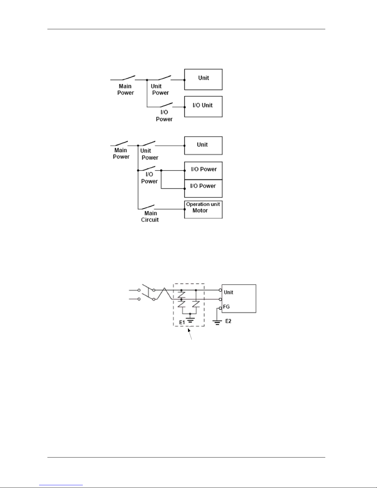
Power Supply Connections
For ease of maintenance, use the following optional connection diagram to set up
your power supply connections.
NOTE:
Ground the surge absorber (E1) separately from the unit (E2).
Select a surge absorber that has a maximum circuit voltage greater than the peak
voltage of the power supply.
The following diagram displays a lightning surge absorber connection:
Lightening Surge Absorber
Page 62
GP-4201TM/4301TM/4000M Hardware Manual
62
Grounding
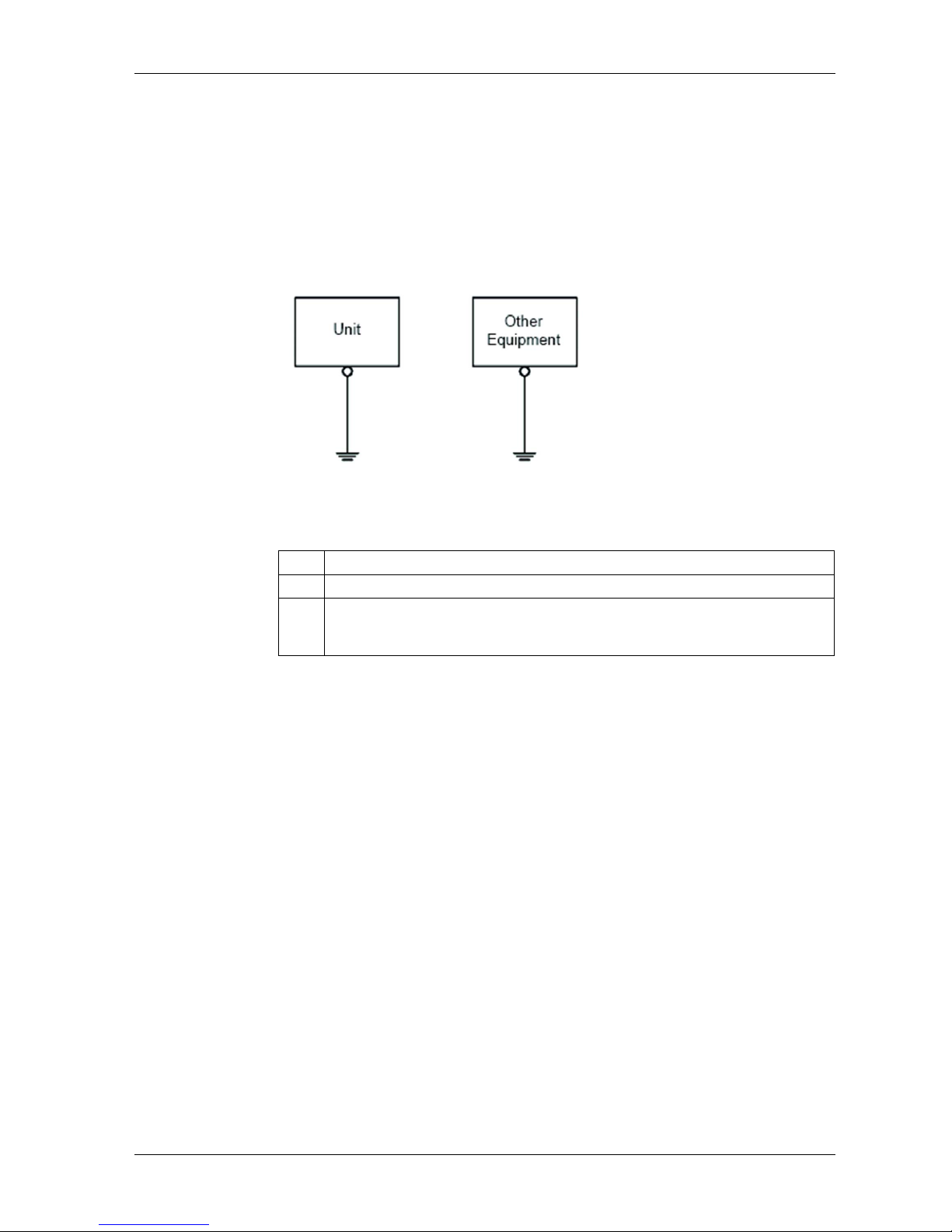
Introduction
Take the following precautions for grounding the unit.
Exclusive Grounding
Connect the frame ground (FG) terminal on the power plug to an exclusive ground.
Grounding Procedure
Step Action
1 Check that the grounding resistance is less than 100 .
2 Create the connection point as close to the unit as possible, and make the wire as
short as possible. When using a long grounding wire, replace the thin wire with a
thicker wire, and place it in a duct.
Page 63
Installation and Wiring
63
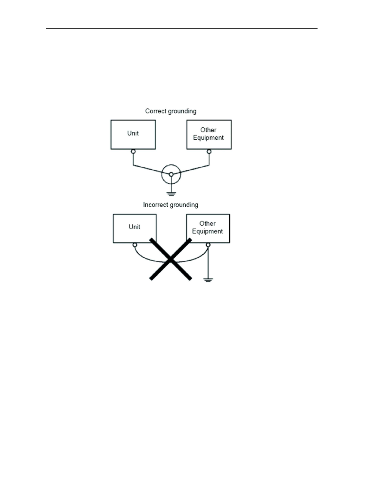
Common Grounding
Precautions:
Electromagnetic Interference (EMI) can be created if the devices are improperly
grounded. Electromagnetic Interference (EMI) can cause loss of communication.
Do not use common grounding, except for the authorized configuration described
below.
If exclusive grounding is not possible, use a common connection point.
Page 64
GP-4201TM/4301TM/4000M Hardware Manual
64
4.3 USB Interface
Overview
This section presents the USB interface.
What's in this Section?
This section contains the following topics:
Topic Page
Important Considerations When Using the USB interface 65
USB Data Transfer Cable (ZC9USCBMB1) - USB Driver Installation 66
USB (Type A) interface 67
USB (mini-B) interface 70
Page 65
Installation and Wiring
65
Important Considerations When Using the USB interface
Introduction
Data transfer cable (ZC9USCBMB1) can be attached to the USB interface to allow
data transfer from the computer to the unit.
WARNING
RISK OF EXPLOSION IN HAZARDOUS LOCATIONS
In hazardous locations as described in ANSI/ISA - 12.12.01:
Confirm that the USB cable has been attached with the USB cable clamp before
using the USB host interface.
Remove power before attaching or detaching any connector(s) to or from the
unit.
Failure to follow these instructions can result in death, serious injury, or
equipment damage.
Page 66

GP-4201TM/4301TM/4000M Hardware Manual
66
USB Data Transfer Cable (ZC9USCBMB1) - USB Driver Installation
Important information
Follow the procedure described below to avoid damage to the cable connector or
the unit:
Do not connect the USB data transfer cable until told to do so in the instructions.
Insert the connector at the correct angle when connecting the USB data transfer
cable to the PC or to the unit.
Hold the connector, not the cable itself when disconnecting the cable.
Use the port designated during installation. If the cable is unplugged from the port
designated during installation and connected to a different port, the OS
(Operating System) will not recognize the new port.
Restart the PC and quit all resident applications before re-installing the software
if the installation does not complete successfully.
NOTE: For transfer methods, refer to the following manual: GP-Pro EX Reference
Manual "Transferring Project Files via USB Transfer Cable".
Page 67
Installation and Wiring
67
USB (Type A) interface
Introduction
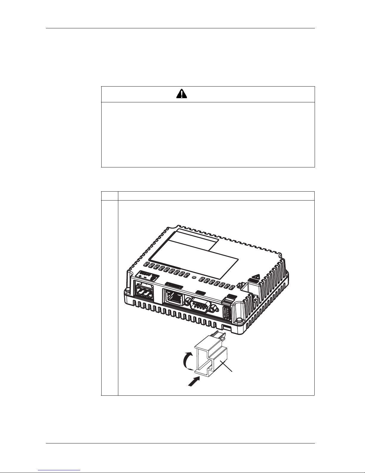
When using a USB device, you can attach a USB clamp to the USB interface to
prevent the USB cable from being disconnected.
Attaching the USB Clamp
WARNING
RISK OF EXPLOSION IN HAZARDOUS LOCATIONS
In hazardous locations as described in ANSI/ISA - 12.12.01:
confirm that the USB cable has been attached with the USB cable clamp before
using the USB host interface.
remove power before attaching or detaching any connector(s) to or from the
unit.
Failure to follow these instructions can result in death, serious injury, or
equipment damage.
Step Action
1 Attach the USB holder to the USB Host Interface on the rear module. Hook the upper
pick of the USB holder to the attachment hole of the main unit, and insert the lower
pick as shown below to fix the USB holder.
(1) USB Holder
(1)
Page 68
GP-4201TM/4301TM/4000M Hardware Manual
68
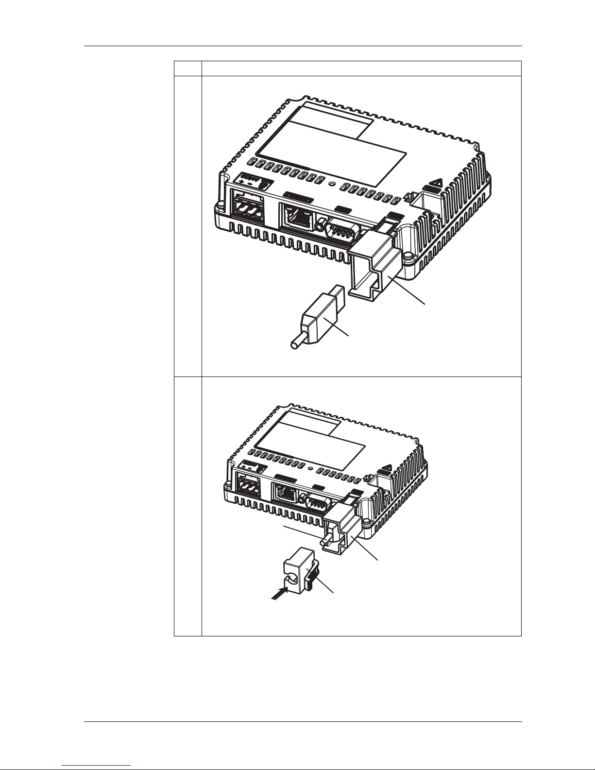
2 Insert the USB cable into the USB host interface.
(1) USB Holder
(2) USB Cable
3 Attach the USB cover to fix the USB cable in place. Insert the USB cover into the tab
of the USB holder.
(1) USB Holder
(2) USB Cover
(3) USB Cable
Step Action
(2)
(1)
(1)
(3)
(2)
Page 69
Installation and Wiring
69
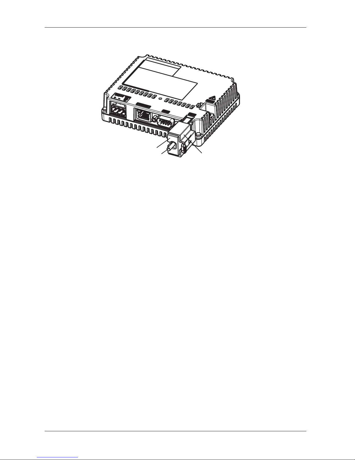
Removing the USB Clamp
Push down the tab of the USB holder and then remove the USB cover.
(1) USB Holder
(2) USB Cover
(3) USB Cable
(1)
(2)
(3)
Page 70
GP-4201TM/4301TM/4000M Hardware Manual
70
USB (mini-B) interface
Introduction
When using a USB device, you can attach a USB holder to the USB interface to
prevent the USB cable from being disconnected.
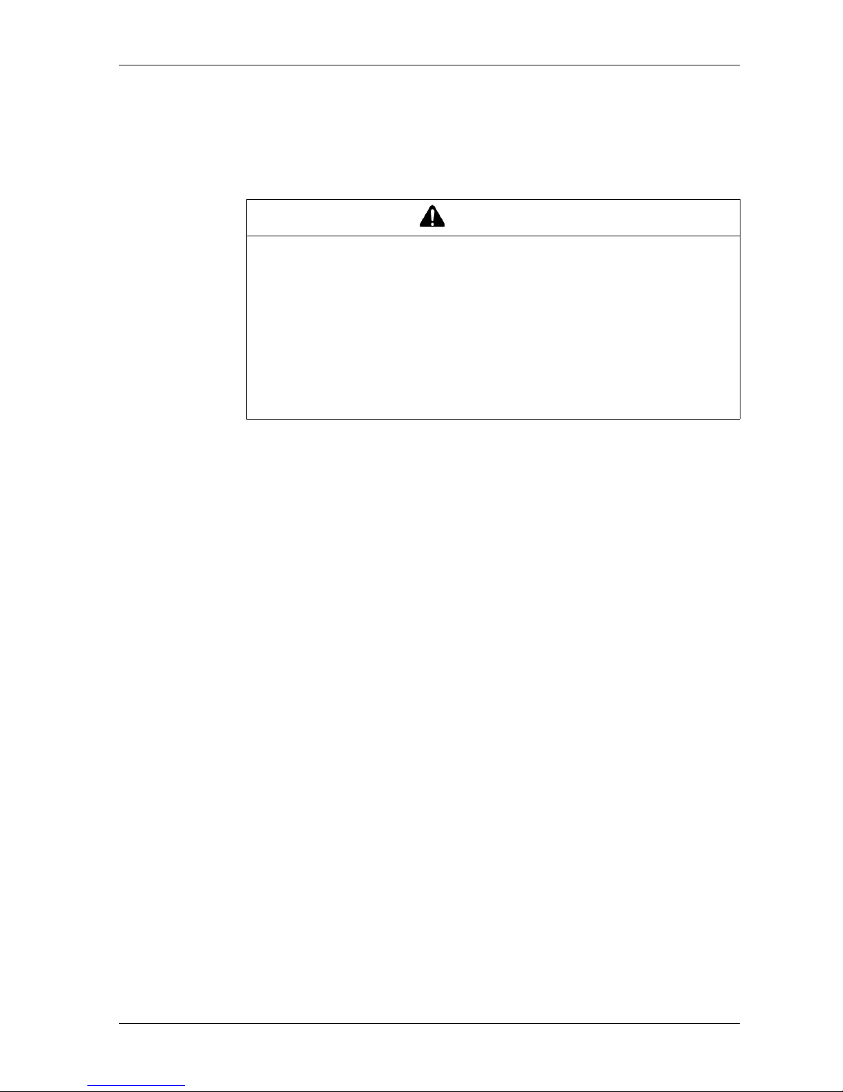
WARNING
RISK OF EXPLOSION IN HAZARDOUS LOCATIONS
In hazardous locations as described in ANSI/ISA - 12.12.01:
The USB mini-B connector is for temporary connection only during maintenance
and setup of the device. Do not use, connect, or disconnect USB mini-B cable
unless area is known to be non-hazardous. Connection or disconnection in an
explosive atmosphere could result in an explosion.
Remove power before attaching or detaching any connector(s) to or from the
unit.
Failure to follow these instructions can result in death, serious injury, or
equipment damage.
Page 71
Installation and Wiring
71
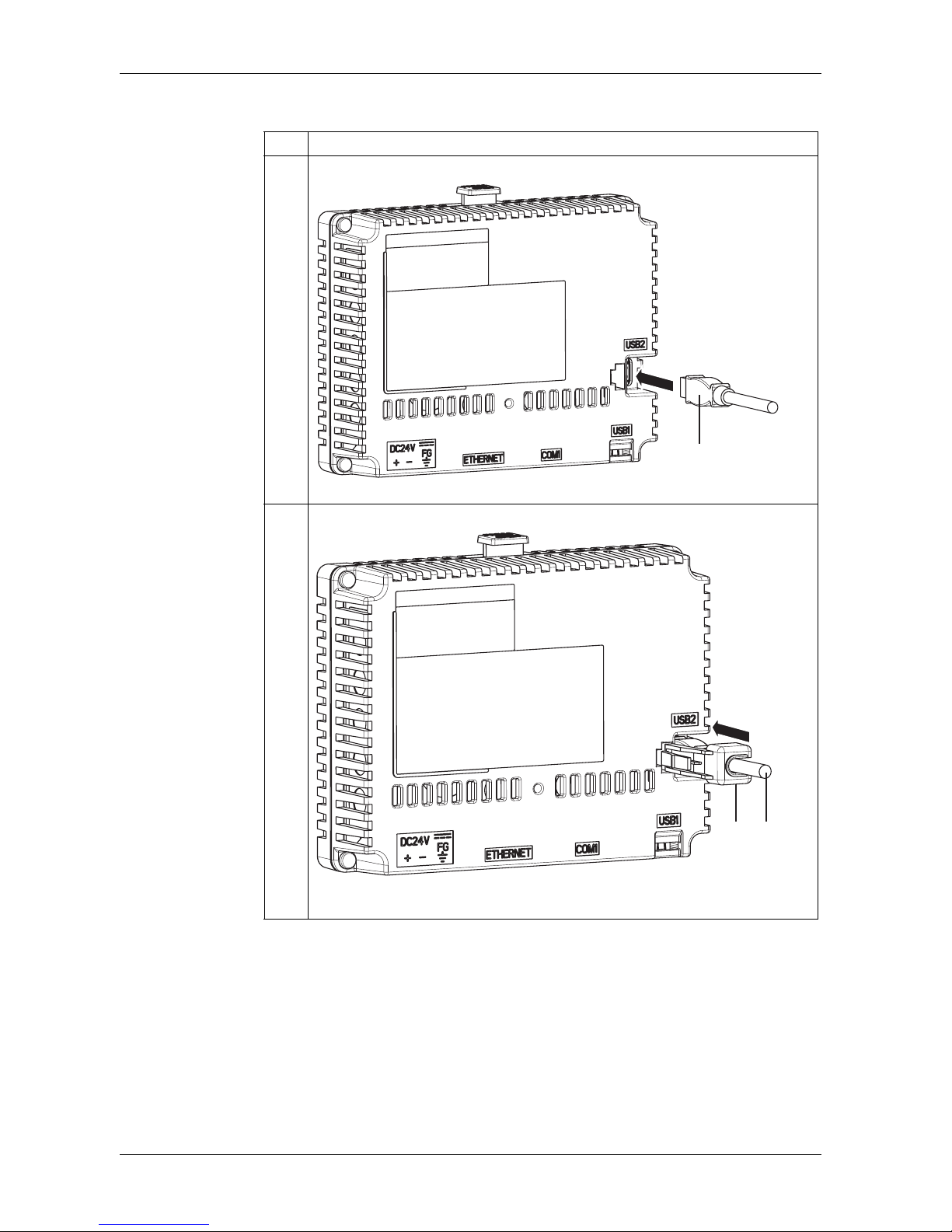
Attaching the USB Clamp
Step Action
1 Insert the USB cable into the USB host interface.
(1) USB Cable
2 Attach the USB holder to fix the USB cable in place.
(1) USB Holder
(2) USB Cable
(1)
(2)
(1)
Page 72
GP-4201TM/4301TM/4000M Hardware Manual
72
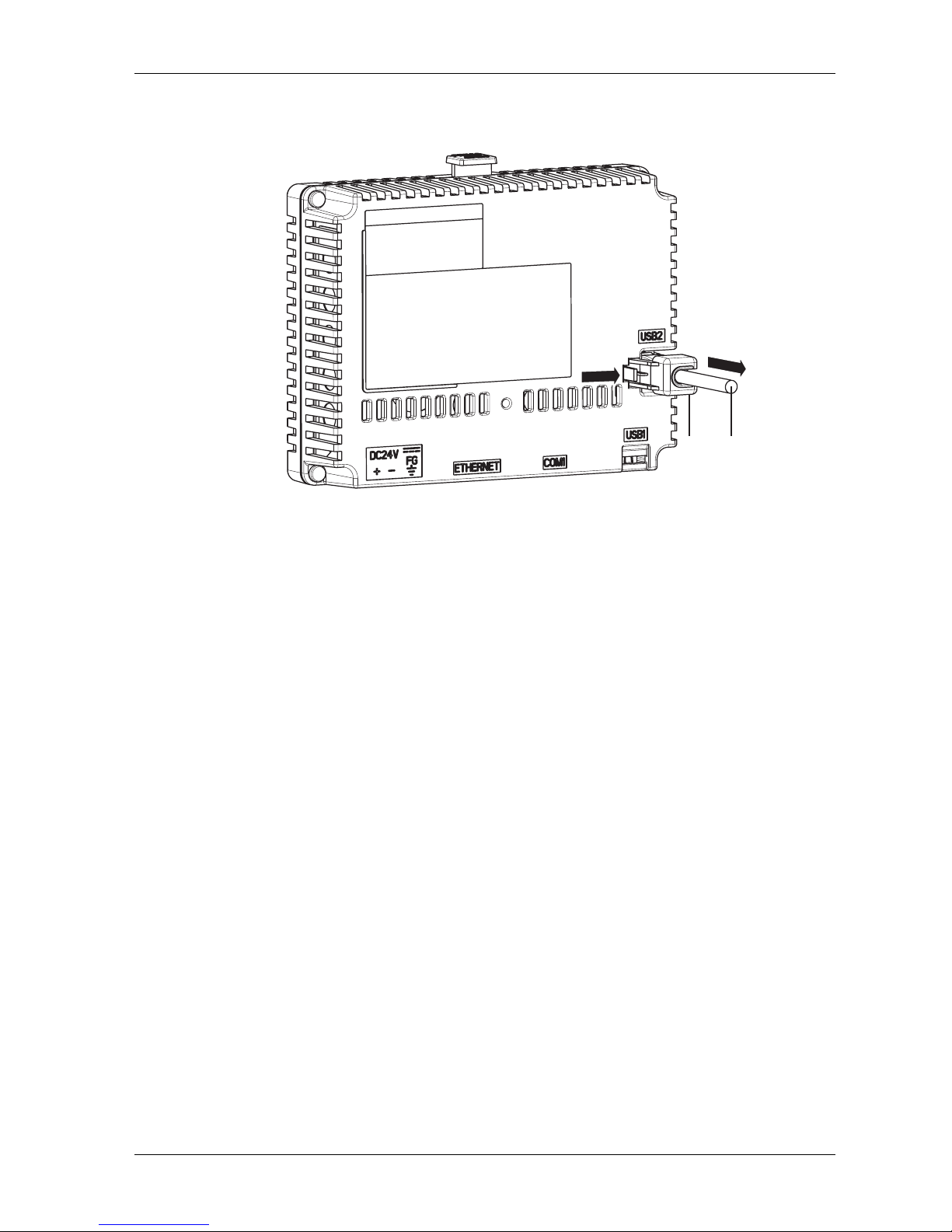
Removing the USB Clamp
Push down the tab of the USB holder and then remove the USB holder.
(1) USB Holder
(2) USB Cable
2
1
(1) (2)
Page 73
73
Maintenance
5
EIO0000000614 07/2010
Maintenance
Overview
This chapter explains how to maintain your GP unit.
What's in this Chapter?
This chapter contains the following topics:
Topic Page
Regular Cleaning 74
Periodic Check Points 74
After-sales service 74
Page 74
GP-4201TM/4301TM/4000M Hardware Manual
74
Regular Cleaning
Cleaning the display
When the surface or the frame of the display gets dirty, soak a soft cloth in water
with a neutral detergent, wring the cloth tightly and wipe the display.
Periodic Check Points
Operation Environment
Refer to the Environmental Specifications (see page 28).
Electrical Specifications
The input voltage must be within 20.4 to 28.8 Vdc.
Related Items
Are all power cords and cables connected properly? Are there any loose cables?
Display Installation Nut holding the unit securely?
Are there scratches or traces of dirt on the installation gasket?
NOTE: A gasket with scratches or dirt could have lost much of its water resistance.
Be sure to change the gasket for water resistance equivalent to IP65f when
scratches or dirt become visible.
After-sales service
For details on after-sales service, refer to Pro-face website at
http://www.pro-face.com/trans/en/manual/1001.html.
NOTICE
EQUIPMENT DAMAGE
Power off the unit before cleaning it.
Do not use hard or pointed objects to operate the touch panel.
Do not use paint thinner, organic solvents, or a strong acid compound to clean
the unit.
Failure to follow these instructions can result in equipment damage.
 Loading...