

Page 1

GP-4100 Series Color Model
Installation Guide
Page 2

3
English
Safety Information
Important Information....................................................................................... 5
Model Numbers
Model Numbers................................................................................................ 7
Global Code ..................................................................................................... 7
Overview
Package Contents............................................................................................ 8
About the Manual............................................................................................. 8
Part Numbers and Functions
Part Numbers and Functions ........................................................................... 9
Specifications
Electrical Specifications ................................................................................. 10
Environmental Specifications......................................................................... 10
Interface
Interface Caution............................................................................................ 11
Serial Interface............................................................................................... 11
Installation
Panel Cutout Dimensions .............................................................................. 15
Installation Requirements .............................................................................. 16
Installation Procedure .................................................................................... 19
Wiring
Wiring............................................................................................................. 25
Connecting to the USB Interface
Connecting to the USB Interface ................................................................... 30
USB Clamp .................................................................................................... 31
Please read the “Warning/Caution Information” on the attached
sheet before using the product.
Page 3

4
English
RTC Battery Set
Overview ........................................................................................................ 34
Attaching the RTC Battery Set ...................................................................... 34
Replacing the Battery..................................................................................... 36
Maintenance
Cleaning this product ..................................................................................... 37
Standards
Standards....................................................................................................... 38
Page 4
5
English
Safety Information
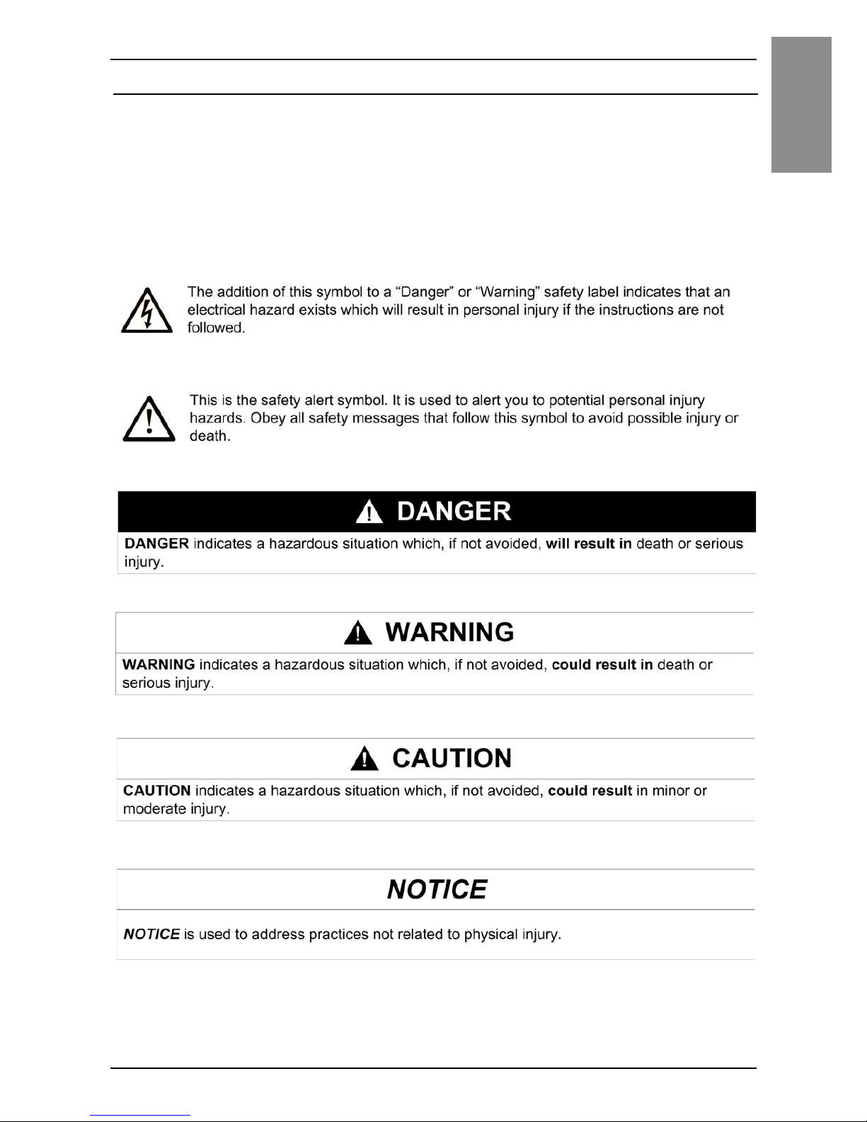
Important Information
Notice
Read these instructions carefully, and look at the equipment to become
familiar with the device before trying to install, operate, or maintain it. The
following special messages may appear throughout this documentation or on
the equipment to warn of potential hazards or to call attention to information
that clarifies or simplifies a procedure.
Page 5

6
English
Safety Information
PLEASE NOTE
Electrical equipment should be installed, operated, serviced, and maintained
only by qualified personnel. No responsibility is assumed by Pro-face for any
consequences arising out of the use of this material.
A qualified person is one who has skills and knowledge related to the
construction and operation of electrical equipment and its installation, and has
received safety training to recognize and avoid the hazards involved.
If the equipment is used in a manner not specified by the manufacturer, the
protection provided by the equipment may be impaired.
Page 6
7
English
Model Numbers
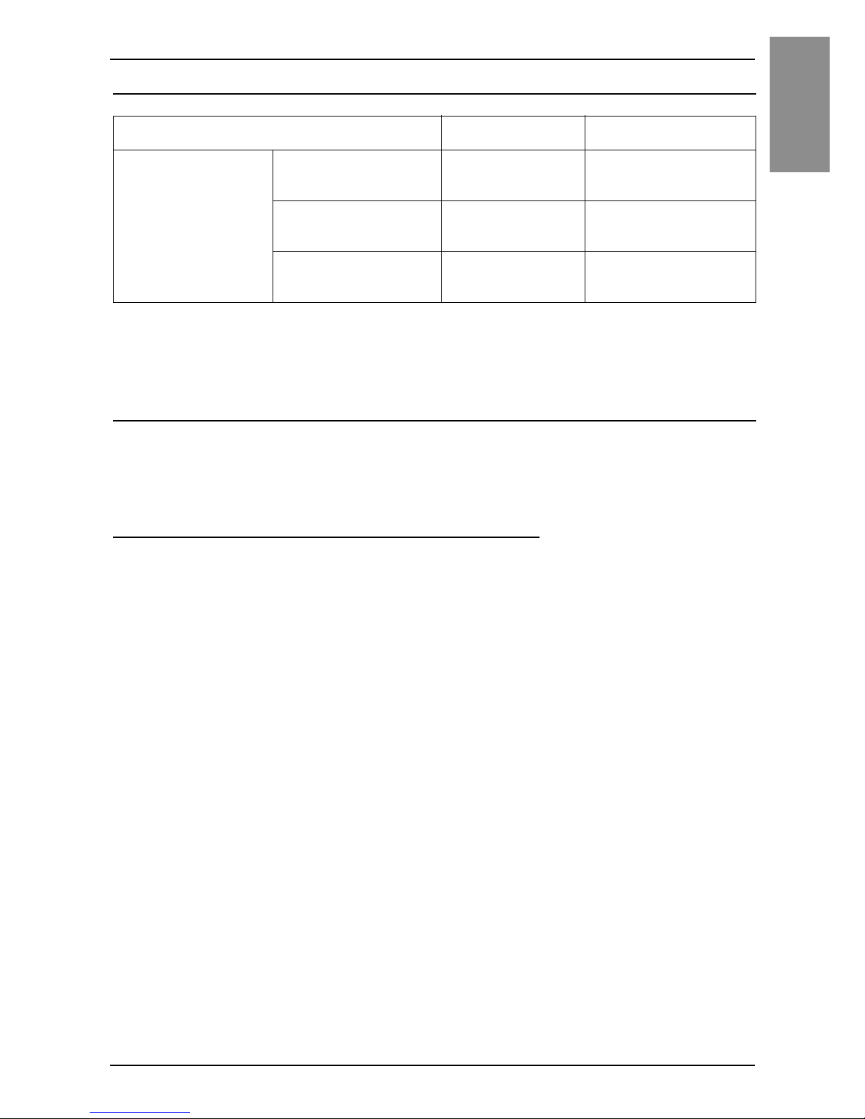
Model Numbers
*1 Includes models with additional alphanumeric characters at the end of the
model number.
Global Code
A global code is assigned to every Pro-face product as a universal model
number.
For more information on product models and their matching global codes,
please refer to the following URL.
http://www.pro-face.com/trans/en/manual/1003.html
Series Model name
Model number
*1
GP-4100 Series
Color Model
Ethernet type GP-4114T
PFXGP4114T1D
PFXGP4114T2D
RS-232C type GP-4115T
PFXGP4115T1D
PFXGP4115T2D
RS-422/485 type GP-4116T
PFXGP4116T1D
PFXGP4116T2D
Page 7
8
English
Overview
Package Contents
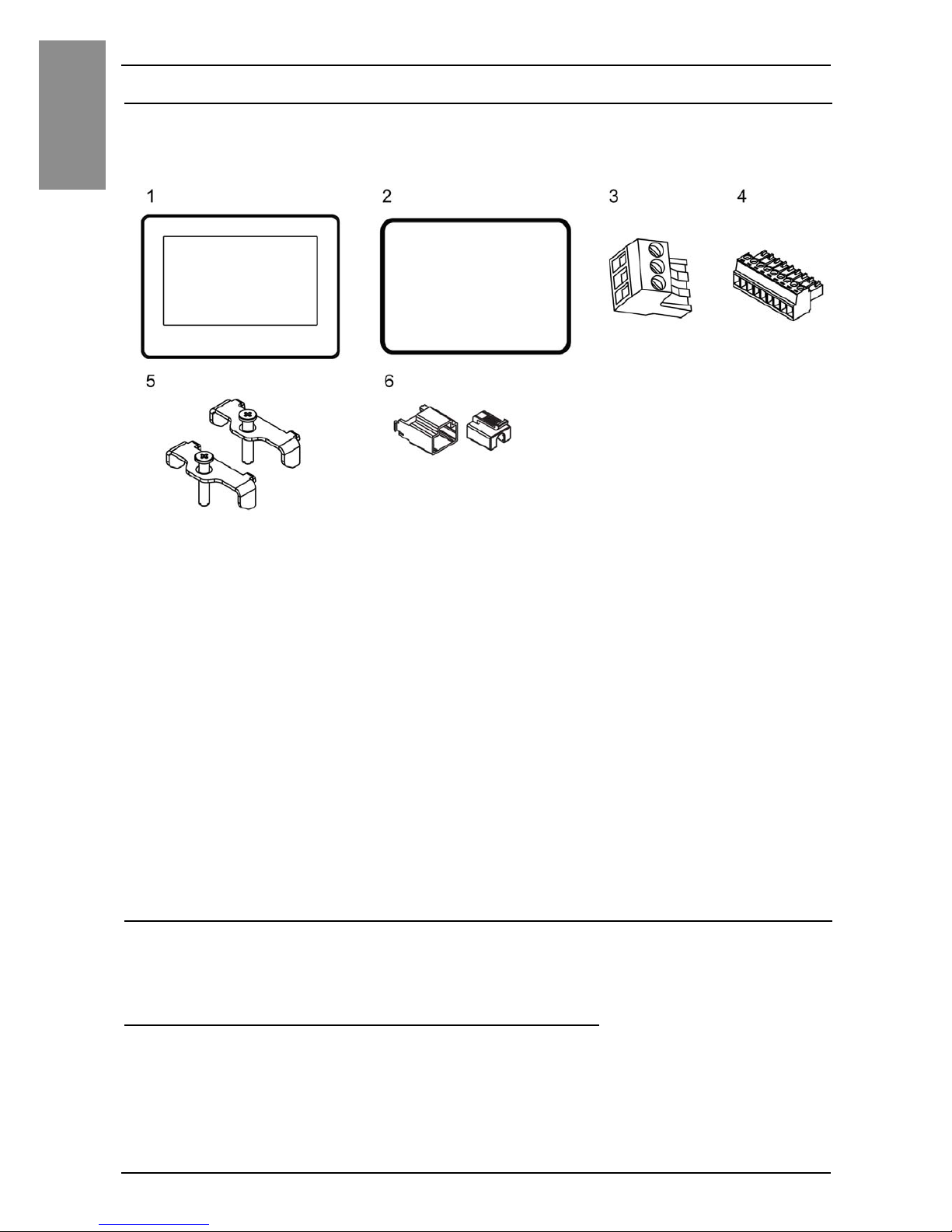
The following items are included in the package. Before using this product,
please confirm that all items listed here are present.
1 GP-4100 Series Color Model: 1
2 Installation Gasket: 1 (attached to this product)
3 DC Power Supply Connector: 1 (attached to this product)
4 COM I/F Connector: 1 (for RS-232C and RS-422/485 types)
5 Installation Fastener: 2 pieces/set
6 USB Clamp Type A (1 port): 1
7 GP-4100 Series Color Model Installation Guide (this guide): 1
8 Warning/Caution Information: 1
This product has been carefully packed, with special attention to quality.
However, should you find anything damaged or missing, please contact your
local distributor immediately.
About the Manual
This manual describes wiring and installation procedures. For more detailed
information, refer to the GP-4100 Series Color Model Hardware Manual.
You can download the manual from our website at
http://www.pro-face.com/trans/en/manual/1001.html.
Page 8
9
English
Part Numbers and Functions
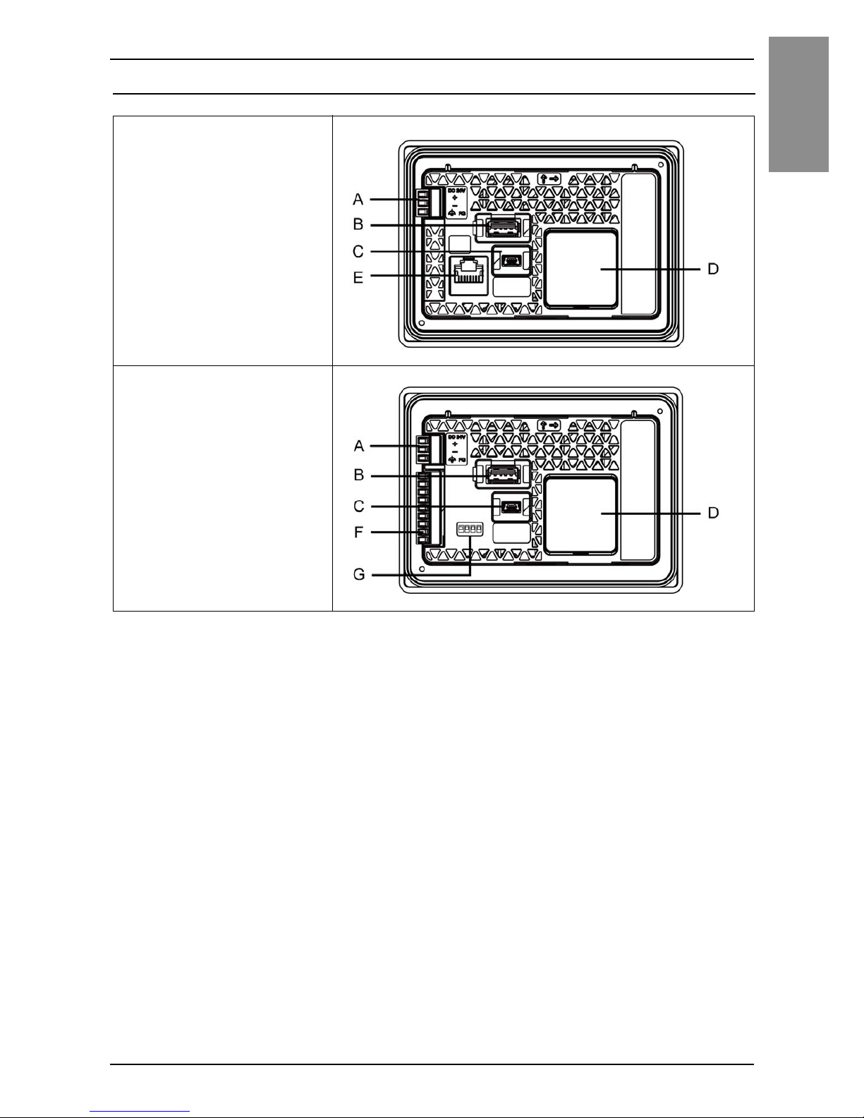
Part Numbers and Functions
A: Power Connector
B: USB (Type A) Interface
C: USB (mini-B) Interface
D: RTC Battery Set Cover
E: Ethernet Interface
F: Serial Interface
G: DIP Switch (see page 12)
Only on RS-422/485 type.
Ethernet type
(Rear view)
RS-232C type, RS-422/
485 type
(Rear view)
Page 9
10
English
Specifications
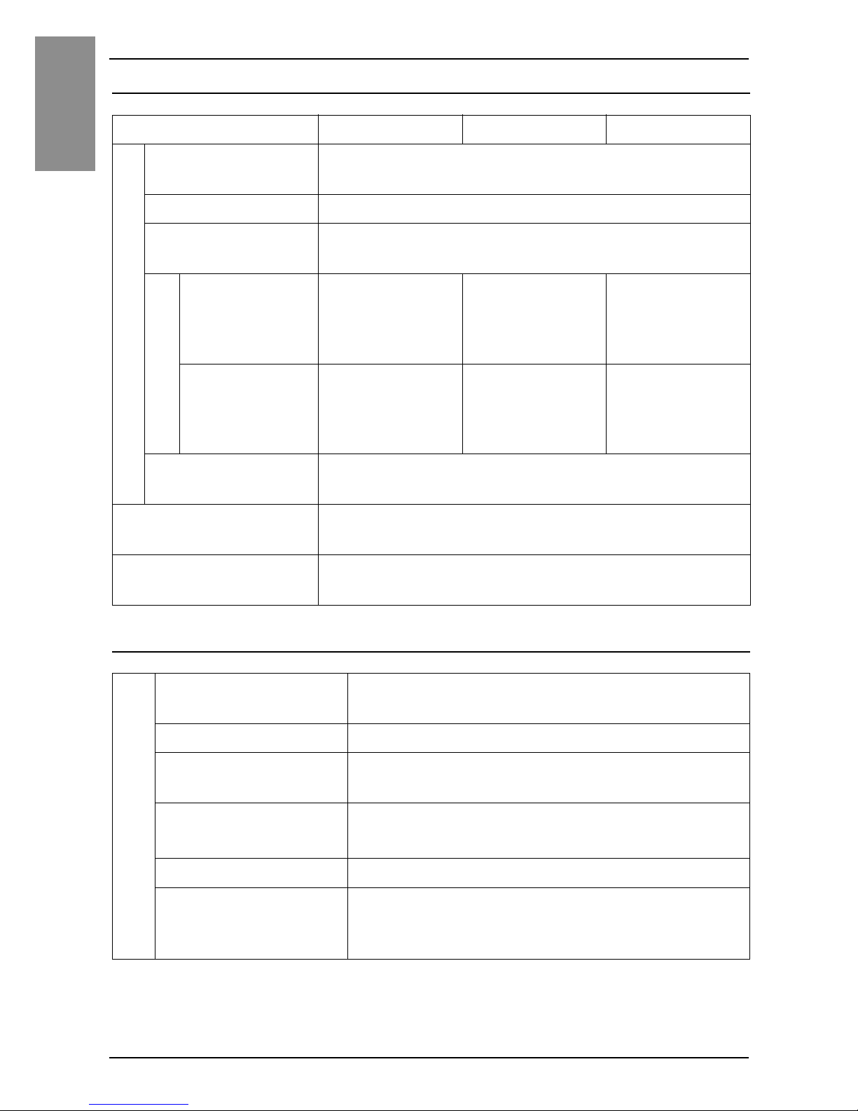
Electrical Specifications
Environmental Specifications
*1 The designated range for the surrounding air temperature is 0 to 45 °C (32
to 113 °F) when the output current of USB (Type A) Interface is from 0.25 A
to 0.5 A.
GP-4114T GP-4115T GP-4116T
Power Supply
Rated input
voltage
12...24 Vdc
Input voltage limits 10.2...28.8 Vdc
Voltage drop
12 Vdc: 1 ms or less
24 Vdc: 3 ms or less
Power consumption
When power is
not supplied to
USB devices
3.9 W or less 3.4 W or less 3.6 W or less
When power is
supplied to
USB devices
8.1 W or less 7.5 W or less 7.7 W or less
In-rush current
12 Vdc: 20 A or less
24 Vdc: 40 A or less
Voltage endurance
1,000 Vac, 20 mA for 1 minute
(between charging and FG terminals)
Insulation resistance
500 Vdc, 10 MΩ or more
(between charging and FG terminals)
Physical environment
Surrounding air
temperature
0...50 °C (32...122 °F)
*1
Storage temperature -20...60 °C (-4...140 °F)
Surrounding air and
storage humidity
10...90% RH (non-condensing, wet bulb
temperature 39 °C [102.2 °F] or less)
Dust
0.1 mg/m
3
(10-7oz/ft3) or less (non-conductive
levels)
Pollution degree For use in Pollution Degree 2 environment
Atmospheric
pressure
(operating altitude)
800...1,114 hPa (2,000 m [6,561 ft] or lower)
Page 10
11
English
Interface
Interface Caution
Use only the SELV (Safety Extra-Low Voltage) circuit to connect the COM,
USB, and LAN interfaces.
Serial Interface
For information on how to connect controllers and other types of equipment,
refer to the corresponding device driver manual of your screen editing
software.
The serial interface is not isolated. The SG (signal ground) and the FG
(functional ground) terminals are connected inside this product.
NOTE : Use within the rated current.
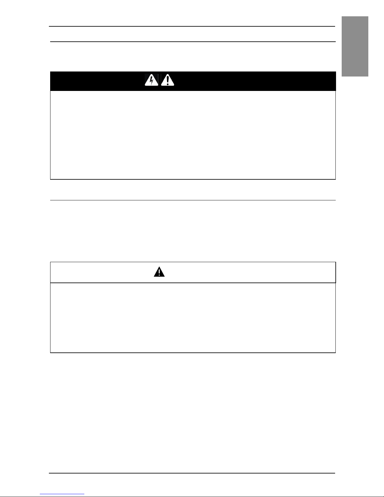
DANGER
ELECTRIC SHOCK AND FIRE
When using the SG terminal to connect an external device to this product:
• Verify that a short-circuit loop is not created when you set up the system.
• Connect the SG terminal to remote equipment when the external device is
not isolated.
• Connect the SG terminal to a known reliable ground connection to reduce
the risk of damaging the circuit.
Failure to follow these instructions will result in death or serious injury.
CAUTION
LOSS OF COMMUNICATION
• All connections to the communication ports must not put excessive stress
on the ports.
• Securely attach communication cables to the panel wall or cabinet.
Failure to follow these instructions can result in injury or equipment
damage.
Page 11
12
English
Interface
RS-232C and RS-422/485
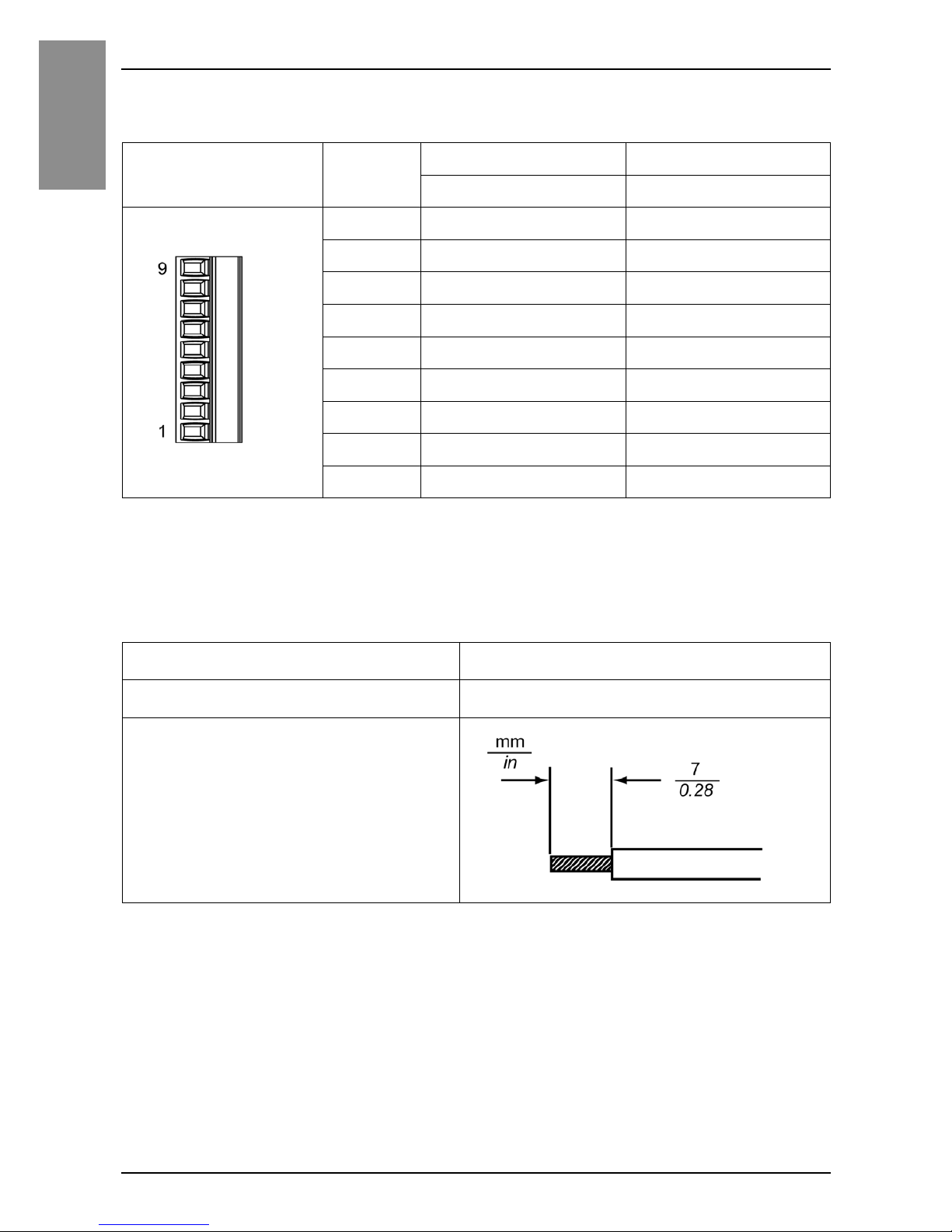
COM I/F Connector (9-pin, 2-piece terminal block)
NOTE : You can set a termination resistor using the DIP Switch (4-bit) on the rear of the
RS-422/485 type. Factory default settings are “OFF” (no termination resistor).
Check the termination resistor requirement for connection to the connected device
(PLC) and set up if necessary.
Communication Cable Specifications
*1 When inserting two wires into one terminal connector, the simple wire
diameter is 0.08 to 0.5 mm
2
(AWG 28 to 22), and the stranded wire
diameter is 0.08 to 0.75 mm
2
(AWG 28 to 20).
*2 If the conductor's stranded wires are not twisted correctly, the ends of the
wires may either short against each other, or against an electrode.
Cable connection
side
Pin No. RS-232C RS-422/485
Signal name Signal name
1CI(RI) CSB
2CD CSA
3 CS(CTS) ERB
4 RS(RTS) ERA
5SG SG
6 DR(DSR) RDB
7 ER(DTR) RDA
8 RD(RXD) SDB
9SD(TXD) SDA
Communication cable diameter
*1
0.14...1.5 mm2 (AWG 28...16)
Conductor type
Simple or stranded wire
*2
Conductor length
Page 12
13
Interface
English
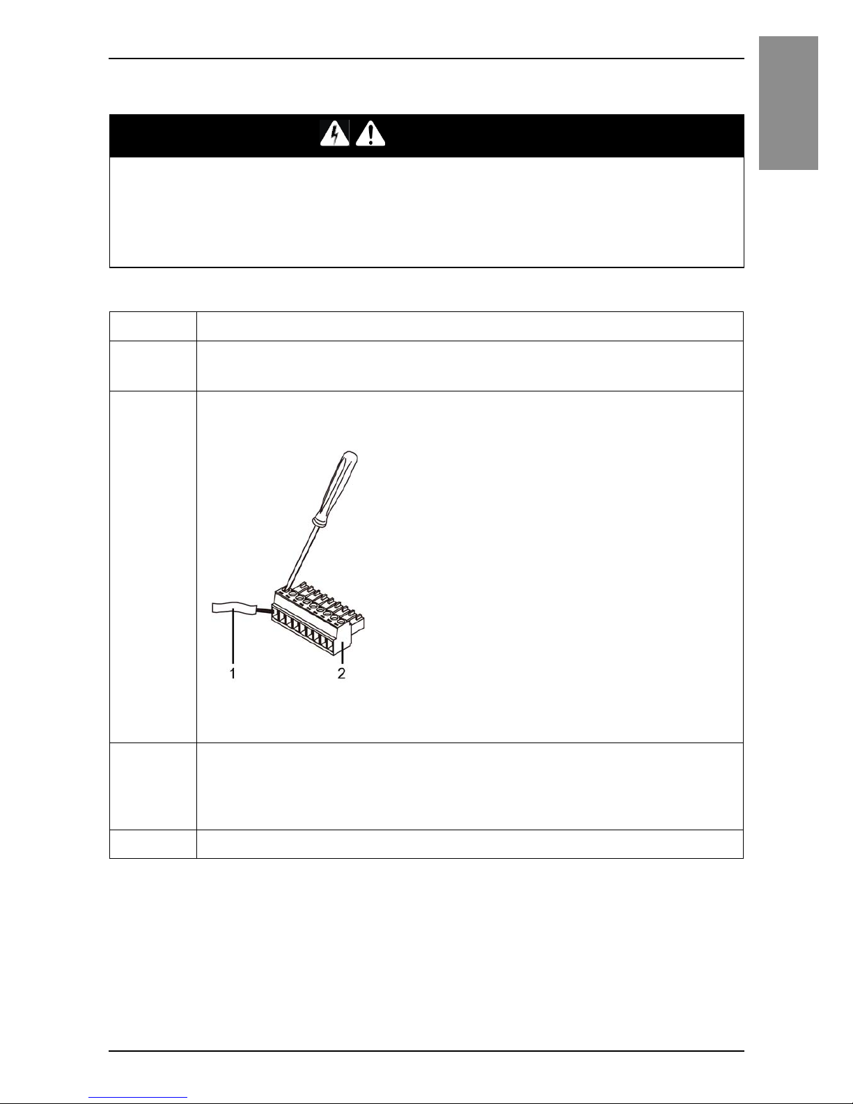
Wiring the COM Interface Connector
DANGER
ELECTRIC SHOCK
Always disconnect the connector from this product before wiring the
connector.
Failure to follow these instructions will result in death or serious injury.
Step Action
1 Use a flat-blade screwdriver (Size 0.4 X 2.5) to loosen the
terminal screws.
2 Strip the communications cable, and attach it to the terminal
connector.
1 Communication cable
2 COM I/F Connector
3 Use a flat-blade screwdriver to tighten the terminal screws on the
terminal connector from step 2.
NOTE : The torque required to tighten these screws is 0.196 N•m (1.735 lbin).
4 Insert the connector to this product’s serial interface.
Page 13

14
English
Interface
NOTICE
BROKEN ENCLOSURE
Do not exert more than 0.196 N•m (1.735 lb-in) of torque when tightening
the screws.
Failure to follow these instructions can result in equipment damage.
Page 14
15
English
Installation
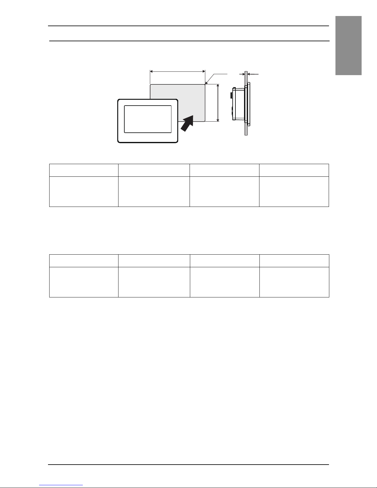
Panel Cutout Dimensions
Based on the panel cutout dimensions, open a mount hole on the panel.
Panel cutout dimensions for color model
When installing to panel cutout for monochrome model (GP-410*)
NOTE : The panel cutout adapter (model number: PFXZCFAD31) is required for this type
of installation.
WH X R
112.5 mm
(4.43 in)
77.5 mm
(3.05 in)
1.5...6 mm
(0.06...0.24 in)
2...3 mm
(0.08...0.12 in)
WH X R
105 mm
(4.13 in)
66 mm
(2.6 in)
1.5...6 mm
(0.06...0.24 in)
2...3 mm
(0.08...0.12 in)
X
W
R
H
+1-0+0.04
-0+1-0
+0.04
-0
+1
-0
+0.04
-0+1-0
+0.04
-0
Page 15
16
English
Installation
Installation Requirements
This product is designed for use on flat surfaces of Type 1, Type 4X (Indoor
Use Only), Type 13 Enclosure or IP65F.
Be aware of the following when building this product into an end-use product:
• The rear face of this product is not approved as an enclosure. When building this
product into an end-use product, be sure to use an enclosure that satisfies
standards as the end-use product’s overall enclosure.
• Install this product in an enclosure with mechanical rigidity.
• This product is not designed for outdoor use. UL certification obtained is for
indoor use only.
• Install and operate this product with its front panel facing outward.
NOTE :
• IP65F is not part of the UL certification.
• The necessary torque to fasten the screw of the enclosed installation fasteners is
0.35 N•m (3.1 lb-in).
Check that the installation wall or cabinet surface is flat, in good condition
and has no jagged edges. Metal reinforcing strips may be attached to the
inside of the wall, near the panel cutout, to increase its rigidity.
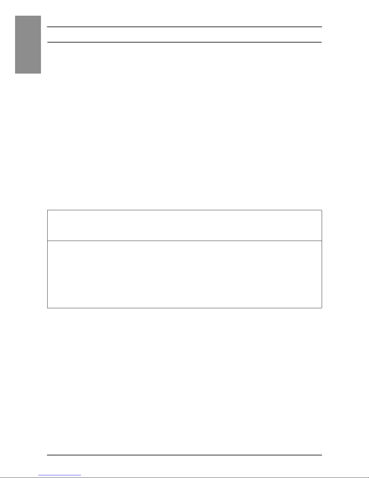
Decide on the thickness of the enclosure wall, based on the level of strength
required: 1.5...6 mm (0.06...0.24 in).
Even if the installation wall thickness is within the recommended range for
the panel cutout dimensions, depending on wall’s material, size, and
installation location of this product and other devices, the installation wall
could warp. To prevent warping, the installation surface may need to be
strengthened.
Page 16
17
Installation
English
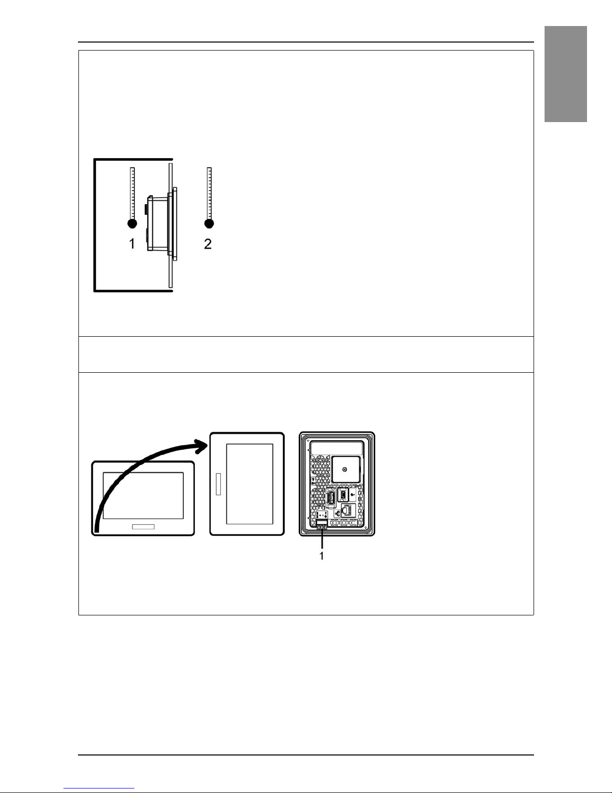
Be sure that the surrounding air temperature and the ambient humidity are
within their designated ranges. Surrounding air temperature: 0 to 50 °C (32
to 122 °F); ambient humidity: 10 to 90% RH; wet bulb temperature:
maximum 39 °C (102 °F) (see page 10). When installing this product in a
cabinet or enclosure, the surrounding air temperature is the cabinet’s or
enclosure’s internal temperature.
1 Cabinet interior
2 Panel face
Be sure that heat from surrounding equipment does not cause this product
to exceed its standard operating temperature.
When mounting this product vertically, ensure that the left side of this
product faces up. In other words, the DC power connector should be at the
bottom.
1 Power connector
NOTE : For a vertical mounting, make sure your screen editing software supports the
function.
Page 17
18
English
Installation
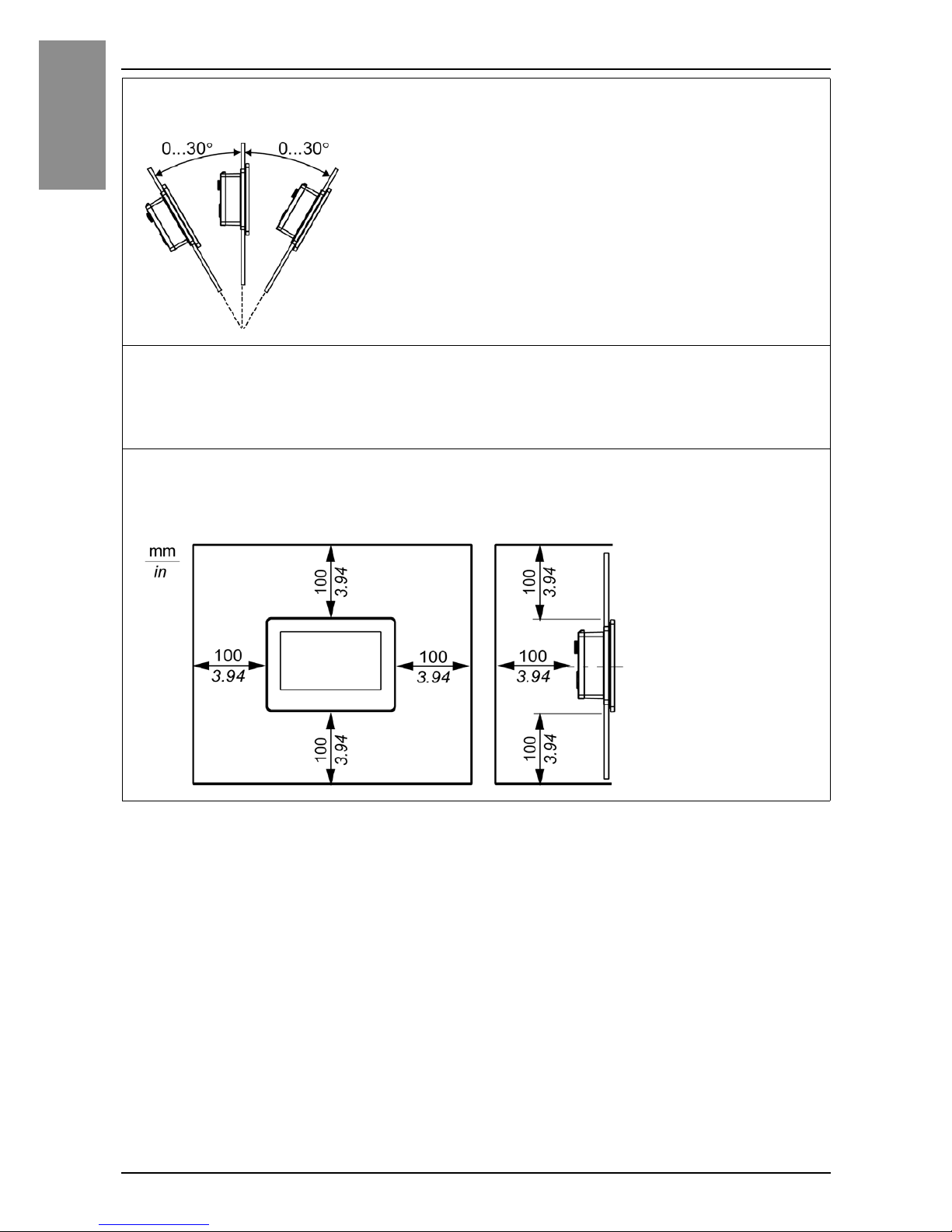
When installing this product in a slanted position, the product face should
not incline more than 30°.
When installing this product in a slanted position with an incline more than
30°, the ambient temperature must not exceed 40 °C (104 °F). You may
need to use forced air cooling (fan, A/C) to ensure the ambient operating
temperature is 40 °C or less (104 °F or less).
For easier maintenance, operation and improved ventilation, install this
product at least 100 mm (3.94 in) away from adjacent structures and other
equipment as shown in the following illustration:
Page 18
19
Installation
English
Installation Procedure
DANGER
HAZARD OF ELECTRIC SHOCK, EXPLOSION OR ARC FLASH
• Remove all power from the device before removing any covers or elements
of the system, and prior to installing or removing any accessories,
hardware, or cables.
• Unplug the power cable from both this product and the power supply.
• Always use a properly rated voltage sensing device to confirm power is off.
• Replace and secure all covers or elements of the system before applying
power to this product.
Failure to follow these instructions will result in death or serious injury.
NOTICE
EQUIPMENT DAMAGE
Keep this product stabilized in the panel cutout while you are installing or
removing the screw fasteners.
Failure to follow these instructions can result in equipment damage.
Page 19
20
English
Installation
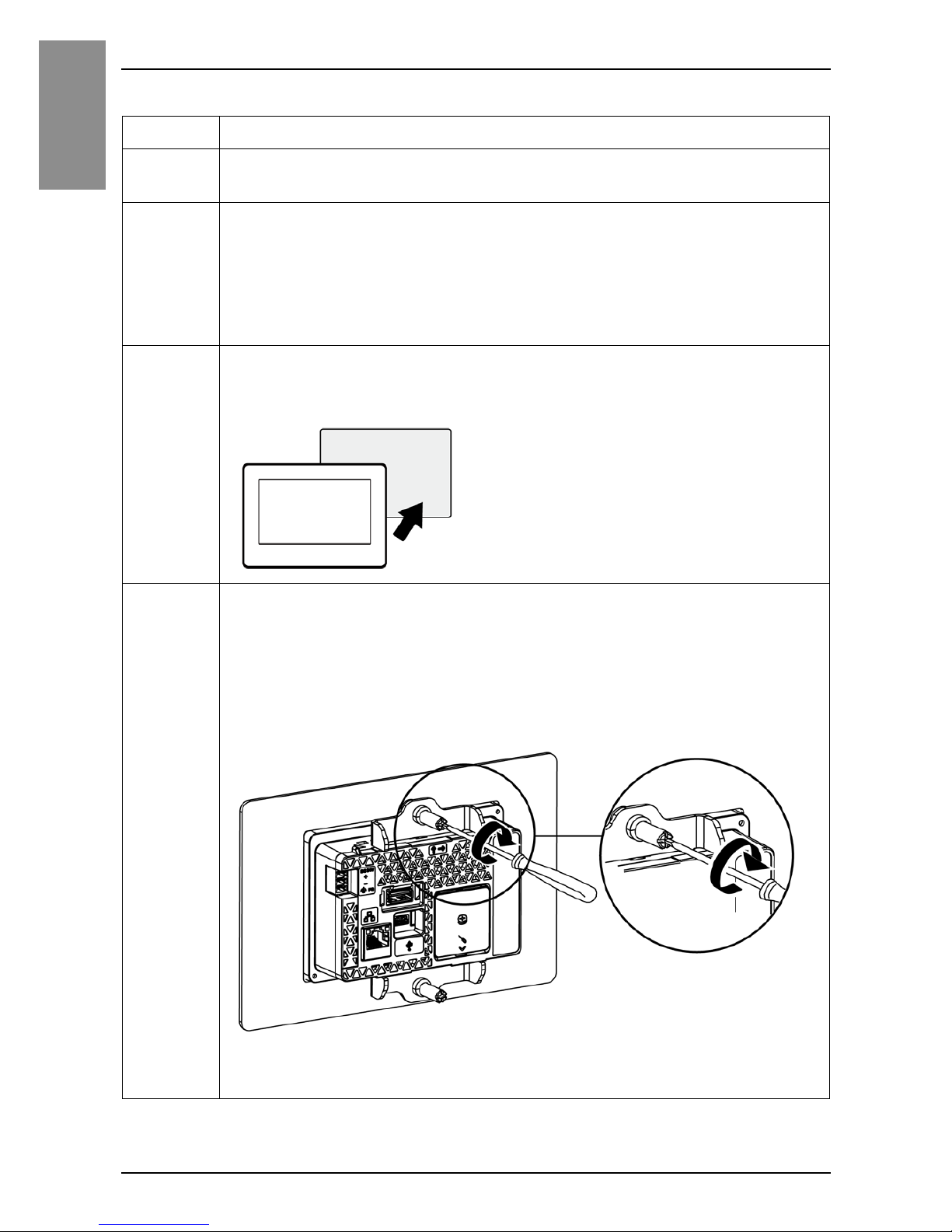
Installing to panel cutout for Color Model
Step Action
1 Place this product on a clean and level surface with the screen
facing down.
2 Check that this product’s gasket is seated securely into the
bezel’s groove, which runs around the perimeter of the display
panel frame.
NOTE : Always use the installation gasket, since it absorbs vibration in
addition to repelling water. For the procedure on replacing the installation
gasket, refer to the GP-4100 Series Color Model Hardware Manual.
3 Based on this product’s panel cutout dimensions (see page 15),
open a mount hole on the panel and attach this product to the
panel from the front side.
4 Insert the installation fastener hooks into the insertion slots on
this product.
In a clockwise direction, tighten the installation fastener's screws
with a screwdriver.
There are two insertion slots on both the top and bottom of this
product.
The necessary torque is 0.35 N•m (3.1 lb-in)
NOTE : If you exceed the recommended torque when tightening the
installation fastener’s screws, the front of this product may become distorted.
Page 20
21
Installation
English
NOTICE
BROKEN ENCLOSURE
Do not exert more than 0.35 N•m (3.1 lb-in) of torque when tightening the
fastener’s screws.
Failure to follow these instructions can result in equipment damage.
CAUTION
RISK OF INJURY
Do not drop this product when you remove it from the panel.
• Hold this product in place after removing the fasteners.
• Use both hands.
Failure to follow these instructions can result in injury or equipment
damage.
Page 21
22
English
Installation
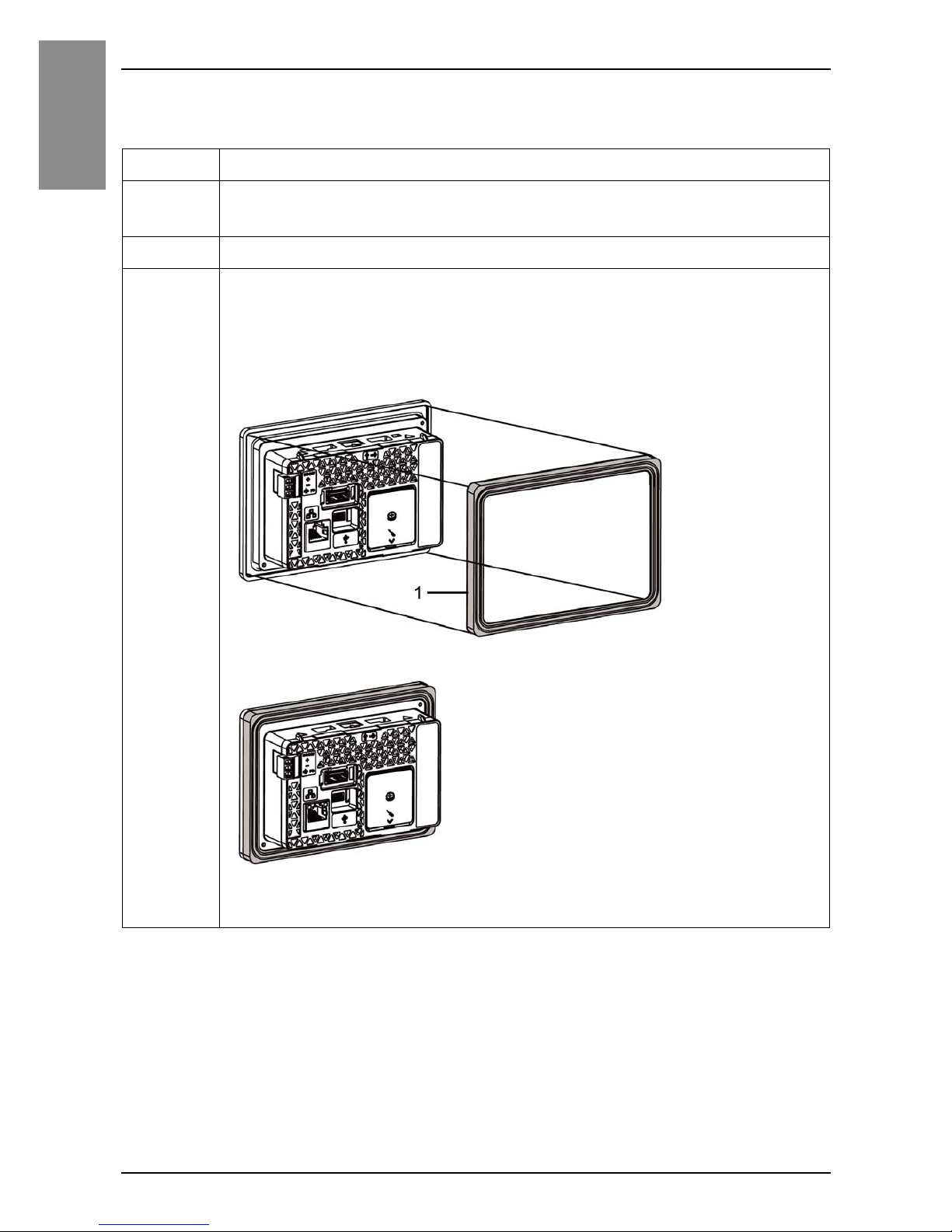
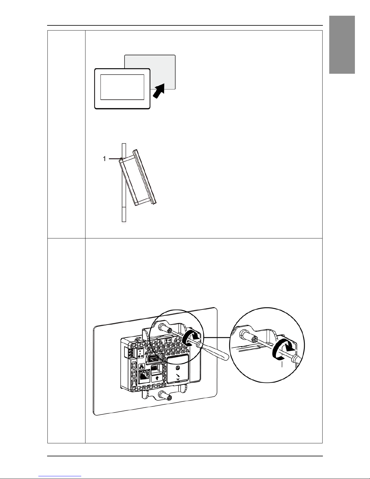
Installing to panel cutout for Monochrome Model
(GP-410*)
Step Action
1 Place this product on a clean and level surface with the screen
facing down.
2 Remove the gasket from this product.
3 Attach the panel cutout adapter (model number: PFXZCFAD31)
to this product.
Check that the panel cutout adapter is seated securely into the
bezel’s groove, which runs around the perimeter of the display
panel frame.
1 Panel cutout adapter
NOTE : Always use the panel cutout adapter, since it absorbs vibration in
addition to repelling water.
Page 22
23
Installation
English
4 From the front of the panel, attach this product to the mount hole
for the monochrome model (see page 15).
NOTE : This product has two projections on the top to prevent falling during
installation. Please insert this product into the panel at an angle to avoid
hitting the projections.
1 Projections
5 Insert the installation fastener hooks into the insertion slots on
this product.
In a clockwise direction, tighten the installation fastener's screws
with a screwdriver.
There are two insertion slots on both the top and bottom of this
product.
The necessary torque is 0.35 N•m (3.1 lb-in).
NOTE : If you exceed the recommended torque when tightening the
installation fastener’s screws, the front of this product may become distorted.
Page 23

24
English
Installation
NOTICE
BROKEN ENCLOSURE
Do not exert more than 0.35 N•m (3.1 lb-in) of torque when tightening the
fastener’s screws.
Failure to follow these instructions can result in equipment damage.
Page 24
25
English
Wiring
Wiring
NOTE :
• The SG (signal ground) and FG (functional ground) terminals are connected internally in
this product.
• When the FG terminal is connected, be sure the wire is grounded. Not grounding this
product can result in excessive electromagnetic interference (EMI).
DANGER
HAZARD OF ELECTRIC SHOCK, EXPLOSION OR ARC FLASH
• Remove all power from the device before removing any covers or elements
of the system, and prior to installing or removing any accessories,
hardware, or cables.
• Remove power before wiring this product’s power terminals.
• Always use a properly rated voltage sensing device to confirm power is off.
• Replace and secure all covers or elements of the system before applying
power to this product.
• Use only the specified voltage when operating this product. This product is
designed to use 12 to 24 Vdc. Always check whether your device is DC
powered before applying power.
• Since this product is not equipped with a power switch, be sure to connect
a power switch to the power supply.
• Be sure to ground this product’s FG terminal.
Failure to follow these instructions will result in death or serious injury.
Page 25
26
English
Wiring
DC Power Cord Preparation
• Make sure the ground wire is either the same or heavier gauge than the
power wires.
• Do not use aluminum wires in the power supply’s power cord.
• If the ends of the individual wires are not twisted correctly, the wires may
create a short circuit.
• The conductor type is solid or stranded wire.
• Use copper wire rated for 75 °C (167°F).
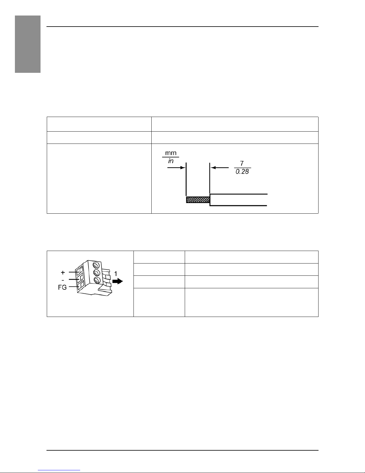
Power Connector Specifications
Power cord diameter
0.75...1.5 mm
2
(AWG 18...16)
Conductor type Solid or stranded wire
Conductor length
1 Insertion direction
Connection Wire
+ 12...24 Vdc
–0Vdc
FG Grounded terminal connected to the
panel chassis.
Page 26
27
Wiring
English
How to Connect the DC Power Cord
Wiring Precautions
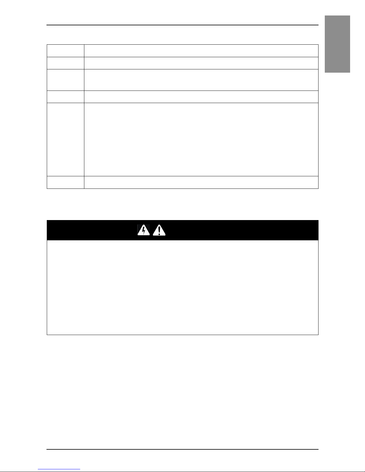
Step Action
1 Confirm the power cord is not connected to the power supply.
2 Check the rated voltage, and remove the “DC24V” sticker on the
DC power supply connector.
3 Remove the power connector (plug) from this product.
4 Strip the membrane of the power cord, and connect them to the
Power Connector.
NOTE :
• Use a flat-blade screwdriver (Size 0.4 x 2.5) to tighten the terminal screws.
The torque require to tighten these screws is 0.22 to 0.25 N•m (1.95 to 2.2
lb-in).
• Do not solder the cable connection. Doing so may either damage this
product due to abnormal heat or cause a fire.
5 Reattach the power connector (plug).
DANGER
SHORT CIRCUIT, FIRE, OR UNINTENDED EQUIPMENT
OPERATION
Avoid excessive force on the power cable to prevent accidental
disconnection
• Securely attach power cables to an installation panel or cabinet.
• Use the necessary torque to tighten this product terminal block screws.
• Install and fasten this product on installation panel or cabinet prior to
connecting power supply and communication lines.
Failure to follow these instructions will result in death or serious injury.
Page 27
28
English
Wiring
Improving Noise/Surge Resistance
• This product’s power supply cord should not be bundled with or kept close to
main circuit lines (high voltage, high current), power lines, or input/output
lines, and their various systems should be kept separate. When power lines
cannot be wired via a separate system, use shielded cables for input/output
lines.
• Make the power cord as short as possible, and be sure to twist the ends of
the wires together (i.e. twisted pair cabling) from close to the power supply
unit.
• If there is an excess amount of noise on the power supply line, connect a
noise reducing transistor before turning on the power.
• Connect a surge protection device to handle power surges.
• To increase noise resistance, attach a ferrite core to the power cable.
Power Supply Connections
• Use SELV (Safety Extra-Low Voltage) circuit and LIM (Limited Energy) circuit
for DC input.
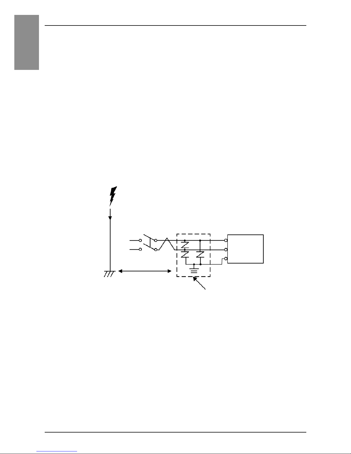
• The following shows a surge protection device connection.
Attach a surge protection device to prevent damage to this product as a result
of a lightning-induced power surge from a large electromagnetic field
generated from a direct lightning strike. We also strongly recommend to
connect the crossover grounding wire of this product to a position close to the
ground terminal of the surge protection device.
It is expected that there will be an effect on this product due to fluctuations in
grounding potential when there is a large surge flow of electrical energy to
the lightning rod ground at the time of a lightning strike. Provide adequate
distance between the lightning rod grounding point and the surge protection
device grounding point.
Surge protection device
FG
This product
Lightning
Lightning rod
Ground
Provide adequate
distance.
Page 28
29
Wiring
English
Grounding
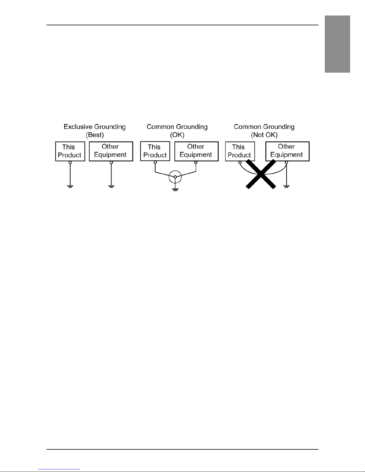
• Check that the grounding resistance is 100 Ω or less.
*1
• The FG wire should have a cross sectional area greater than 2 mm2 (AWG
14)
*1
. Create the connection point as close to this product as possible, and
make the wire as short as possible. When using a long grounding wire,
replace the thin wire with a thicker wire, and place it in a duct.
*1 Observe local codes and standards.
Short Circuit Prevention
• The SG (signal ground) and FG (functional ground) terminals are connected
internally in this product. When connecting the SG line to another device, be
sure that no shorting loops are formed.
Page 29
30
English
Connecting to the USB Interface
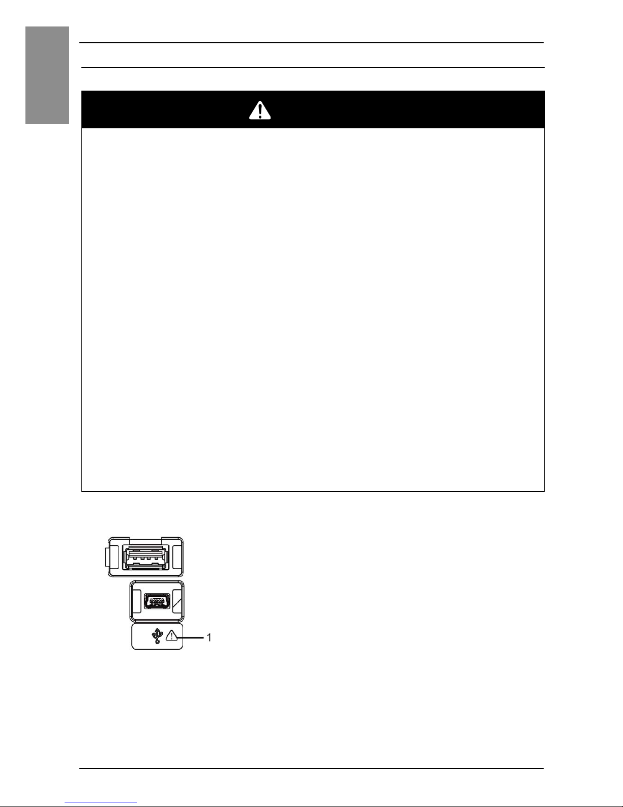
Connecting to the USB Interface
USB Interface
1 Safety alert symbol (see the safety messages above)
DANGER
POTENTIAL FOR EXPLOSION
• Verify that the power, input and output (I/O) wiring are in accordance with
Class I, Division 2 wiring methods.
• Substitution of any component may impair suitability for Class I, Division 2.
• Do not disconnect equipment while the circuit is live or unless the area is
known to be free of ignitable concentrations.
• Remove power before attaching or detaching any connectors to or from this
product.
• Ensure that power, communication, and accessory connections do not place
excessive stress on the ports. Consider the vibration in the environment when
making this determination.
• Securely attach power, communication, and external accessory cables to the
panel or cabinet.
• Use only commercially available USB cables.
• Use only non-incendive USB configurations.
• Suitable for use in Class I, Division 2, Groups A, B, C, D Hazardous Locations.
• Confirm that the USB cable has been attached with the USB clamp before
using the USB interface.
• Use the USB (mini-B) interface for temporary connection only during
maintenance and setup of the device.
• Do not use the USB (mini-B) interface in hazardous locations.
Failure to follow these instructions will result in death or serious injury.
Page 30
31
Connecting to the USB Interface
English
USB Clamp
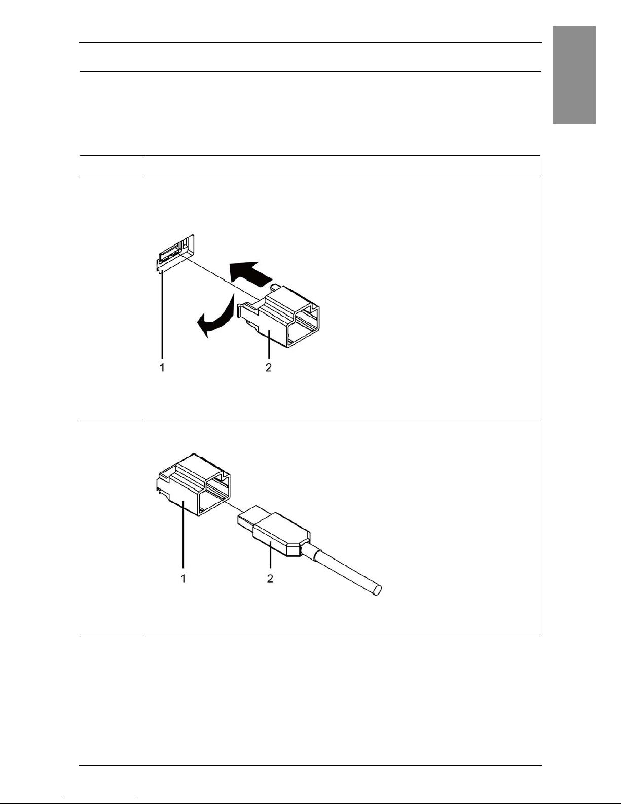
When using a USB device, attach a USB clamp to the USB interface to
prevent the USB cable from being disconnected.
Attaching the USB Holder
Step Action
1 Attach the USB holder to the USB (Type A) Interface on this
product. Hook the clip on the right-side of the USB holder into the
slot beside the interface, then insert the left clip to attach.
1 USB (Type A) interface
2 USB holder
2 Insert the USB cable into the USB (Type A) interface.
1 USB holder
2USB cable
Page 31
32
English
Connecting to the USB Interface
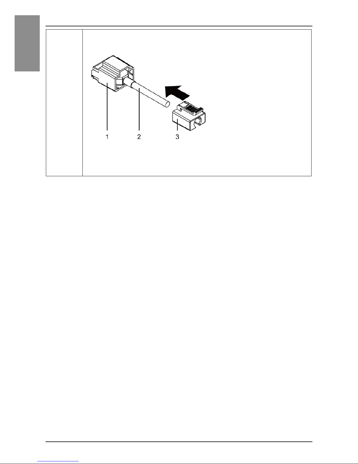
3 Attach the USB cover to fix the USB cable in place. Insert the
USB cover into the USB holder.
1 USB holder
2USB cable
3 USB cover
Page 32
33
Connecting to the USB Interface
English
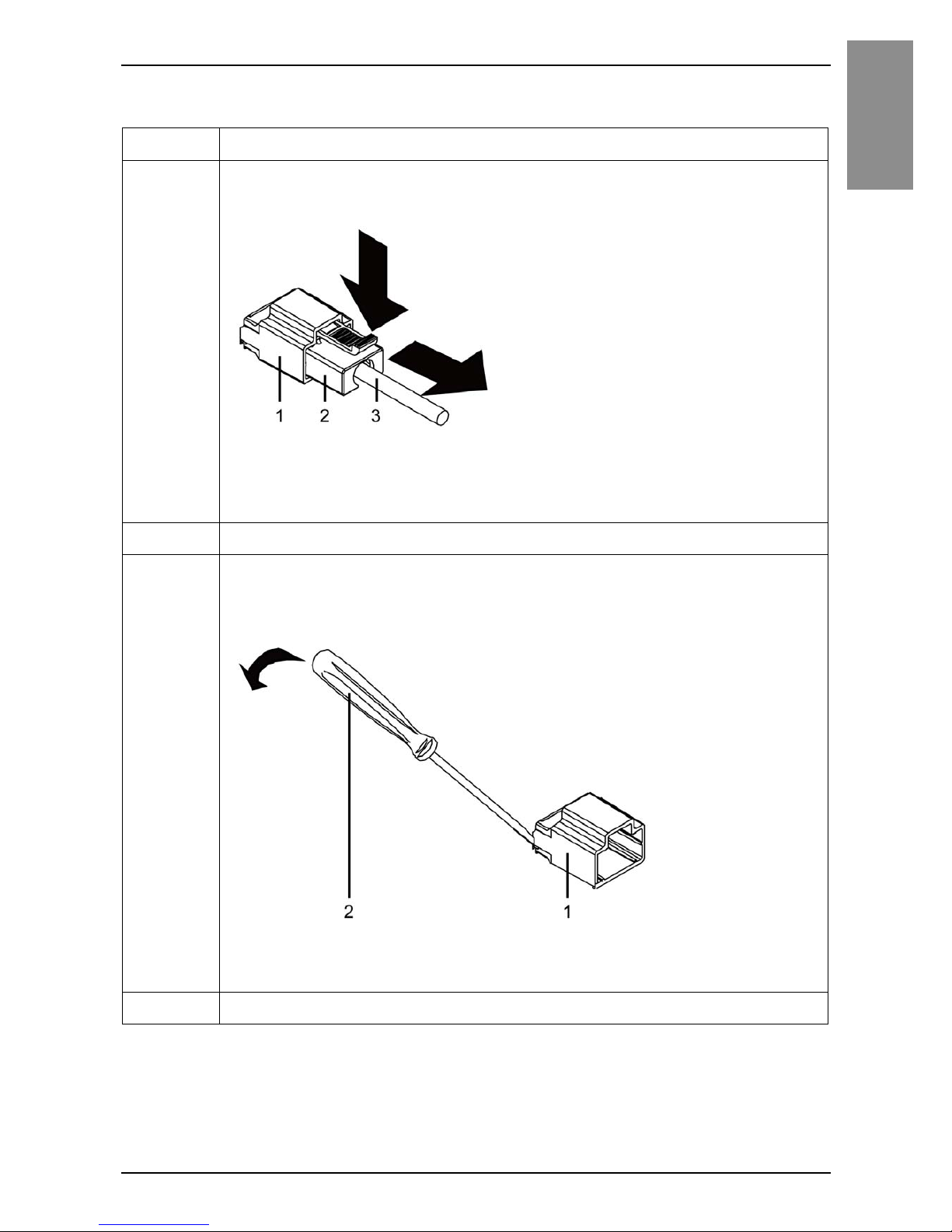
Removing the USB Holder
Step Action
1 Push down the tab of the USB cover and then remove the USB
cover.
1 USB holder
2 USB cover
3USB cable
2 Remove the USB cable from the USB (Type A) interface.
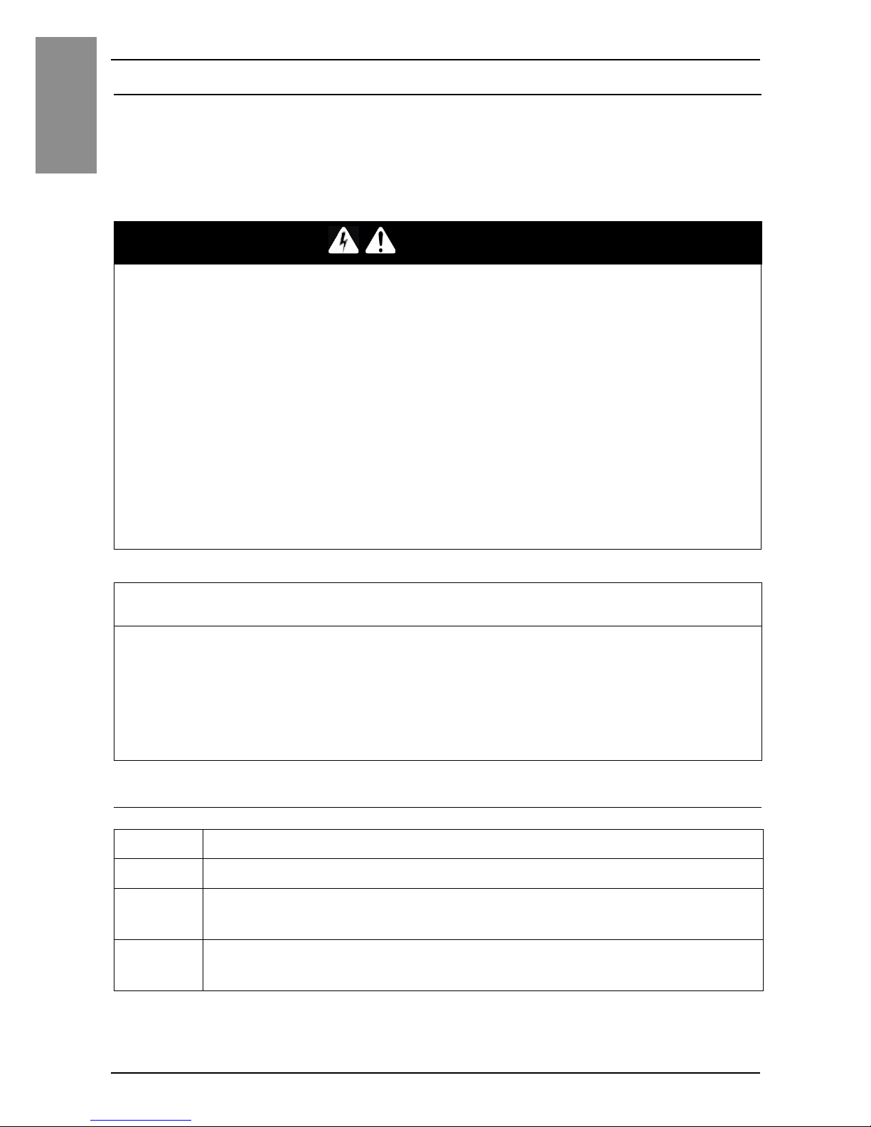
3 As shown in the following illustration, insert a screwdriver
between this product and the USB holder to pry out the USB
holder.
1 USB holder
2 Flat-blade screwdriver less than 6 mm (0.23 in)
4 Remove the holder.
Page 33
34
English
RTC Battery Set
Overview
RTC Battery Set (model number: PFXZGPRTC1) provides system date and
time information and supports related functions requiring a real-time clock. To
keep time continuity when power is off, use a non-rechargeable but
replaceable battery provided with the RTC Battery Set. Replacing the battery
initializes the clock data.
Attaching the RTC Battery Set
DANGER
HAZARD OF ELECTRIC SHOCK, EXPLOSION OR ARC FLASH
• Remove all power from the device before removing any covers or elements
of the system, and prior to installing or removing any accessories,
hardware, or cables.
• Unplug the power cable from both this product and the power supply.
• Always use a properly rated voltage sensing device to confirm power is off.
• Replace and secure all covers or elements of the system before applying
power to this product
• Use only the specified voltage when operating this product. This product is
designed to use 12 to 24 Vdc. Always check whether your device is DC
powered before applying power.
Failure to follow these instructions will result in death or serious injury.
NOTICE
LOSS OF DATA
• Replace the battery regularly every five years after you purchase the RTC
Battery Set.
• Allow only qualified personnel to change the battery.
Failure to follow these instructions can result in equipment damage.
Step Action
1 Disconnect the power supply from this product.
2 Touch the housing or ground connection to discharge any
electrostatic charge from your body.
3 Place this product on a flat, level surface, with the rear side
pointing up.
Page 34
35
RTC Battery Set
English
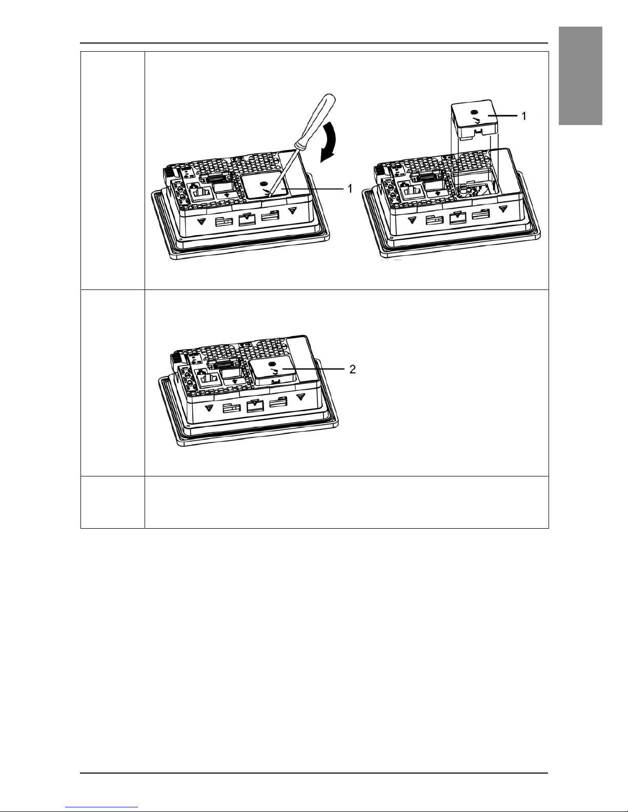
4 Open the RTC Battery Set Cover on this product using the flat-
blade screwdriver:
1 RTC Battery Set Cover
5 Insert the top of the RTC Battery Set first, then press the bottom
until it clicks to affix the RTC Battery Set onto this product.
2 RTC Battery Set
6 Reconnect the power supply to this product.
NOTE : After reconnecting the power supply, set up the clock again. Refer
to your screen editing software manual on how to set up the clock.
Page 35
36
English
RTC Battery Set
Replacing the Battery
Use only the replacement battery (model number: PFXZGEBT1).
DANGER
EXPLOSION, FIRE, OR CHEMICAL HAZARD
Follow these instructions for the lithium batteries:
• Use this product's replacement battery only.
• Protect battery from any potential short circuit.
• Recycle or properly dispose of used batteries.
• Do not recharge, disassemble or heat above 80 °C (176 °F).
• Use your hands or insulated tools to remove or replace the battery.
• Maintain proper polarity when inserting and connecting a new battery.
Failure to follow these instructions will result in death or serious injury.
Step Action
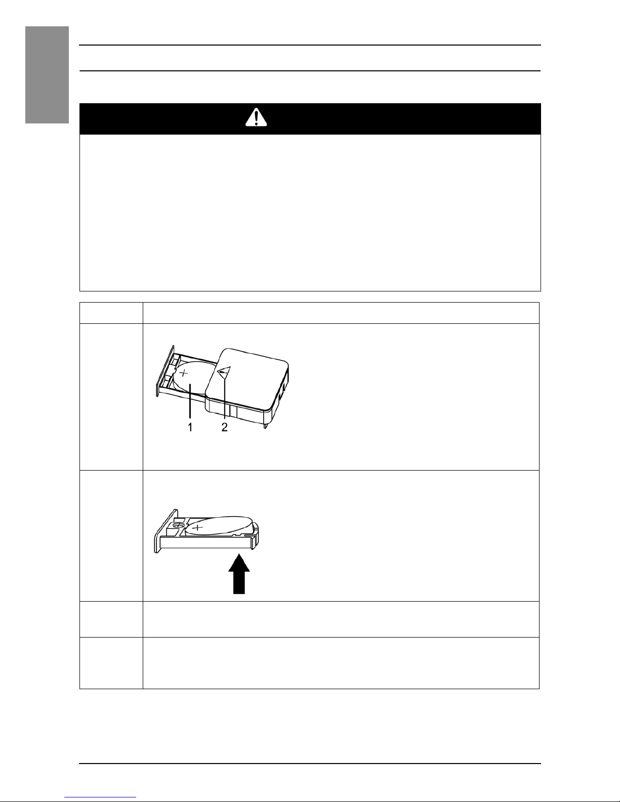
1 Pull out the tray of the RTC Battery Set.
1Battery
2 Safety alert symbol (see the safety messages above)
2 Remove the spent battery from the tray by touching the battery
from the bottom.
3 Put the new battery on the tray in accordance with the polarity
markings in the tray and on the battery.
4 Close the tray.
NOTE : Refer to “Attaching the RTC Battery Set” (see page 34) before you
attach the RTC Battery Set to this product.
Page 36
37
English
Maintenance
Cleaning this product
When this product gets dirty, soak a soft cloth in water with a neutral detergent,
wring the cloth tightly and wipe this product.
NOTICE
EQUIPMENT DAMAGE
• Power off this product before cleaning it.
• Do not use hard or pointed objects to operate the touch panel.
• Do not use paint thinner, organic solvents, or a strong acid compound to clean
the unit.
Failure to follow these instructions can result in equipment damage.
Page 37
38
English
Standards
Standards
For information on certifications and standards, such as certified models and
certificates, see the product markings or the following URL:
http://www.pro-face.com/trans/en/manual/1002.html
DANGER
POTENTIAL FOR EXPLOSION
• Suitable for use in Class I, Division 2, Groups A, B, C, and D Hazardous
Locations.
• Substitution of any component may impair suitability for Class I, Division 2.
• Do not disconnect equipment while the circuit is live or unless the area is
known to be free of ignitable concentrations.
• Always confirm that this product is suitable for use in hazardous locations
by checking that the ANSI/ISA 12.12.01 and CSA C22.2 N°213 certification
appears on the product label.
• Do not attempt to install, operate, modify, maintain, service, or otherwise
alter this product except as permitted in this manual. Unpermitted actions
may impair the suitability of this product for Class I, Division 2 operation.
• To power on or power off this product installed in a Class I, Division 2
hazardous location, you must either:
• Use a switch located outside the hazardous environment, or
• Use a switch certified for Class I, Division 1 operation inside the hazardous
area.
• Do not disconnect equipment unless power has been switched off or the area
is known to be non-hazardous. This applies to all connections including power,
ground, serial, parallel, and network connections.
• Never use unshielded / ungrounded cables in hazardous locations.
• When enclosed, keep enclosure doors and openings closed at all times to
avoid the accumulation of foreign matter inside the workstation.
Failure to follow these instructions will result in death or serious injury.
Page 38
39
Standards
English
Inquiry
Do you have any questions about difficulties with your unit?
Please access our site any time that you need help with a solution.
http://www.pro-face.com/trans/en/manual/1001.html
Please be aware that Digital Electronics Corporation shall not be held liable
by the user for any damages, losses, or third party claims arising from the
uses of this product.
Note
Page 39

40
English
 Loading...