

Page 1
1
GP-4100 Series
Installation Guide
GP-4100 Series Connection Types
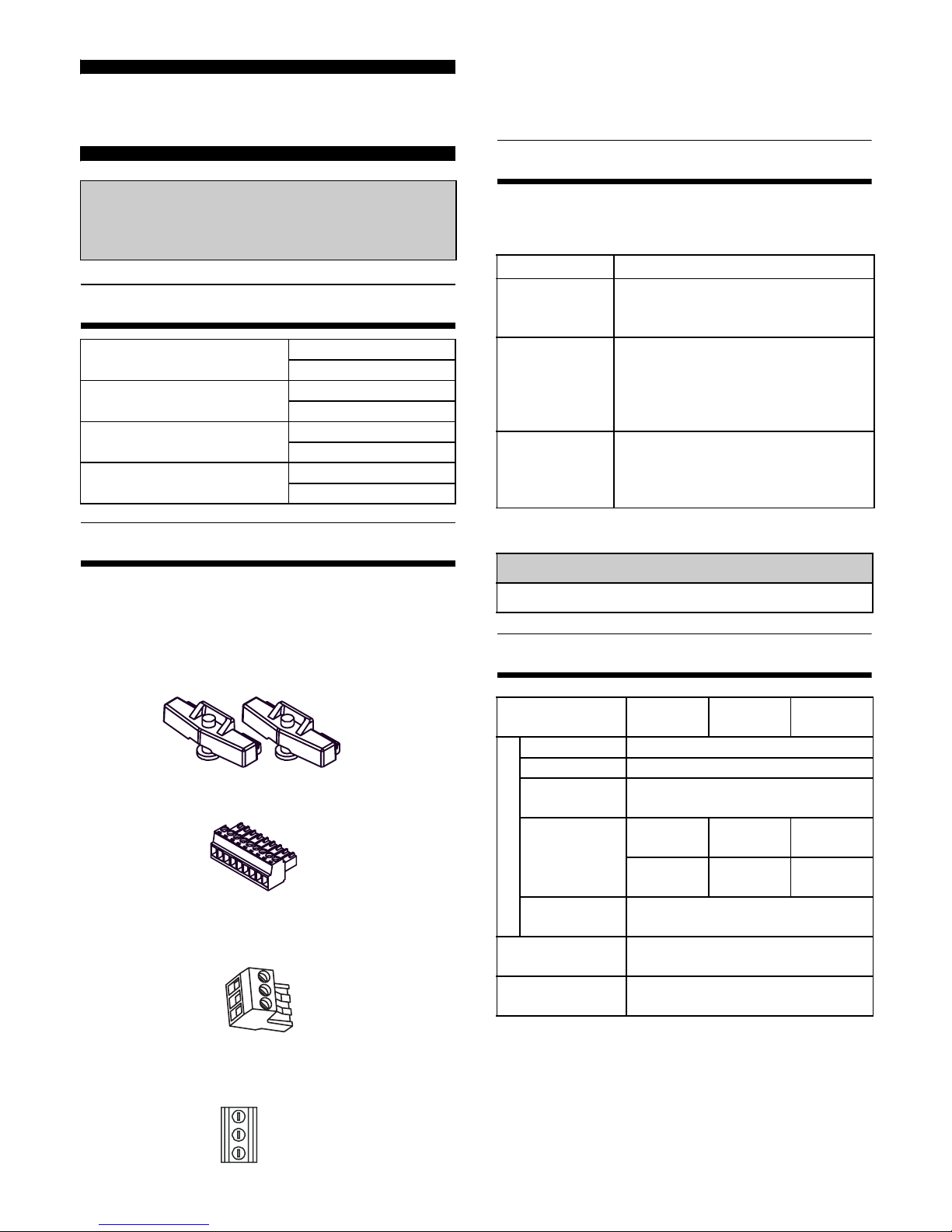
Package Contents
(1) GP Unit (1)
(2) Installation Guide (1) <This Guide>
(3) Warning/Caution Information (1)
(4) Installation Gasket (1, attached to the GP unit)
(5) Installation Fasteners (Set of 2)
(6) COM I/F Connector (1)
(For RS-232C and RS-422/485 types)
(7) DC Power Supply Connector (1)
(For the Ethernet type and a portion of models*1)
(Attached to unit)
*1 Not included with models that have the following
type of power connector.
This unit has been carefully packed, with special
attention to quality. However, should you find anything damaged or missing, please contact your local
GP distributor immediately.
About the Manual
This manual describes wiring and installation
procedures. For more detailed information, refer to
the manuals indicated below.
The manuals can be selected from the help menu of
GP-Pro EX or downloaded from Pro-face Home Page.
Electrical Specifications
Please read the "Warning/Caution
Information" on the attached sheet
before using the product.
RS-232C type
GP4105G1D
GP4105W1D
RS-422/485 type
GP4106G1D
GP4106W1D
RS-485 (isolation) type
GP4107G1D
GP4107W1D
Ethernet type
GP4104G1D
GP4104W1D
Manual Contents
GP-4100 Series
Hardware
Manual
Specifications, dimensions,
accessories, system design, overseas
standards, and other details.
Device/
PLC Connection
Manual
System configuration of connected
devices (PLCs and other devices),
communication settings examples,
connection wiring diagram, and
other details.
Maintenance/
Troubleshooting
• Troubleshooting
Help for solving problems.
• Maintenance
Details on the GP unit’s Offline Mode
URL
http://www.pro-face.com/otasuke/
GP4104*
GP4105*
GP4106* GP4107*
Power Supply
Input Voltage
DC24V
Rated Voltage
DC19.2 to 28.8V
Allowable
Voltage Drop
3ms or less
Power
Consumption
6.0 W or
less
6.2 W or
less
6.5 W or
less
2.7 W or
less
*1
*1 When power is not supplied to USB devices.
3.0 W or
less
*1
3.4 W or
less
*1
In-Rush
Current
30 A or less
Voltage
Endurance
AC1,000V, 20mA for 1 min (between
charging and FG terminals)
Insulation
Resistance
DC500V, 10MΩ or more (between
charging and FG terminals)
Page 2
2
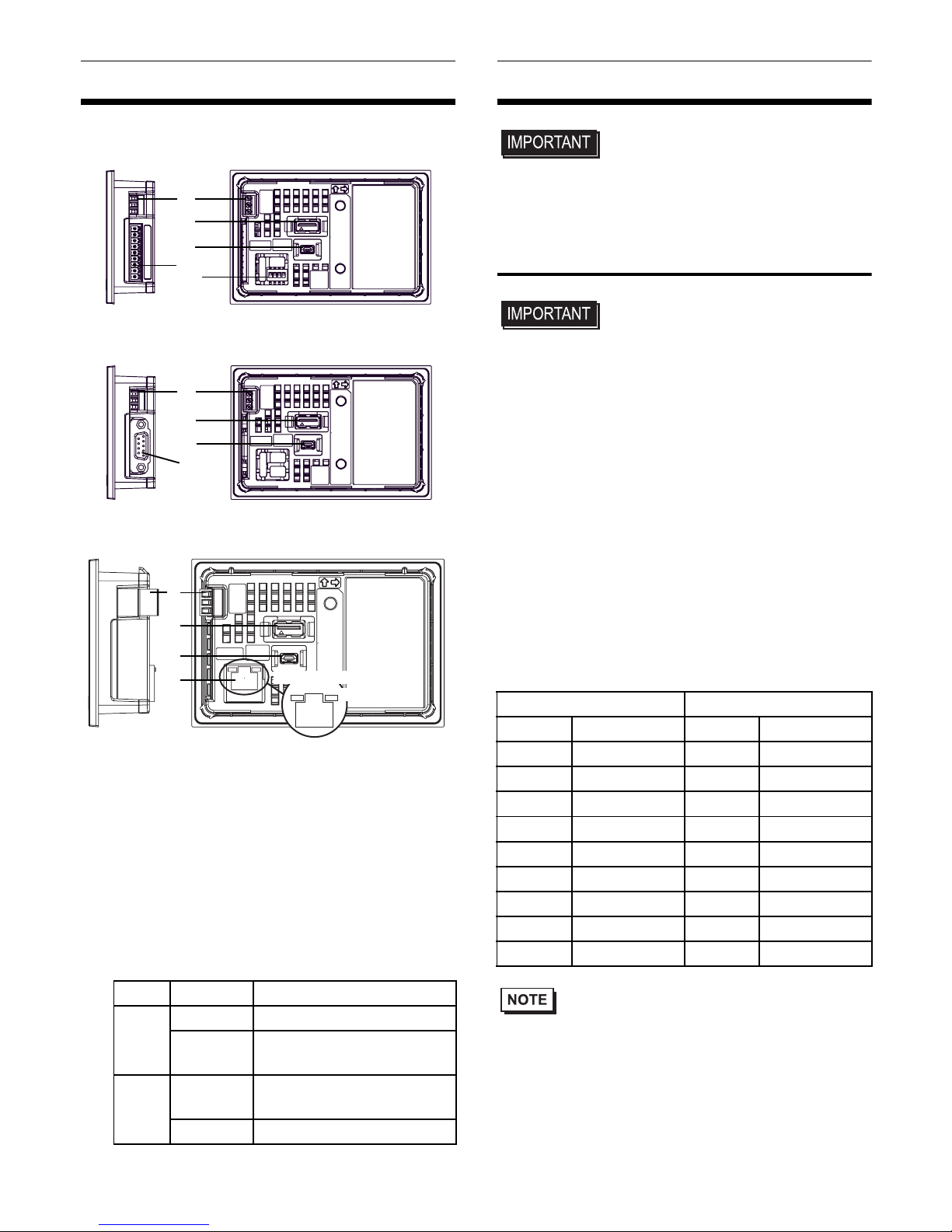
Part Names and Functions
Ethernet type
(A) Power Connector
(B) Serial Interface (COM1)
(C) USB (Type A) Interface (USB1)
(D) USB (mini B) Interface (USB2)
(E) DIP Switch (SW1)
Only on RS-422/485 type.
(F) Ethernet Interface
The Ethernet transmission interface (10BASET/100BASE-TX). An RJ-45 type modular jack
connector (8-pole) is used.
External Interfaces
• For instructions on how to connect to other
devices, always refer to the "GP-Pro EX Device/
PLC Connection Manual".
1. Serial Interface
•
For detailed information on pins, refer to the GP4100 Series Hardware Manual.
• The serial interface of the RS-232C and RS-422/
485 types is not isolated. Always connect pin #5
SG (Signal Ground) to the connected device,
especially if the connected device is also not
isolated. Failure to do so may damage the RS232C/RS-422/RS-485 circuit.
• An SG (Signal Ground) and FG (Frame Ground)
are connected internally in the RS-232C and RS422/485 types. When connecting an external
device to the GP using the SG terminal, be sure
to check that no short-circuit loop is created when
you setup the system.
RS-232C and RS-422/485 Types
Included COM I/F connector
(9-pin, 2-piece terminal block)
• A termination resistor can be set using the DIP
Switch (4-bit) on the rear of the RS-422/485 type.
Factory default settings are all set to “OFF” (no
termination resistor). Check the termination
resistor required for connection to the connected
device (PLC) and install if necessary. For detailed
information, refer to the GP-Pro EX Device/PLC
Connection Manual.
LED
Status Indicates
LINK
Green ON Data transmission available
Green OFF
No connection or subsequent transmission failure
ACT
Green ON
Data transmission is
occurring.
Green OFF
No data transmission
Rear (RS-422/485 type )
A
C
D
B
Right side
Right side
Rear
A
C
D
B
RS-485 (isolation) type
RS-232C type, RS-422/485 type
E
Right side
Rear
A
C
D
F
ACT LED
LINK LED
RS-232C type RS-422/485 type
Label
Signal Name
Label
Signal Name
CI CI(RI) CSB CSB
CD CD CSA CSA
CS CS(CTS) ERB ERB
RS RS(RTS) ERA ERA
SG SG SG SG
DR DR(DSR) RDB RDB
ER ER(DTR) RDA RDA
RD RD(RXD) SDB SDB
SD SD(TXD) SDA SDA
Page 3
3
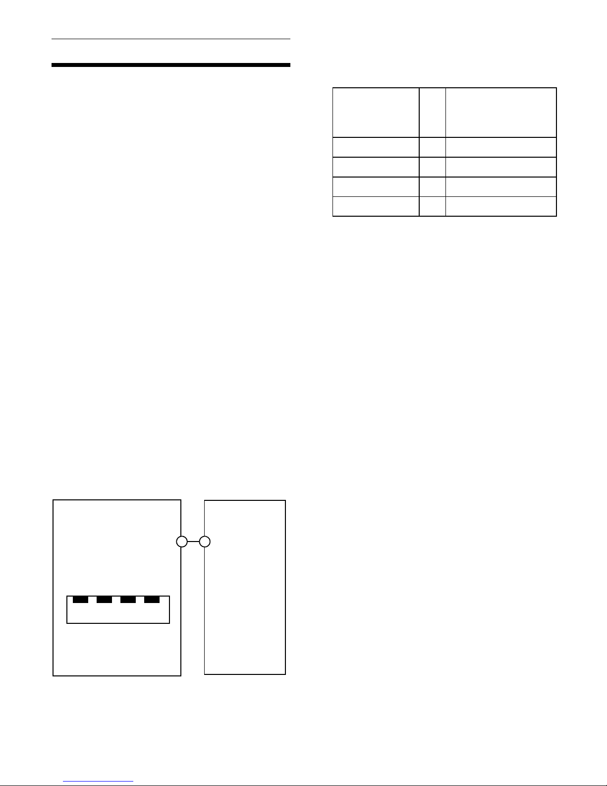
Communications Cable Specifications
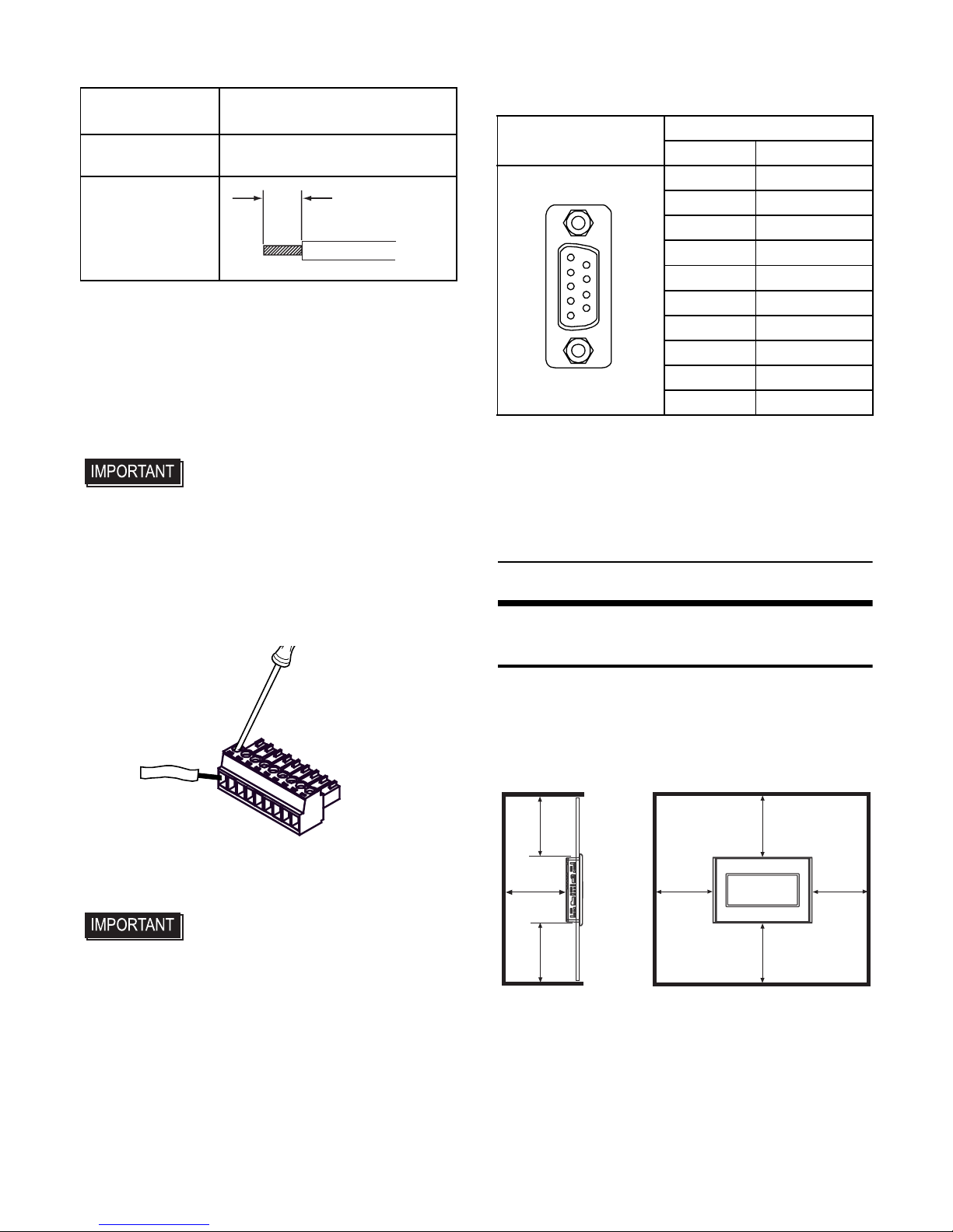
Wiring the COM Interface Connector
• Always ensure that the connector has been
removed from the GP unit before wiring the connector. Failure to do so may result in electric
shock.
(1) Use a flat-blade screwdriver (Size 0.4 X 2.5) to
loosen the terminal screws.
(2) Strip the communications cable, and attach it to
the terminal connector.
(3) Use a flat-blade screwdriver to tighten the
appropriate terminal screws on the terminal
connector from step 2.
• The torque required to tighten these screws is
0.196N•m
(1.735[Lb•in])
.
(4) Insert the connector into the GP unit’s serial
interface.
RS-485 (isolation) type
D-Sub 9-pin socket type connector
Installations
1. Installation Requirements
• For easier maintenance, operation, and improved
ventilation, be sure to install the GP at least
100mm [3.94in.] away from adjacent structures
and other equipment.
• Be sure that the surrounding air temperature and
the ambient humidity are within their designated
ranges. (Surrounding air temperature: 0 to 50°C,
Ambient humidity: 10 to 90%RH, Wet bulb
temperature: 39°C max.) When installing the GP
on the panel of a cabinet or enclosure,
“Surrounding air temperature” indicates both the
panel face and cabinet or enclosure’s internal
temperature.
Communications
Cable Diameter
*1
*1 When inserting two wires into one terminal con-
nector, the simple wire diameter is 0.08 to
0.5mm
2
(28 - 22 AWG), and the stranded wire di-
ameter is 0.08 to 0.75mm
2
(28 - 20 AWG).
0.14 to 1.5mm
2
(28 - 16 AWG)
Conductor Type
Simple or Stranded Wire
*2
*2 If the Conductor’s end (individual) wires are not
twisted correctly, the end wires may either short
against each other, or against an electrode.
Conductor
Length
7mm
[0.28in]
(2)
Insert the wire into the
terminal connector.
Ter mi na l
Connector
(1)
Use a flat-blade
screwdriver to
loosen the terminal
screws.
(3)
Use a flat-blade
screwdriver to tighten
the terminal screws.
Pin Connection
RS-485 (isolation) type
PIN # Signal Name
(GP unit side)
1NC
2NC
3LINE(+)
4 RS(RTS)
5SG
*1
*1 The SG and FG terminals are isolated.
65V
*2*3
*2 When providing power of termination resistor via
the Siemens PROFIBUS, power cannot be connected to the Device/PLC.
*3 The 5V output for Pin # 6 is not protected against
overcurrent.
7NC
8LINE(-)
9NC
Shell FG
*1
1
5
6
9
100
[3.94]
100
[3.94]
100
[3.94]
100
[3.94]
Unit: mm [in.]
100
[3.94]
100
[3.94]
100
[3.94]
Page 4
4
•
Be sure that heat from surrounding equipment does not cause
the GP to exceed its standard operating temperature.
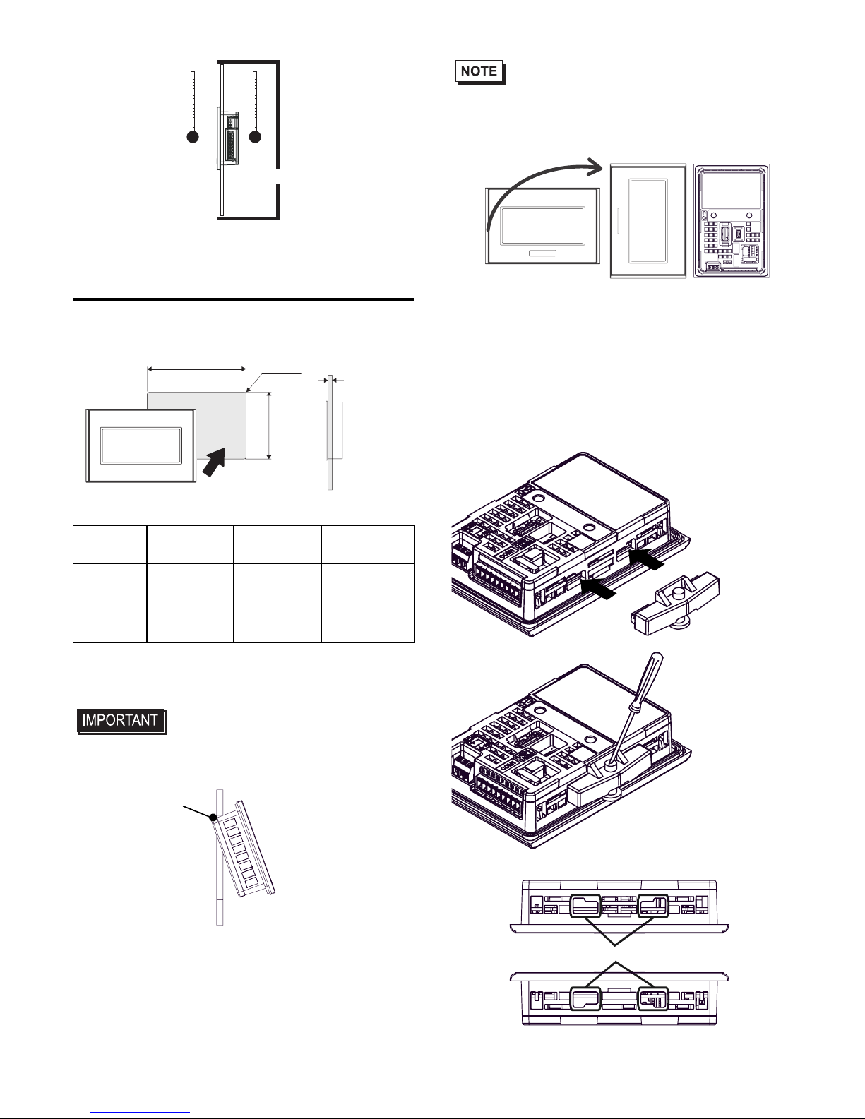
2. GP Installation
(1) Cut a hole in the panel according to the GP unit
panel cutout dimensions.
(2) Confirm that the installation gasket is attached
to the GP unit and then place the GP unit into
the Panel from the front.
•
GP unit has two projections*1 on the top to prevent
falling during installation. Please insert the GP unit into
the panel at an angle to avoid hitting the projections.
*1 GP units with Rev.1 or higher have projec-
tions. More information, please see the
nameplate on the GP unit.
•
It is strongly recommended that you use the installation gasket, since it absorbs vibration in addition
to repelling water.
For the procedure for replacing the installation gasket, refer to “GP-4100 Series Hardware Manual”.
• When mounting the GP unit vertically, ensure that
the left side of the unit faces up (i.e. the power
connector and serial interface should be at the
bottom).
(3) Press the installation fastener hooks securely
into the insertion slots on the GP unit. (Press
the hooks in again to release the lock and
remove the installation fasteners.)
(4) Tighten the installation fasteners with a screw-
driver. There are two insertion slots on both the
top and bottom of the GP unit.
GP X Y
Panel
thickness
GP-4100
Series
105.0
[4.13 ]
66.0
[2.60 ]
1.0 [0.04]
to
5.0 [0.20]
Panel Face
Inside Cabinet
X
Panel
thickness
GP
Y
r≤3 [0.12]
Unit: mm [in.]
+1
-0
+0.04
-0
+1
-0
+0.04
-0
Projections
Insert GP at an angle.
Mounted
Horizontally
Front and Rear Views
when Mounted Vertically
(3)
Press the hooks
securely into
the insertion
slots.
(4)
Tighten the
screw with a
screwdriver
To p
Bottom
Insertion Slots
Page 5
5
• Tightening the screws with too much force can
damage the GP unit’s plastic case.
• In order to guarantee water repelling effect the
necessary torque is 0.52N•m [4.60Lb•in].
Wiring
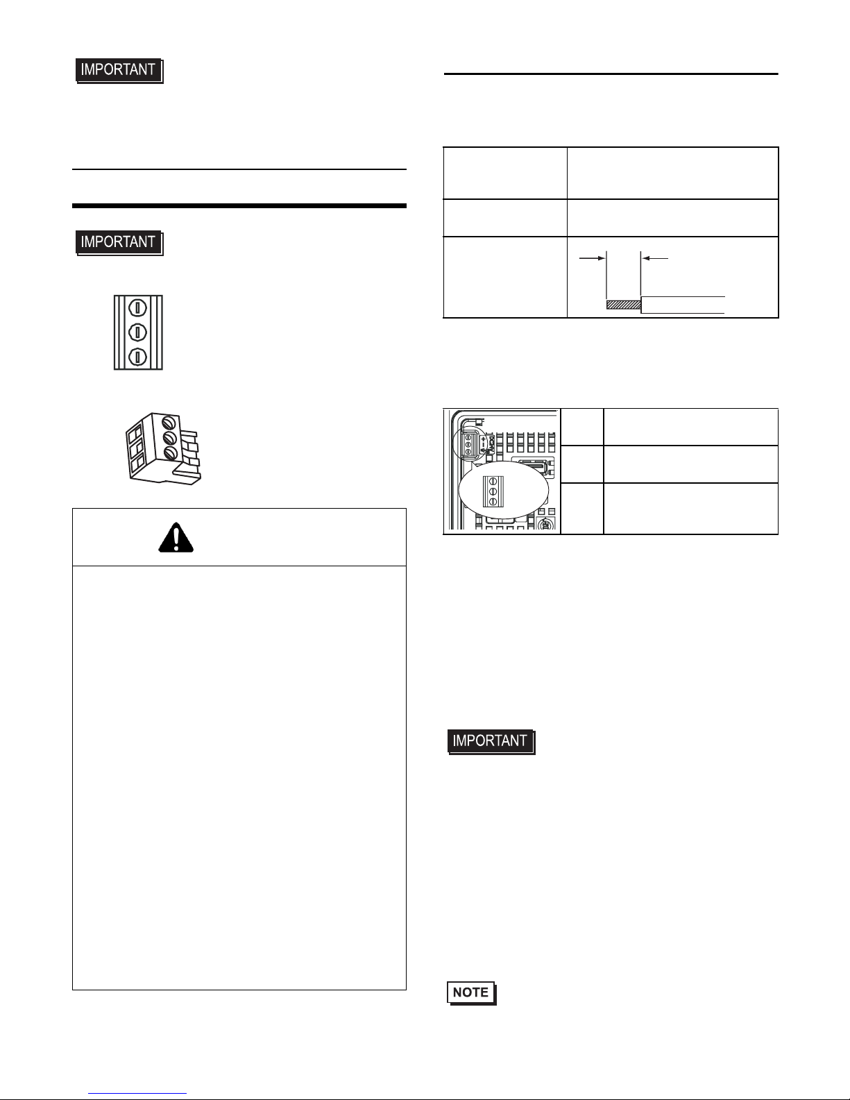
• If the power connector is the following type,
please read "1. Wiring the Power Cord No.1".
•
If the power connector is the following type, please
read "2. Wiring the Power Cord No.2".
1. Wiring the Power Cord No.1
Power Cord Specifications
Use copper conductors only.
Power Connector Specificati
ons
Connecting the GP Power Cord
(1) Confirm that the GP unit’s Power Cord is
unplugged from the power supply.
(2) Use a flat-blade screwdriver (Size 0.4 X 2.5) to
loosen the terminal screws.
(3) Strip the power cord, and attach it to the power
connector.
(4) Use a flat-blade screwdriver to tighten the
appropriate terminal screws on the terminal
connector from step 3.
•
The torque required to tighten these screws is
0.28N
•
m (2.5 [Lb•in]).
•
The power connector cannot be removed because
it is mounted to GP unit. Do not attempt to
remove or tamper with the power connector. It
may damage the power connector.
•
Be sure to loosen the terminal screws before pulling out the power cord. The power connector may
be damaged by pulling the power cord when
attached to the power connector.
• Do not solder the cable connection.
Doing so may damage the unit due to abnormal
heat or cause a fire.
• Be sure to twist the power cords together, up to
the power connector.
WARNING
HAZARD OF ELECTRIC SHOCK
• Prior to connecting the GP unit's power cord
terminals to the power terminal block, confirm
that the GP unit's power supply is completely
turned OFF, via a breaker, or similar unit.
• Supplying a power voltage other than that
specified will damage the power source and
the GP unit.
• Since there is no power switch on the GP
unit, be sure to attach a breaker-type switch
to its power cord.
• When the FG terminal is connected, be sure
the wire is grounded.
Failure to follow these instructions will result
in death or serious injury.
Power Cord
Diameter
Simple Wire: 0.75 to 1.5mm
2
Stranded Wire: 0.75 to 1mm
2
(18 - 16 AWG)
Conductor type
Simple or Stranded Wire
*1
*1 If the Conductor’s end (individual) wires are not
twisted correctly, the end wires may either short
against each other, or against an electrode.
Conductor
Length
•
•
•
•
+ 24V
-
0V
FG
Grounding Terminal connected to the GP chassis
5mm
[0.2in]
-
+
FG
GP Rear
Page 6
6
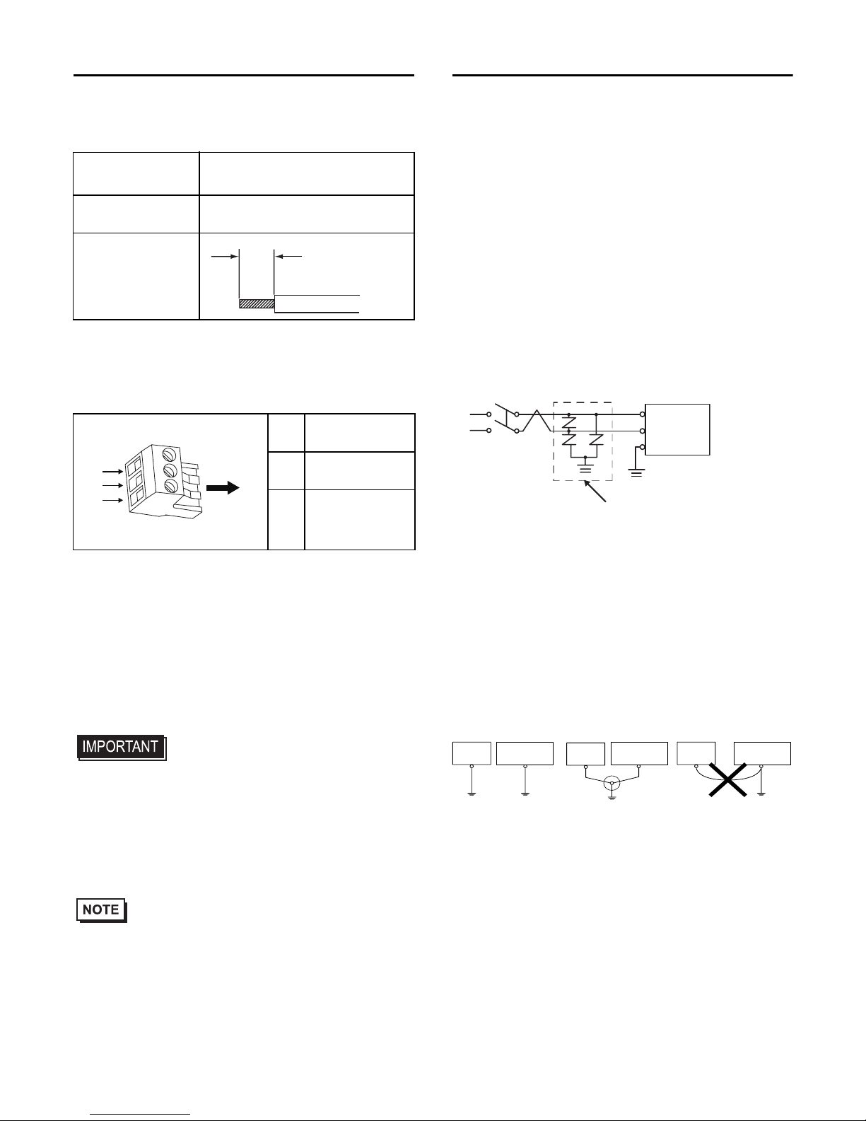
2. Wiring the Power Cord No.2
Power Cord Specifications
• Use copper conductors only.
Power Connector Specifications
Connecting the GP Power Cord
(1) Confirm that the power cord is unplugged from
the power supply.
(2) Check the rated voltage, and remove the sticker
on the power connector that reads "DC 24V".
(3) Remove the power connector (plug) from the
main unit.
(4) Strip the membrane of the power cord, and con-
nect them to the Power Connector.
•
Use a flat-blade screwdriver (Size 0.4 x 2.5 mm
(0.015 to 0.098 in.)) to tighten the terminal screws.
The torque required to tighten these screws is
0.22 to 0.25N
•
m [1.95 to 2.2Lb•In.].
•
Do not solder the cable connection. Doing so may
damage the unit due to abnormal heat or cause a fire.
(5) Reattach the Power Connector (plug).
• Be sure to twist the power cords together, up to
the power connector.
3. Wiring Cautions
Improving Noise/Surge Resistance
• The GP unit’s power supply cord should not be
bundled with or kept close to main circuit lines
(high voltage, high current), power lines, or input/
output lines, and their various systems should be
kept separate. When power lines cannot be wired
via a separate system, use shielded cables for
input/output lines.
•
Make the power cord as short as possible, and be
sure to twist the ends of the wires together (i.e. twisted
pair cabling) from close to the power supply unit.
• If there is an excess amount of noise on the
power supply line, connect a noise reducing
transistor before turning on the power.
• Connect a surge absorber to handle power
surges. Be sure to ground the surge absorber
(E1) separately from the GP unit (E2).
Short Circuit Prevention
• The SG (signal ground) and FG (frame ground)
terminals are connected internally in the GP unit.
When connecting the SG line to another device,
be sure that no shorting loops are formed.
Grounding
• Use an exclusive grounding wire with a grounding
resistance of 100Ω or greater and a wire of 2mm
2
or thicker, or your country’s applicable standard.
Power Cord
Diameter
0.75 to 1.5mm
2
(18 - 16 AWG)
Conductor type
Simple or Stranded Wire
*1
*1 If the Conductor’s end (individual) wires are not
twisted correctly, the end wires may either short
against each other, or against an electrode.
Conductor
Length
+24V
-
0V
FG
Grounding Terminal connected to
the GP chassis
7mm
[0.3in]
-
+
FG
Insertion
Direction
Lightening Surge Absorber
E1 E2
FG
GP
GP unit
Other
Equipment
Exclusive Grounding
(Best)
GP unit
Other
Equipment
GP unit
Other
Equipment
Common Grounding
(OK)
Common Grounding
(Not OK)
Page 7
7
UL/c-UL Approval
<Cautions>
Be aware of the following items when building the
GP unit into an end-use product:
• For use on a flat surface of a Type 4X (Indoor Use
Only) and/or Type 13 Enclosure.
• The temperature rating of field installed
conductors: 75°C only.
• Must be used with a Class 2 Power Supply. (24
VDC)
• For use in Pollution Degree 2 environment, or
equivalent.
• Surrounding air temperature rating 50°C
maximum or equivalent.
<Compliance and Handling Cautions in Hazardous
Locations>
• SUITABLE FOR USE IN CLASS I, DIVISION 2,
GROUPS A, B, C AND D HAZARDOUS
LOCATIONS, OR NONHAZARDOUS
LOCATIONS ONLY.
• WARNING - EXPLOSION HAZARD SUBSTITUTION OF ANY COMPONENTS MAY
IMPAIR SUITABILITY FOR CLASS I, DIVISION
2.
• WARNING - EXPLOSION HAZARD - DO NOT
DISCONNECT EQUIPMENT WHILE THE
CIRCUIT IS LIVE OR UNLESS THE AREA IS
KNOWN TO BE FREE OF IGNITABLE
CONCENTRATIONS.
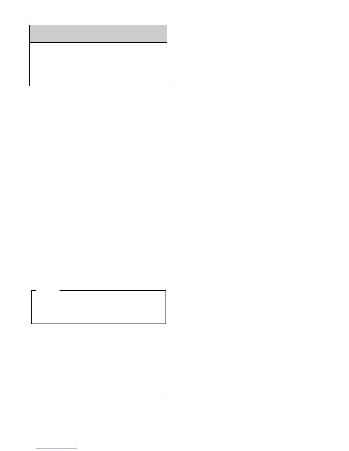
• Control Drawing of USB port A (USB1) I/F
The information below concerns the use of the
USB I/F used in Class I, Division 2 Groups A, B,
C, and D hazardous locations (from Doc No.
3910017-USB).
Notes:
1. Nonincendive Circuit Parameters:
USB I/F:
Voc = 5.25 V
Isc = 0.7 A
Ca = 16 µF
La = 10 µF
2. Selected Associated Nonincendive Field Wiring
Apparatus shall satisfy the following:
3. If the electrical parameters of the cable are
unknown, the following values may be used:
Capacitance = 60 pF/ft
Inductive = 0.20 µH/ft
4. Nonincendive Field Wiring must be installed in
accordance with article 501.10(B) of the National
Electrical Code ANSI/NFPA 70.
5. Nonincendive Field Wiring Apparatus shall not contain or be connected to another source of power.
• Mini USB port (USB2) is for temporary connection
only during maintenance and setup of the device.
Do not use, connect, or disconnect unless area is
known to be non-hazardous. Connection or
disconnection in an explosive atmosphere could
result in an explosion.
USB Pin Description
1. Vcc
2. D-
3. D+
4. GND
(See Note 1 for details)
Shield GND
Nonincendive
Field
Wiring
Apparatus
1 2 3 4
Associated Nonincendive Field Wiring
Apparatus
Nonincendive
Field
Wiring
Apparatus
-
Associated
Nonincendive Field
Wiring Apparatus for
Graphic Panel
Voc ≤ Vmax
Isc ≤ lmax
Ca ≥ Ci + C cable
La ≥ Li + L cable
Page 8
8
Digital Electronics Corporation
8-2-52 Nanko-higashi
Suminoe-ku, Osaka 559-0031
JAPAN
TEL: +81-(0)6-6613-3116
FAX: +81-(0)6-6613-5888
http://www.pro-face.com
The information in this document is subject to
change without notice.
© Copyright 2009 Digital Electronics Corporation. All
rights reserved.
Inquiry
Do you have any questions about difficulties with
your GP?
Please access our site anytime that you need
help with a solution.
http://www.pro-face.com/otasuke/
Please be aware that Digital Electronics Corporation shall not be held liable by the user for any
damages, losses, or third party claims arising
from the uses of this product.
Note
 Loading...