

Page 1

Device/PLC Connection
Manuals
About the Device/PLC Connection Manuals
Prior to reading these manuals and setting up your device, be sure to read the
"Important: Prior to reading the Device/PLC Connection manual" information. Also,
be sure to download the "Preface for Trademark Rights, List of Units Supported, How
to Read Manuals and Documentation Conventions" PDF file. Furthermore, be sure
to keep all manual-related data in a safe, easy-to-find location.
Page 2
Hitachi Industrial Equipment System - Ethernet
7.8 Hitachi Industrial Equipment System
With Hitachi HIDIC-H Ethernet Protocol units, when the same
project file is used on multiple GP/GLC units, the system may malfunction. When using multiple GP/GLC units, create and maintain only one unique project file for each GP/GLC unit.
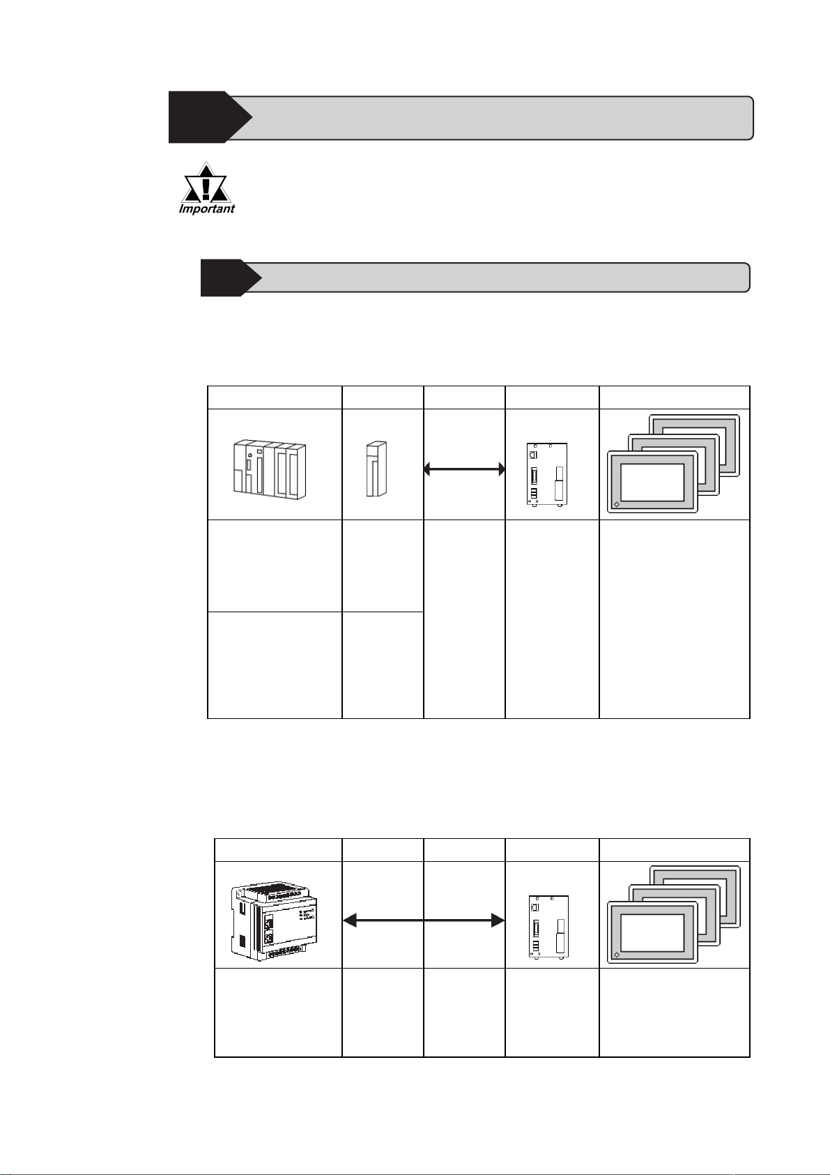
7.8.1 System Structure for Ethernet Connection
This section explains the system structures for the Ethernet connection between
Hitachi Industrial Equipment System PLCs and GP units.
HIDIC H Series
CPU LinkI/F Cables Unit GP
Ethernet Unit
H4010(CPU3-40H)
H2002(CPU2-20H)
H1002(CPU2-07H)
H702(CPU2-20H)
H302(CPU2-40H)
EH-150(EH-CPU308A)
EH-150(EH-CPU316A)
EH-150(EH-CPU448)
EH-150(EH-CPU448A)
EH-150(EH-CPU516)
EH-150(EH-CPU548)
LAN-ETH
EH-ETH
Ethernet cable
(compatible
with the
IEEE802.3)
*2
Pro-face Ethernet
I/F Unit
GP070-ET41
GP377-MLTE11
GP377-MLTE41
GP077-MLTE41
GP/GLC Series
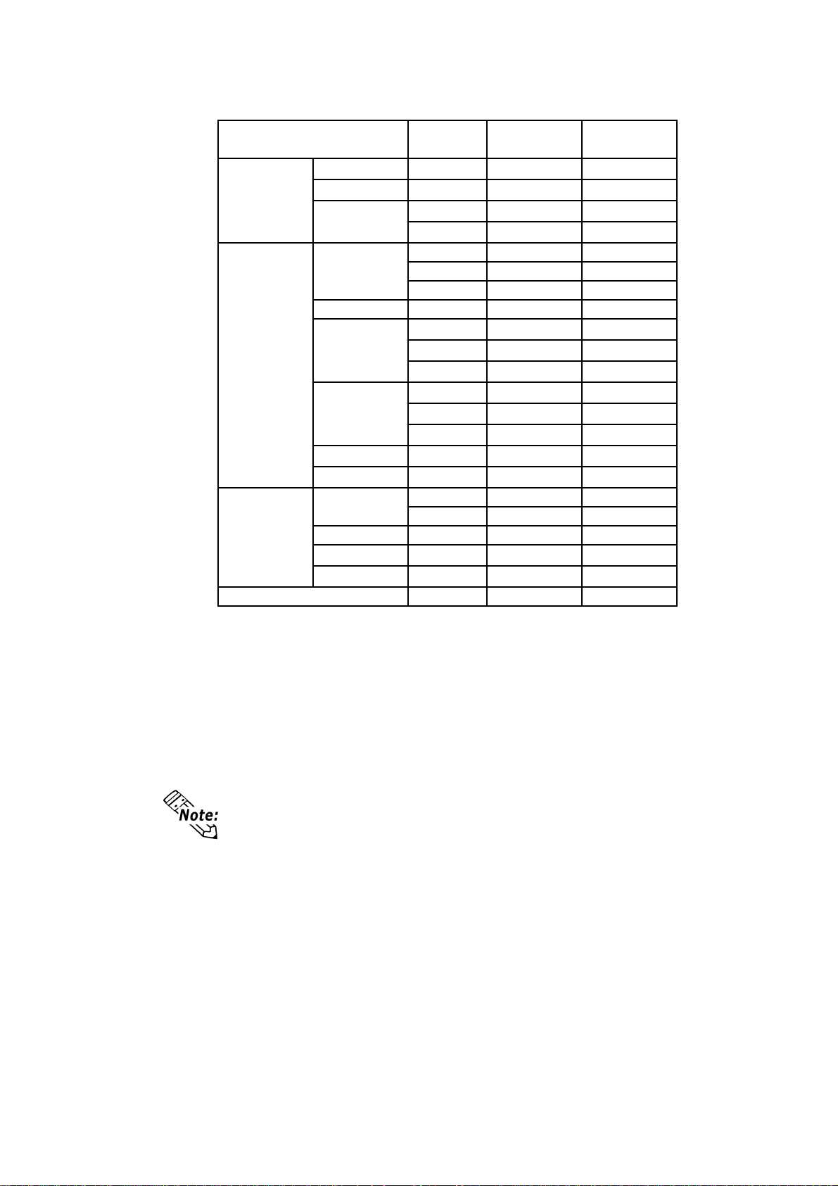
* 1 Refer to the following table for compatible GP/GLC units and Ethernet con-
nection information.
* 2 The versions of the connectable EH-ETH are as follows;
Hardware Rev.01, Software Rev.06 and more
Web Controller
CPU LinkI/F Cables Unit GP
*1
EH-WD10DR Ethernet port
on CPU unit
Ethernet cable
(compatible
with the
IEEE802.3)
* 1 Refer to the following table for compatible GP/GLC units and Ethernet con-
nection information.
GP-PRO/PBIII for Windows Device/PLC Connection Manual
Ethernet I/F Unit
GP070-ET41
GP377-MLTE11
GP377-MLTE41
GP077-MLTE41
GP/GLC Series
*1
1
Page 3
Hitachi Industrial Equipment System - Ethernet
GP77R Series
GP2000 Series
ST Series
Series Name
GP-377R Series GP-377RT
GP-477R Series GP-477RE
GP-577R Series
GP-2300 Seri es
GP-2400 Seri es GP-2400T
GP-2500 Seri es
GP-2501 Seri es
GP-2600 Seri es GP-2600T
GP-2601 Seri es GP-2601T
GLC-2300 Ser iesGLC2000 Seri es
GLC-2400 Ser ies GLC-2400T
GLC-2500 Ser ies GLC-2500T
GLC-2600 Ser ies GLC-2600T
Product Name
GP-577RS
GP-577RT
GP-2300L
GP-2300S
GP-2300T
GP-2500L
GP-2500S
GP-2500T
GP-2501L
GP-2501S
GP-2501T
GLC-2300L
GLC-2300T
ST403
Optional
Ethernet I/F Unit
*1 *2
*2
*2
*2
x
x
x
x
*3 *4
*3 *4
*3 *4
*2 *3
*2 *3
*2 *3
*3 *4
*2 *3
x
x
x
*3 *4
*3 *4
x
Built-in
Ethernet Port
x
x
x
x
x
x
x
x
*1 Only the Multi Unit can be used.
*2 The 2-Way Driver (Pro-Server, GP-Web and others) cannot be used.
*3 When using optional Ethernet I/F unit, a bus conversion unit (PSL-CONV00)
is required.
* 4 Using the optional Ethernet I/F Unit allows you to set up separate Class and
Net No.s for 2-Way Driver applications (Pro-Server, GP-Web and others)
and the PLC. When doing this, data transfer with the PLC is performed through
the optional Ethernet I/F Unit.
For cable connections, refer to the user's manual for each optional unit.
For the GP2000 and GLC2000 series units, however, refer to the User
Manual for the main unit.
2
GP-PRO/PBIII for Windows Device/PLC Connection Manual
Page 4
Connection Structure
Hitachi Industrial Equipment System - Ethernet
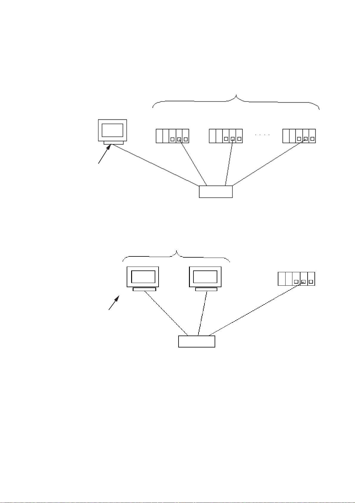
<1 : n connection>
GP Series
Optional Units
•EGP070-ET41
•EGP377-MLTE11
•EGP377-MLTE41
•EGP077-MLTE41
<n : 1 connection>
UDPConnection: Up to 32 units
TCPConnection: Up to 3 units(GP2000/GLC2000 series)
Up to 2 units (GP77R series)
HIDIC H Series
10BASE-T Cable
HUB
Max. of 2 units (When using Web Controller or EH-150, max. is 4 units.)
GP Series GP Series HIDIC H Series
Optional Units
•EGP070-ET41
•EGP377-MLTE11
•EGP377-MLTE41
•EGP077-MLTE41
10BASE-T Cable
HUB
GP-PRO/PBIII for Windows Device/PLC Connection Manual
3
Page 5

Hitachi Industrial Equipment System - Ethernet
<Multiple CPU Links>
PLCs on Ethernet Network:
UDP Connection: Up to 32 units
TCP Connection: Up to 3 units (GP2000/GLC2000 series)
Up to 2 units (GP77R series)
PLC using CPU Link: Up to 64 units
Optional Units
•EGP070-ET41
•EGP377-MLTE11
•EGP377-MLTE41
•EGP077-MLTE41
10BASE-T Cable
HUB
Ethernet Unit
HIDIC H Series
Ethernet Unit
HIDIC H Series
CPU Link Unit
CPU Link
CPU Link Unit
CPU Link Unit
4
GP-PRO/PBIII for Windows Device/PLC Connection Manual
Page 6
Hitachi Industrial Equipment System - Ethernet
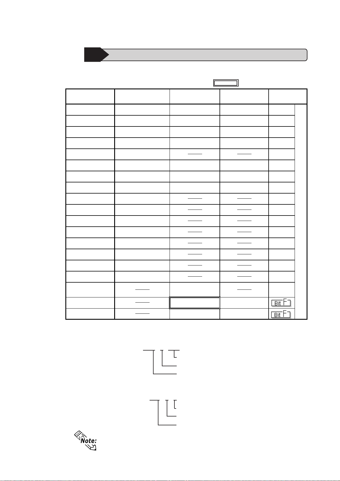
7.8.2 Supported Devices
The following list shows the range of devices supported by the GP .
HIDIC H Series
Device Bit Address Word Address
External Input X0000 ~ X05A95 WX0000 ~ WX05A7 DX0000 ~ DX05A6
External Output Y00000 ~ Y05A95 WY0000 ~ WY05A7 DY0000 ~ DY05A6
Remote Input Relay X10000 ~ X49A95 WX1000 ~ WX49A7 DX1000 ~ DX49A6
Remote Output Relay Y10000 ~ Y49A95 WY1000 ~ WY49A7 DY1000 ~ DY49A6
Internal Output R000 ~ R7BF
Level 1 CPU Link L00000 ~ L03FFF WL0000 ~ WL03FF DL0000 DL03FE
Level 2 CPU Link L10000 ~ L13FFF WL10000 ~ WL13FF DL1000 ~ DL13FE
Setup System Area here.
Double W ord
Address
Other
*1
*1
*1
*1
Data Area M0000 ~ M3FFF WM0000 ~ WM3FF DM0000 ~ DM3FE
On Delay Timer TD0000 ~ TD1023
Single Shot Timer SS0000 ~ SS1023
Watchdog Timer WDT0000 ~ WDT1023
Monostable Timer M S0000 ~ MS1023
Accumulation Timer TMR0000 ~ TMR1023
Up Counter CU0000 ~ CU2047
Link Counter RC U0000 ~ RCU2047
Up/Down Counter CT0000 ~ CT2047
Timer/Counter
(elapsed value)
Word Internal Output WR0000 ~ WRC3FF DR0000 ~ DRC3FE
Network Link Area
TC0000 ~ TC2047
WN0000 ~ WN7FFF DN0000 ~ DN7FFE
* 1 Write your data as follows.
E.g. External Input unit No. 1, Slot No. 2, Module Bit No. 34
X 0 1 2 3 4
L/H
Module Bit No. (00 to 95, decimal)
Slot No. (0 to A, hexadecimal)
Unit No. (0 to 5)
E.g. External Input unit No. 1, Slot No. 2, Module Word No. 3.
W X 0 1 2 3
Module W ord No. (0 to 7, decimal)
Slot No. (0 to A, hexadecimal)
Unit No. (0 to 5)
Depending on your CPU, the usable device type and range may differ.
Before using only a CPU, refer to your CPU User Manual.
GP-PRO/PBIII for Windows Device/PLC Connection Manual
5
Page 7
Hitachi Industrial Equipment System - Ethernet
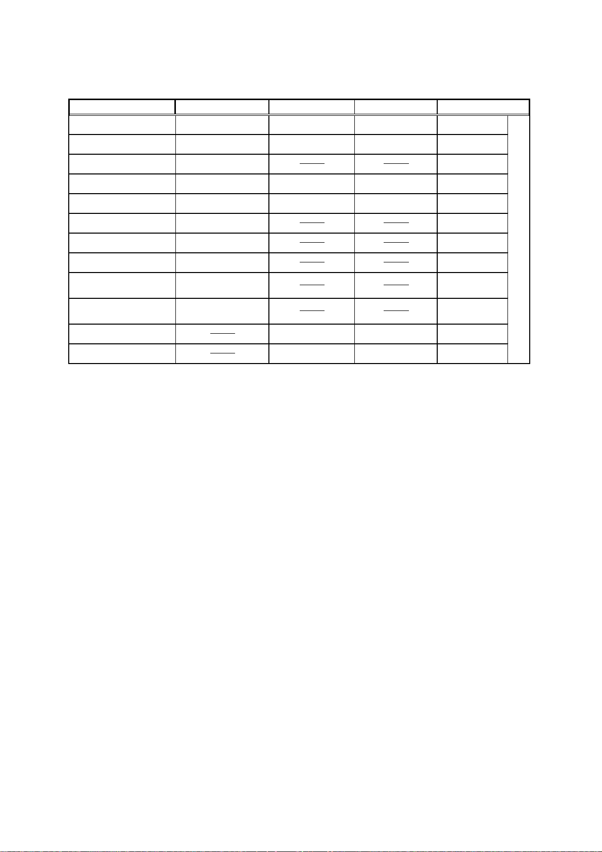
Web Controller
Device Bit Address Word Address Double Word Address Remarks
External Input X000 to X005 WX0 DX0
External Output Y000 to Y005 WY0 DY10
*1
Internal Output R000 to R7BF
Special Internal Output R7C0 to R7FF
Internal Output M0000 to M3FFF WM0000 to WM3FF DM000 to DM3FE
On Delay Timer TD000 t o TD255
Single Shot Timer SS000 to SS255
Up Counter CU000 to CU255
Up/Down Counter -
Up Input
Up/Down Counter -
Down Input
Word Internal Output WR000 to WRFFF DR000 to DRFFE
Word Special Internal Output
CT000 to CT255
CT000 to CT255
WRF000 to WRF1FF DRF000 to DRF1FE
* 1 Data write is not possible.
* 2 The timer and counters used must be designated in the Ladder Program.
* 3 The PLC uses the device names CTU (Up Down Counter Up Input) and CTD
(Up Down Counter Down Input) to handle this data, while the GP/GLC use
the CT designation.
*2*3
*2*3
*2
L/H
*2
*2
When accessing CTU, be sure your Ladder Program uses CTU, and when
accessing CTD, be sure your Ladder Program uses CTD.
6
GP-PRO/PBIII for Windows Device/PLC Connection Manual
Page 8

Hitachi Industrial Equipment System - Ethernet
HIDIC H Series Ethernet Protocol Limitations
When conecting your GP/GLC unit using the HIDIC H Ethernet Protocol to an
HIDIC H Series unit or a W eb Controller, the following limitations apply .
Device Address and Node Number Limitations
When a device address’s size is lar ger than 1024 (1K) or a different Node Number
set, the number of available device addresses will vary . The GP uses internal records
that are used to set the device addresses. These records are limited to 64. For
example, when the WR0 device address is set, a single record is used in the GP.
For detailed examples, refer to the following chart.
Ex1.) Number of records used when designating tag setting numbers.
Remaining
Setting
No.
10 3 WR2049 57
Node
Number
1 1 WR0 63 Uses one record
2 1 WR1024 62 Uses one record
3 2 WR0 61 Uses one record
4 2 W R1024 60 Uses one record
51WM0 60
6 1 WM1024 60
7 1 W R2048 59 Uses one record
8 2 W R2048 58 Uses one record
9 3 W R2048 57 Uses one record
Device
Address
Number of
records in GP-
PRO/PBIII
Note
Since the Node Number and address
range already exist as setti ng No.1, no
records will be used.
Since the Node Number and address
range already exist as setti ng No.2, no
records will be used.
Since the Node Number and address
range already exist as setti ng No.9, no
records will be used.
When the total number of Node Number and Device Addresses exceeds
1024, GP internal records are used. However, if the Node Number and
Device Address are the same type, no record will be used, even if the device
types are different.
Ex2.) When setting tags from WR0000 to WR4000 in W ord Internal Output, since
one record is used for every 1024 addresses, a total of 16 records will be
used.
16384(0x4000)/1024=16
Therefore, when setting the same number of tags for each node, settings for a
total of four nodes can be set.
64/16=4
When the number of records is over 65, the following error message will
appear on GP-PRO/PBIII for Windows.
“Address entry limit reached. No more can be entered.”
GP-PRO/PBIII for Windows Device/PLC Connection Manual
7
Page 9

Hitachi Industrial Equipment System - Ethernet
PLC Device Block Write Restrictions
The GP unit processes data internally by separating data into blocks of 1024 words.
Therefore, when a Block Write is requested that uses 41 or more words and will
exceed the 1024 word limit, the following features cannot be used.
- PLC Device Write using D-Script's Memory Operation Feature
- Write from GP/GLC SRAM to PLC Device using Filing Feature
- Write to LS Area's Read Area
When using these settings, a Host Communication Error may occur.
If an error occurs, separate the data so that the number of words used by the Block
Write is 1024 or less.
8
GP-PRO/PBIII for Windows Device/PLC Connection Manual
Page 10
Hitachi Industrial Equipment System - Ethernet
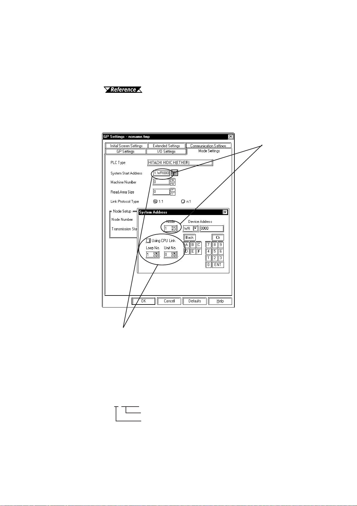
When setting up Parts or T ags from GP-PRO/PBIII for W indows
Before setting up Parts or T ags, Network Information settings must be entered.
Network Information Setting can be set from the [GP SYSTEM SETTING]>[MODE SETTING]->[Network Information] screen.
This manual, 7.7.3 Environment Setup
Specifying the PLC’s Node Address when setting parts or tags allows the specified
PLC’s Device to be read out.
The System Area
and Read Area are
assigned to the PLC
node designated
here.
Depending on if the CPU Link is used or not address
settings will differ.
However, when connecting to a Web Controller, the CPU
Link feature cannot be used.
<When CPU Link is NOT used>
Set the [Using CPU Link] check box to OFF .
1. WM0000
Device Address
Node No.(UDP Connection: 1 to 32, TCP Connection: 1 to 3)
GP-PRO/PBIII for Windows Device/PLC Connection Manual
9
Page 11

Hitachi Industrial Equipment System - Ethernet
<When CPU Link is used>
Set the [Using CPU Link] check box to ON (checked mark). When using the CPU
Link, Loop No. and Unit No. are included in the address.
Ex.)Using Node Address is 1, Loop No. is 2 and Unit No. is 3
1. 2. 3. WM0000
Device Address
CPU Link Unit No. (0 to 63)
CPU Link Loop No. (1 to 2)
Node No. (1 to 32)
When setting up Parts or Tags using GP-PRO/PBIII for Windows, the
PLC’s Node Address can be designated when entering the address. When
the Node Address is not specified, the previously entered numbers will
remain.
10
GP-PRO/PBIII for Windows Device/PLC Connection Manual
Page 12
Hitachi Industrial Equipment System - Ethernet
7.8.3 Environment Setup
GP Settings
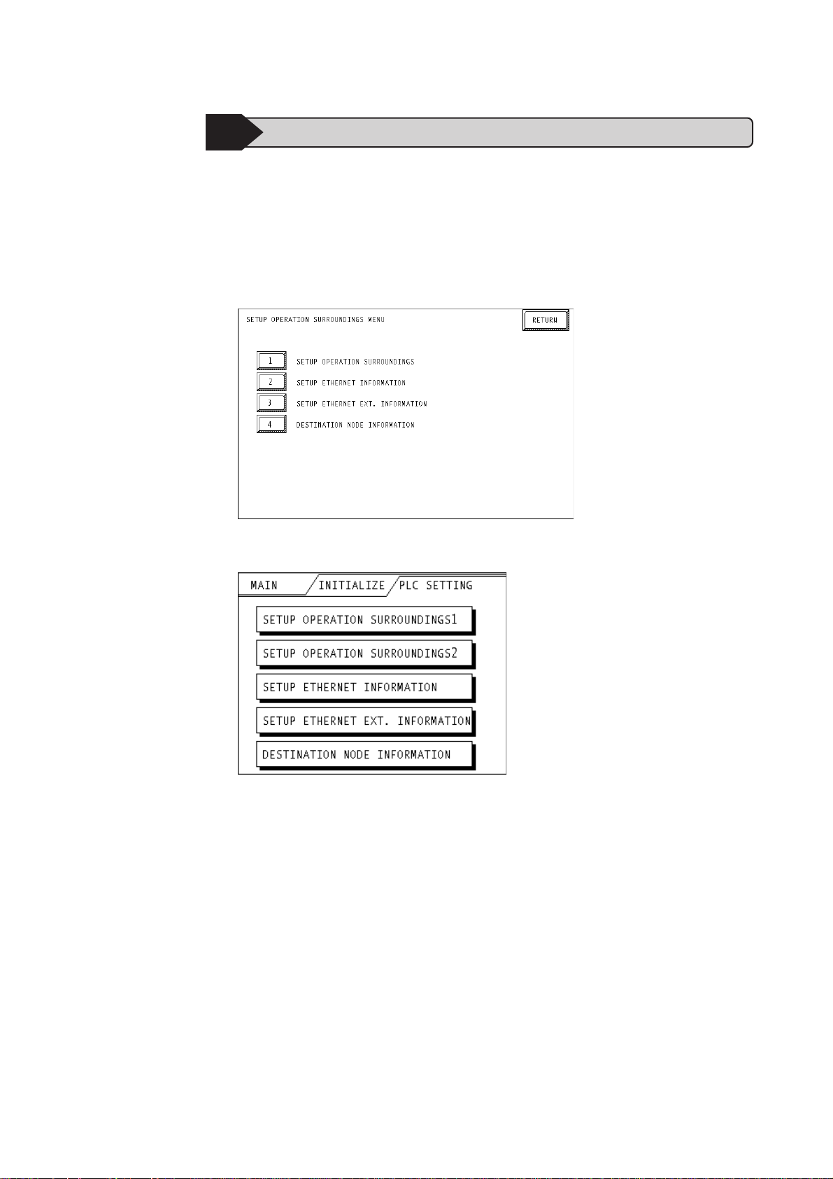
The following screens show the GP/GLC's communication settings, which are required for communication via an Ethernet Network:
SET UP OPERA TION SURROUNDINGS MENU
<GP-477R/GP-577R/GP-2400/GP-2500/GP-2501/GP-2600/GLC2400/GLC2600 Series>
<GP-377R/GP-2300/GLC2300 Series>
GP-PRO/PBIII for Windows Device/PLC Connection Manual
11
Page 13
Hitachi Industrial Equipment System - Ethernet
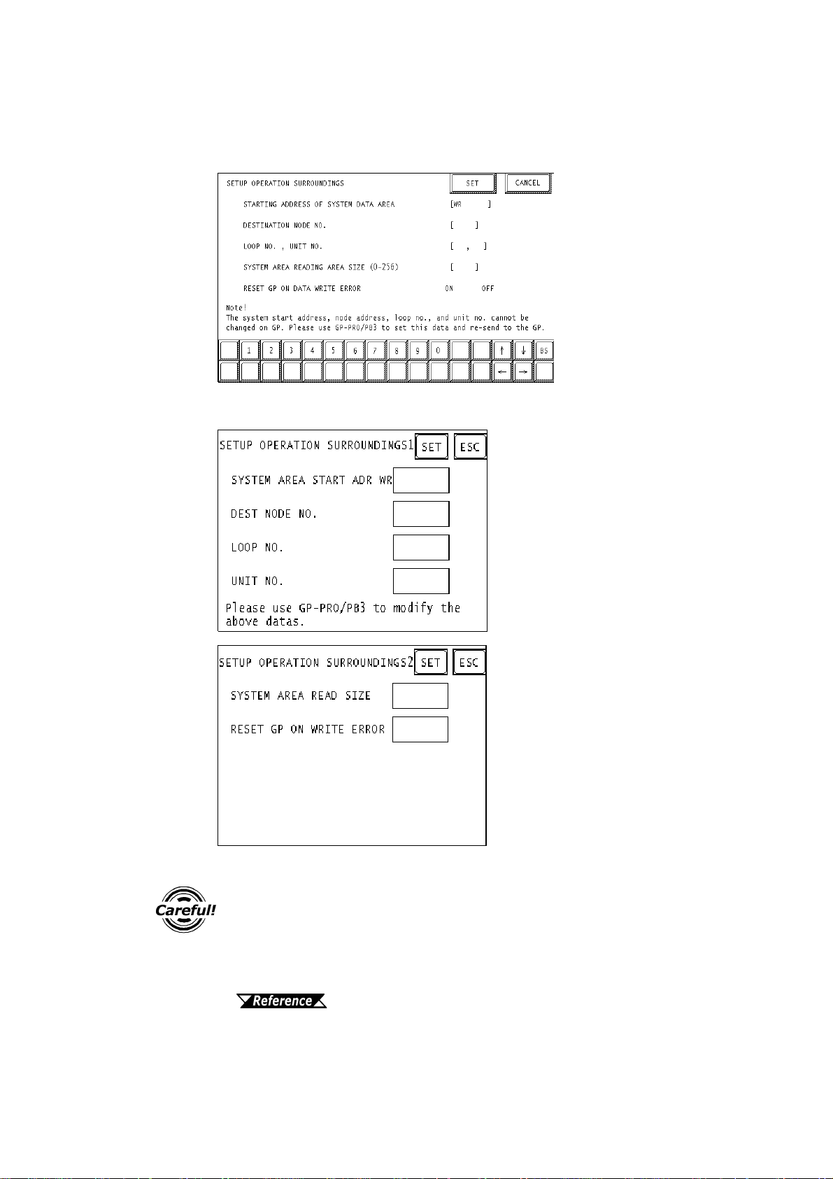
• SET UP OPERA TION SURROUNDINGS
<GP-477R/GP-577R/GP-2400/GP-2500/GP-2501/GP-2600/GLC2400/GLC2600 Series>
<GP-377R/GP-2300/GLC2300 Series>
12
Be sure the Destination Node No. entered are the same as the PLC’s
settings. However, the Destination Node No. settings cannot be
changed from the GP’s OFFLINE mode. Be sure to make these
settings from the GP-PRO/PBIII for Windows [GP SYSTEM SETUP]
-> [MODE SETUP] setting area.
This manual, 7.7.3 Environment Setup GP-PRO/PBIII
for Windows Settings
GP-PRO/PBIII for Windows Device/PLC Connection Manual
Page 14
Hitachi Industrial Equipment System - Ethernet
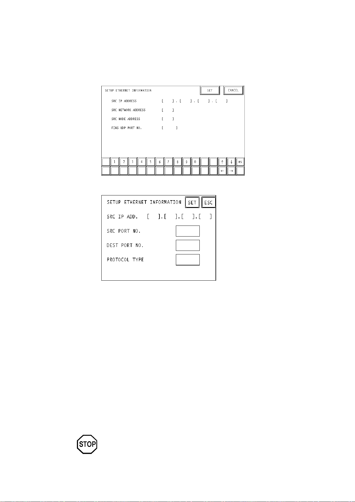
SETUP ETHERNET INFORMA TION
Enter each item in the SET UP ETHERNET INFORMA TION screen.
<GP-477R/GP-577R/GP-2400/GP-2500/GP-2501/GP-2600/GLC2400/GLC2600 Series>
<GP-377R/GP-2300/GLC2300 Series>
• SRC IP ADDRESS (0 to 255)
Enter the IP address for the GP at your station. T o do this, separate the 32 bits
of the IP address into four segments of eight bits each, separate those segments
with a dot and then enter them as decimal numbers.
• SRC PORT NO. (1024 to 65535)
Enter your GP’ s Port No. from 1024 to 65535.
• DEST PORT NO. (1024 to 65535 )
Enter the PLC’ s IP Port No. from 1024 to 65535. Enter the same value as the
PLC’ s Logic Port No.. When connecting a single GP unit to multiple PLC units,
set all PLC units’ Port No. to the same value.
• PROTOCOL TYPE
Select UDP/IP or TCP/IP Communication. When the power is turned ON/
OFF asynchronously , Pro-face recommends UDP/IP Communication.
Do not specify duplicate IP addresses. Contact your network manager about
assigning IP addresses.
GP-PRO/PBIII for Windows Device/PLC Connection Manual
13
Page 15
Hitachi Industrial Equipment System - Ethernet
• When using the built-in Ethernet port on a GP2000 Series unit,
be sure not to enter duplicate "SRC PORT No." values.
• Check the 2-Way driver's "SRC PORT No." Setting via the fol
lowing menu:
GP OFFLINE mode's Main menu [INITIALIZE] -> [SETUP OPERATION SURROUNDINGS] -> [EXTENDED SETTINGS] ->
[SETUP ETHERNET INFORMATION] screen.
• The default value is 8000. The 2-Way driver uses this port and
the following nine ports for a total of 10 (8000 ~ 8009).
• When “SRC IP ADDRESS” is [0.0.0.0], the IP ADDRESS set in 2Way Driver is enabled.
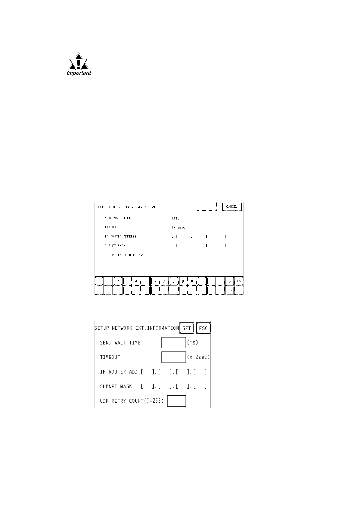
SET UP NETWORK EXT. INFORMATION
<GP-477R/GP-577R/GP-2400/GP-2500/GP-2501/GP-2600/GLC2400/GLC2600 Series>
14
<GP-377R/GP-2300/GLC2300 Series>
GP-PRO/PBIII for Windows Device/PLC Connection Manual
Page 16

Hitachi Industrial Equipment System - Ethernet
• SEND WAIT TIME (0 to 255)
W ait time can be added when a command is transmitted from the GP. Use the
wait time if the traffic on the communications line is heavy . If no wait time is
required, enter “0.”
• TIMEOUT (0 to 65535)
Enter the desired timeout value. If no response is received from the other station
within the specified time, a timeout occurs. If “0” is specified, the default time is
5 seconds with UDP/IP communication.
• IP ROUTER ADDRESS
Enter the IP address of the router (only one). If no router is used, enter “0” in all
fields.
• SUBNET MASK
Enter the subnet mask settings. If no subnet mask is used, enter “0” in all fields.
• UDP RETRY COUNT (0 to 255)
Designates the number of times the GP re-sends a command when there is no
reply from the other port and a timeout occurs. When no reply is received after
the retry setting number is reached, an error message will appear on the GP
screen.
If GP memory is initialized in OFFLINE mode, random values may
be included. Download the GP System Setting data from GP-PRO/
PBIII for Windows.
GP-PRO/PBIII for Windows Device/PLC Connection Manual
15
Page 17
Hitachi Industrial Equipment System - Ethernet
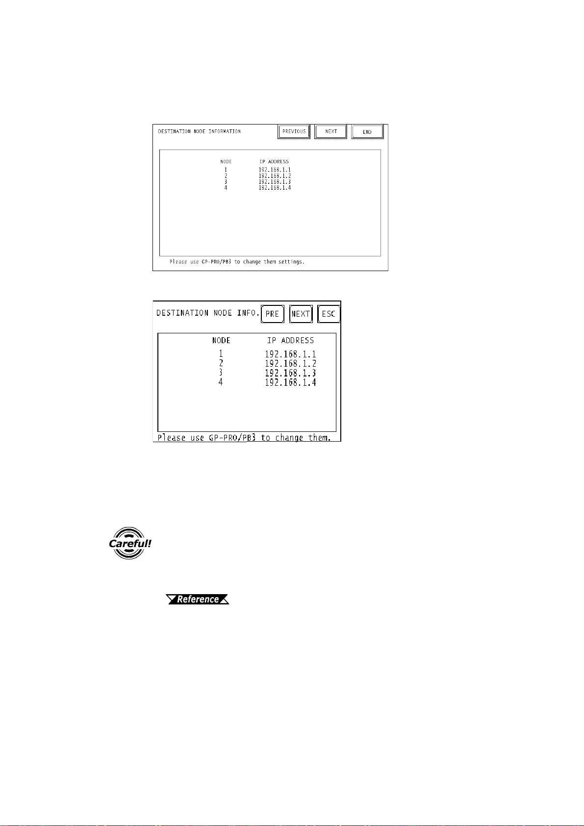
• DESTINATION NODE INFORMATION
<GP-477R/GP-577R/GP-2400/GP-2500/GP-2501/GP-2600/GLC2400/GLC2600 Series>
<GP-377R/GP-2300/GLC2300 Series>
• DESTINATION NODE INFORMATION
PLC Destination Node Number and IP Address are displayed here. Press
[NEXT] button to see the next page.
The DESTINA TION NODE INFORMATION cannot be set or changed
from OFFLINE mode. Set or change these values from GP-PRO/
PBIII for Windows [GP SYSTEM SETTINGS]-> [MODE SETTINGS] > [NETWORK INFORMATION SETTINGS].
This manual, 7.7.3 Environment Setup GP-PRO/PBIII
for Windows Settings
16
GP-PRO/PBIII for Windows Device/PLC Connection Manual
Page 18
Hitachi Industrial Equipment System - Ethernet
y
GP-PRO/PBIII for Windows settings
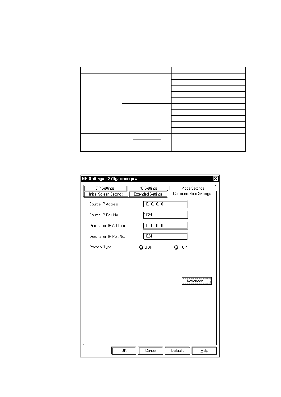
The following items can be entered from GP-PRO/PBIII for Windows [GP SYSTEM
SETTINGS] -> [MODE SETTING] area.
Menu Sub Menu Item
Communication Settings
Advanced Communication
Settings
Mode Settings
Network… D estination Node Information
Source IP Address
Source IP Port No.
Destination IP Address
Destination IP Port No.
Protocol Type
Send Wait Time
Time Out
IP Router Address
Subnet Mask
UDP Retry Count
S
stem Start Address
Read Area Size
COMMUNICA TION SETTINGS
GP-PRO/PBIII for Windows Device/PLC Connection Manual
17
Page 19
Hitachi Industrial Equipment System - Ethernet
• Source IP Address (0 to 255)
Enter the IP address for the GP at your station. T o do this, separate the 32 bits
of the IP address into four segments of eight bits each, separate those segments
with a dot and then enter them as decimal numbers.
• Source IP Port No. (1024 to 65535)
Enter the GP’s Port No. from 1024 to 65535.
• Destination IP Address (0 to 255)
This setting cannot be used. Set the Destination IP Address from [Network
Information Setting] in [Mode Setting] tab.
• Destination IP Port No. (1024 to 65535)
Enter the PLC’s IP Port No. from 1024 to 65535. Enter the same value as the
PLC’s Logic Port No.. When connecting a single GP unit to multiple PLC units,
set all PLC units’ Port No. to the same value.
• Protocol Type
Select UDP/IP or TCP/IP Communication. When the power is turned ON/
OFF asynchronously , we recommend UDP/IP Communication.
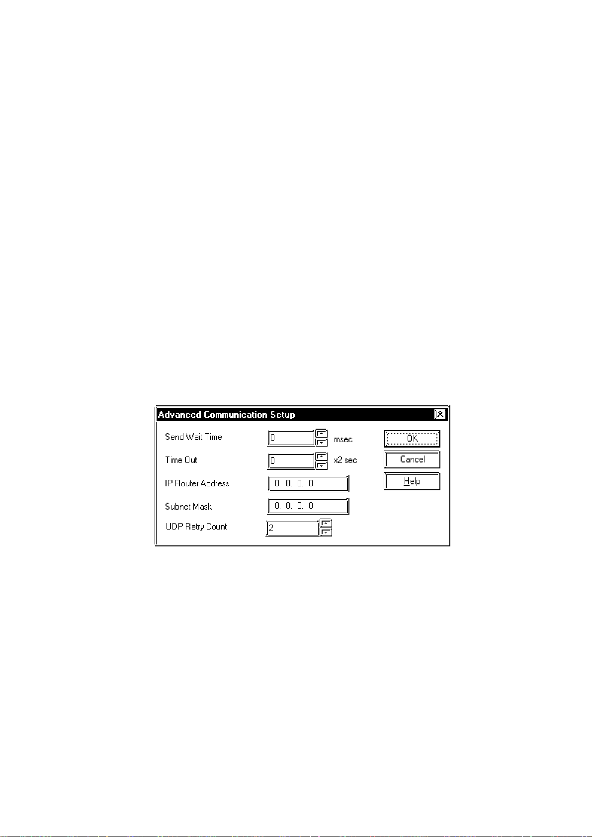
•ADVANCED COMMUNICA TION SETUP
• Send Wait T ime (0 to 255)
W ait time can be added when a command is transmitted from the GP. Use the
wait time if the traffic on the communications line is heavy . If no wait time is
required, enter “0.”
• Time Out (0 to 65535)
18
Enter the desired timeout value. If no response is received from the other station
within the specified time, a timeout occurs. If “0” is specified, the default time is
5 seconds with UDP/IP communication.
• IP Router Address
Enter the IP address of the router (only one). If no router is used, enter “0” in all
fields.
GP-PRO/PBIII for Windows Device/PLC Connection Manual
Page 20
Hitachi Industrial Equipment System - Ethernet
• Subnet Mask
Enter the subnet mask settings. If no subnet mask is used, enter “0” in all fields.
• UDP Retry Count (0 to 255)
Designates the number of times the GP re-sends a command when there is no
reply from the other port and a timeout occurs. When no reply is received after
the retry setting number is reached, an error message will appear on the GP
screen.
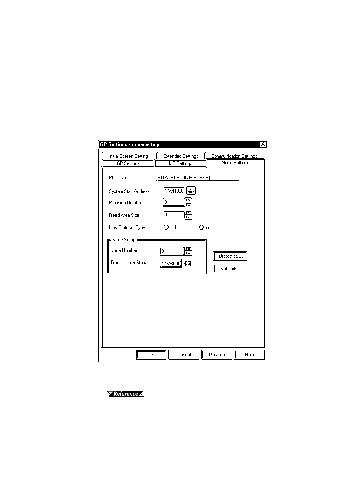
MODE SETTINGS
• System Start Address
The System Start Address is assigned to the PLC node designated here.
For setting, refer to 8.7.2 Supported Devices
GP-PRO/PBIII for Windows Device/PLC Connection Manual
19
Page 21
Hitachi Industrial Equipment System - Ethernet
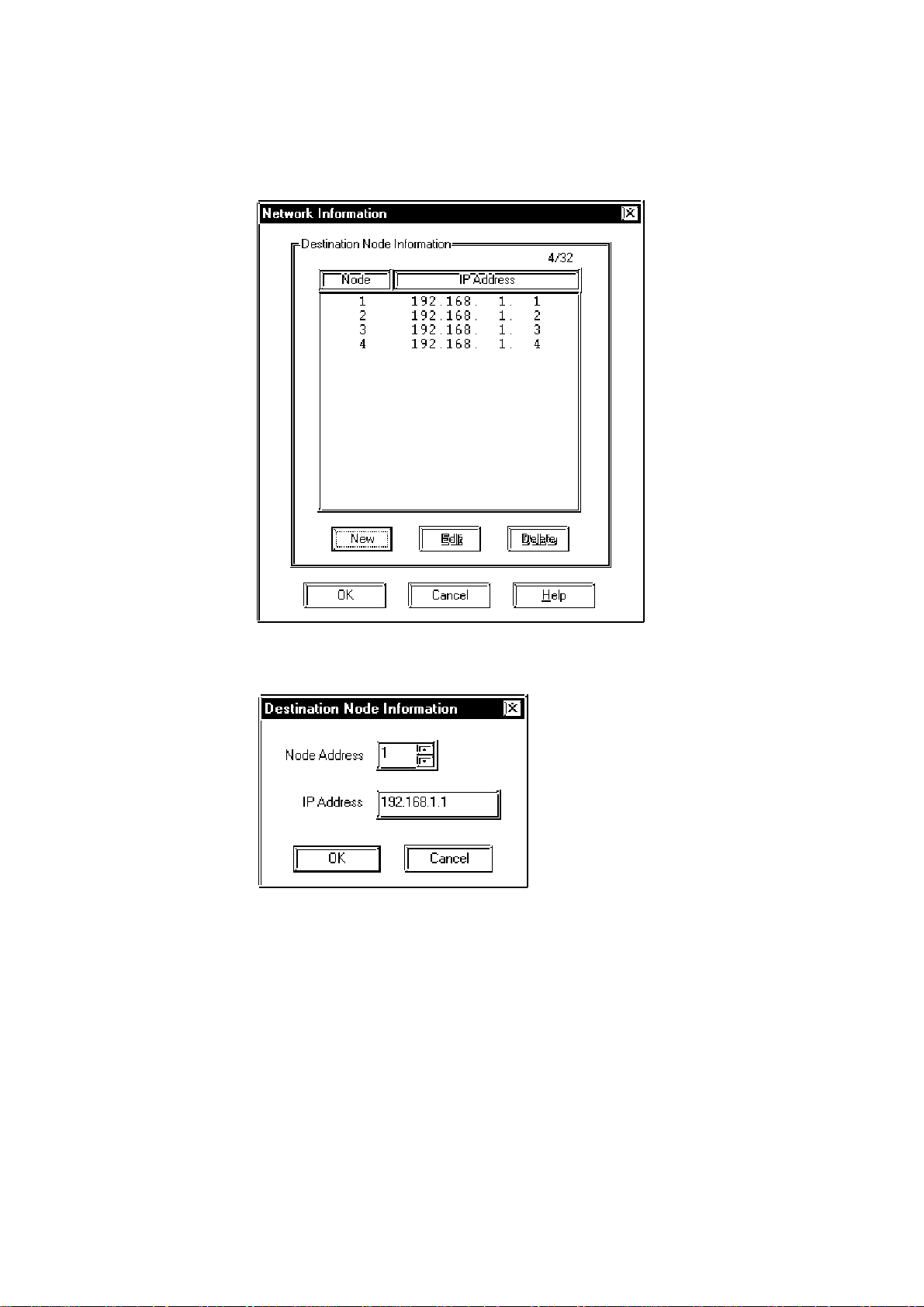
• NETWORK INFORMATION SETTINGS
Click the [Network...] button from[GP System Setting]-[Mode Setting] tab,
and the Network Information window will appear .
Set and editDestination Node Information here.
New Destination Node Information is entered using the following window .
• Destination Node Information
Enter the destination PLC Node number. Click [New] or [Edit] button from
Network Information window or double click the row you want to edit to display the Destination Node Information window .
The Maximum number of Nodes is 32. When the setting Node number is over
32 units, an error “Setting Node number is over 32 units. Cannot set any more.”
appears. When entering the same Node number as the number you have already registered, the error message “The same Node number has already registered.” appears.
20
The Destination Node IP Address needs to be set to the same address as the
target PLC or the junction (intermediate) PLC’ s IP address.
GP-PRO/PBIII for Windows Device/PLC Connection Manual
Page 22
g
g
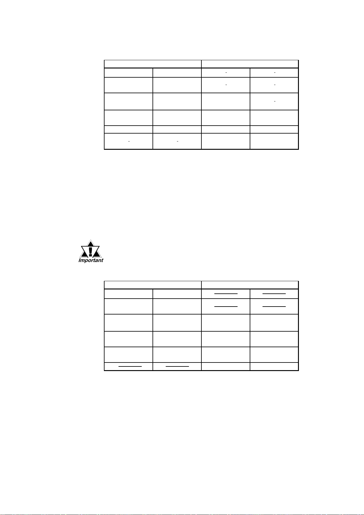
PLC SETTINGS
HIDAC H Series
Hitachi Industrial Equipment System - Ethernet
GP Settin
Source IP Address
Source Node
Address
Destination IP
Address
Destination IP Port
No.
Protocol type UDP/TCP Service Assortment UDP/IP, TCP/IP
s PLC Settings
GP IP Address
GP Port No.
Target PLC IP
Address
3004 to 3007 Logic Port No. GP Node Address
*1
*2
*1
Task Code Port Time
IP Address
Out Value
20 sec. or longer
*1 Contact your network administrator about what setting values to use.
*2 PLC unit’s default Port number is 9600. Be sure to use the same number as
the GP setting.
When using the GP2000 Series unit’s internal ethernet port, be sure the [Logic
Port No.] value is different fron the 2-Way Driver port number values. Check
the 2-Way driver's port number setting via the following menu:
From the GP OFFLINE mode's Main menu [INITIALIZE] -> [SETUP OPERATION SURROUNDINGS] -> [EXTENDED SETTINGS] -> [SETUP ETHERNET
INFORMATION].
The default value is 8000. The 2-Way driver uses this por t and the following
nine ports for a total of 10 (8000 ~ 8009).
• Be sure not to set a duplicate Node Address in the same Network
Address group.
W eb Controller
GP Settin
Source IP Address
Source Node
Address
Destination IP
Address
Destination IP Port
No.
Protocol type TCP/IP, UDP
*1 Contact your network administrator about what setting values to use.
*2 The Port Number setting range is from 1024 to 65535.
*3 When using the GP2000 Series unit’s internal ethernet port, be sure the [Logic
Port Number] value is different fron the 2-Way Driver port number values.
Check the 2-Way driver's port number setting via the following menu:
s PLC Settings
GP IP Address
GP Port No.
Target PLC IP
Address
3004 to 3007
*1
1* *2 *3
*1
1* 2*
Auto IP Address
Task Code Port
Port No. (1 to 4)
Task Code Port
Protocol Type
Mode Switch 0
PLC IP Address
3004 to 3007
TCP/IP, UDP
*1 *2
*1
From the GP OFFLINE mode's Main menu [INITIALIZE] -> [SETUP OPERATION SURROUNDINGS] -> [EXTENDED SETTINGS] -> [SETUP ETHERNET
INFORMATION].
The default value is 8000. The 2-Way driver uses this por t and the following
nine ports for a total of 10 (8000 ~ 8009).
GP-PRO/PBIII for Windows Device/PLC Connection Manual
21
Page 23
Hitachi Industrial Equipment System - Ethernet
7.8.4 Error Codes
For information about GP Ethernet Specific Error Codes,
refer to the “Protocol Stack Error Codes”.
The PLC error codes are displayed by the “ Host Communication Error (02:**)”,
and are indicated in the left lower corner of the GP screen. (** indicates the PLC
error codes)
HIDIC H Series
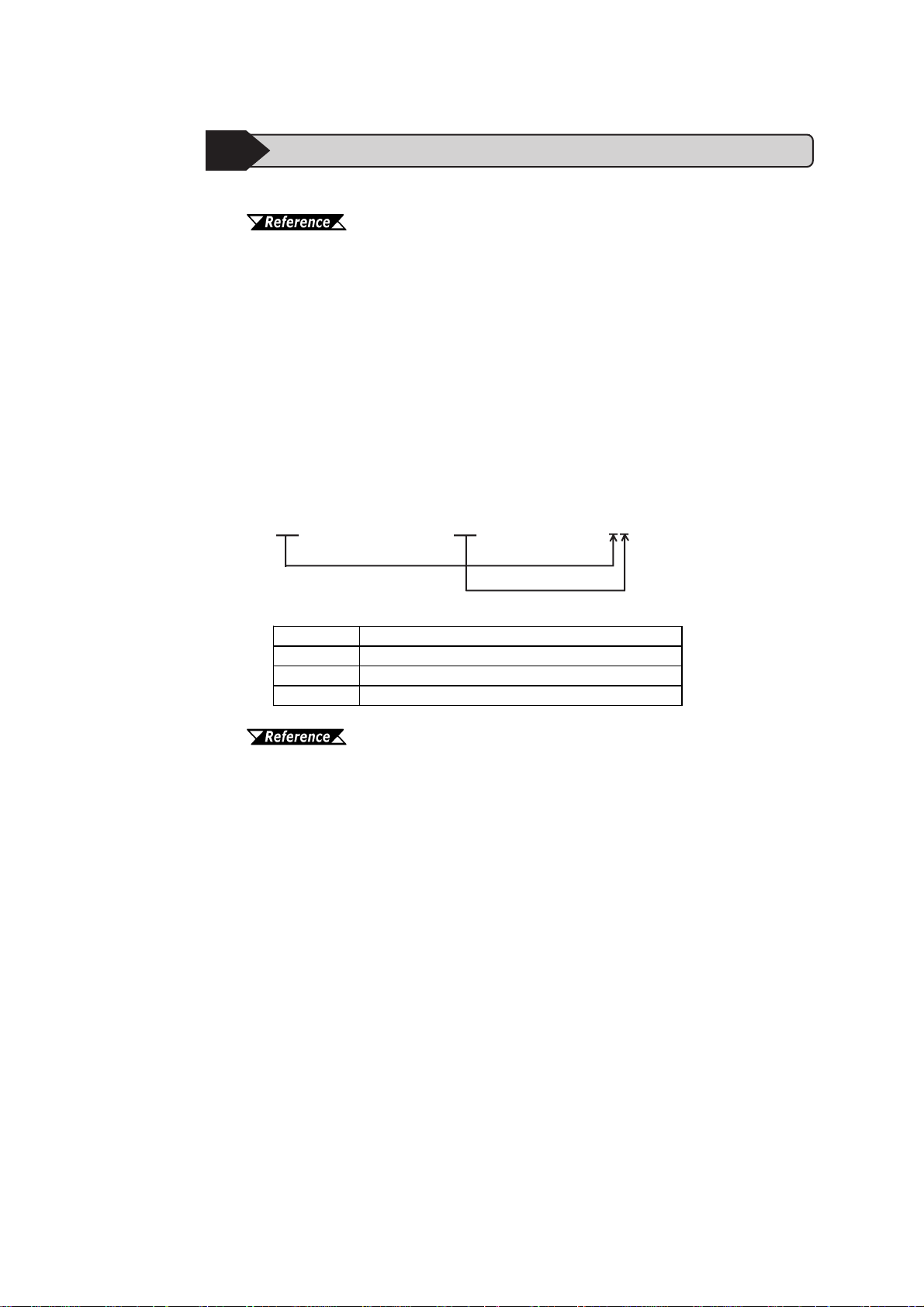
The PLC error codes are sent as separated 2 byte codes. The GP/GLC units use
a 1 byte code to display an error number .
Ex.) PLC Reply Command PLC Return Code GP Display Error
01 07 17
Error Code Conten ts
16 Designated Device does no exist .
17 Designated device address is out of range.
80 Unable to access the designated link unit's PLC.
For information about error codes, refer to Hitachi Industrial Equipment System User Manual for HIDIC H Series.
22
GP-PRO/PBIII for Windows Device/PLC Connection Manual
Page 24
7.9 Protocol Stack Error Codes
Protocol Stack Error Codes are displayed on the GP as follows.
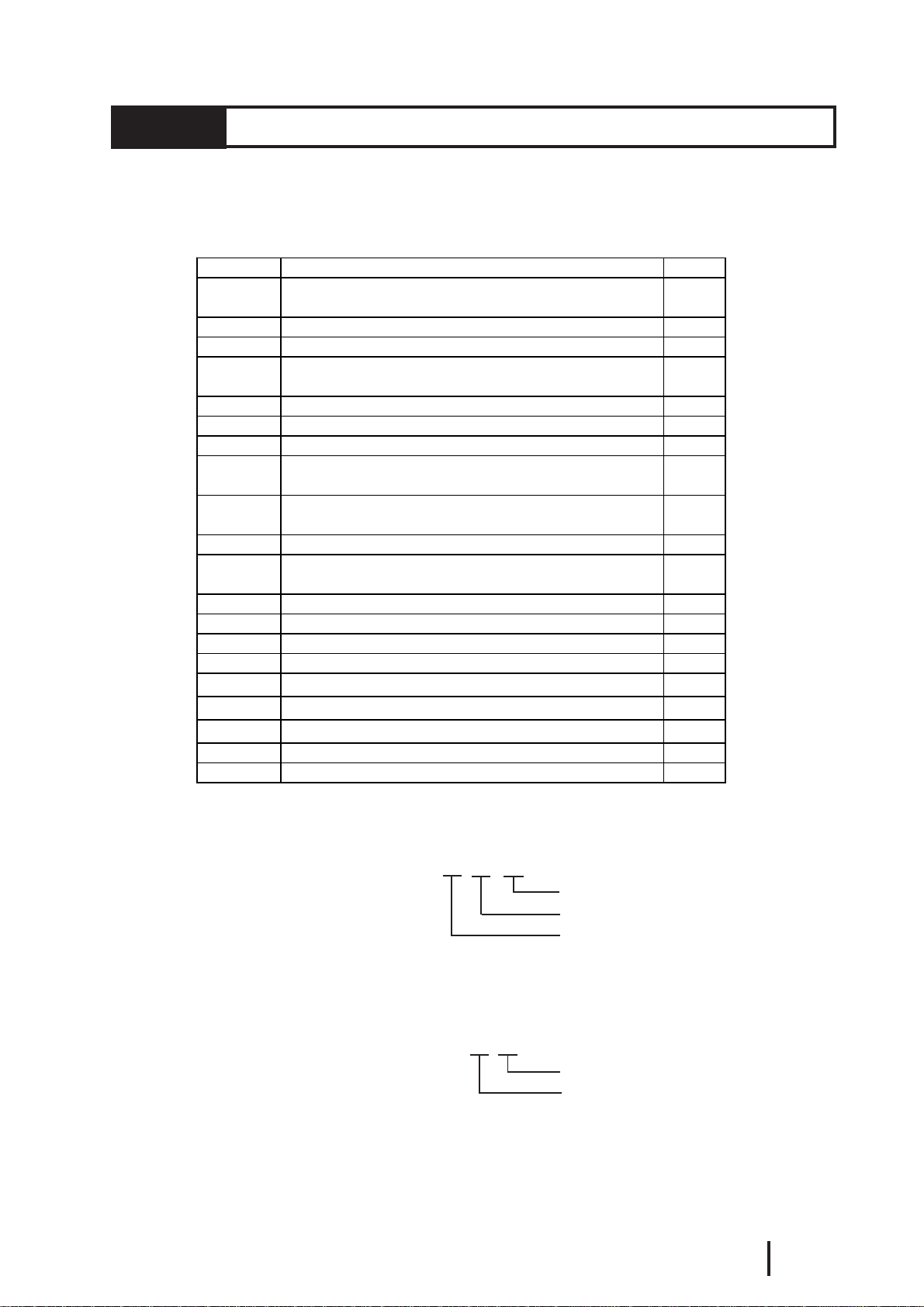
Host communication error (02:FE:**)
** represents one of the following error codes, from 00 to F0.
Error Code Des c ription Note s
00
05 Initialization has fa iled.
06 Cancelling of communications has failed.
07
08 Your station's port number is incorrect
09 The destination stati on's port number is inc orrect.
0A The IP address of the other station is incorrectl.
0B
0C
0D Protocol stack has refused connection establishment.
0E
0F The connection has been shut down.
10 All connections are busy. No connection is available.
13 Your station was aborted by a different station.
30 There was no re ply from the pro tocol stack.
32 There was no re ply from the other station.
40 No network infofmation exists for the designated node.
41 I/O memory type of the random read-out response data is incorrect.
42 Network information does not exist.
F0 Undefined error.
There is a setup error related to the IP address of your station at
initiali z ation.
An attempt was made to establish a connection before
initialization was successfully completed.
The same port number is already being used by UD P for
establishing the connection.
The same port number is already being used by T CP for
establishing the connection.
Protocol stack has returned the unsuccessful establishment of
a connection.
Protocol Stack Error Codes
*1 *2
*1
*1
*1 When using an OMRON Corporation CS1/CJ/CJ1M Series unit, the error code will
appear on the GP screen as shown below . Also, behind the Ethernet error code will
appear the designated Network and Node addresses.
Host Communication Error (02:FE:**:###:###)
*2 When using a Hitachi Industrial Equipment Corporation’ s HIDIC H Series or a
Schneider Corporation MODBUS TCP unit, the error code will appear on the GP
screen as shown below . Also, behind the Ethernet error code will appear the
designated Node address.
Host Communication Error (02:FE:**:###:###)
GP-PRO/PBIII for Windows Device/PLC Connection Manual
Node Address (Decimal)
Network Address (Decimal)
Ethernet Error Code (Hex)
Node Address (Decimal)
Ethernet Error Code (Hex)
1
 Loading...