

Page 1
Flat Panel Display
FP-790T
User Manual
Digital Electronics Corporation
Page 2

FP-790T User Manual 1
1) It is forbidden to copy the contents of this manual, in whole or in part, except for the
user's personal use, without the express permission of the Digital Electronics Corporation
of Japan.
2) The information provided in this manual is subject to change without notice.
3) This manual has been written with care and attention to detail; however, should you find
any errors or omissions, please contact the Digital Electronics Corporation and inform
them of your findings.
4) Please be aware that the Digital Electronics Corporation is not responsible for any damages resulting from the use of our products, regardless of article 3 above.
<Note>
Thank you for purchasing Digital's TFT type color display panel, the 'FP-790T'(hereafter referred
to as "the FP").
The FP is a TFT type color liquid crystal display monitor for Windows compatible personal
computers (VGA, XGA and SVGA modes).
Please read this manual completely to insure the correct use and complete understanding of the
FP's functions.
The FP's analog interface is designed to comply with VESA standards. Please be aware that this
unit may not be able to be connected with devices using nonstandard VGA interfaces. For
further information, please refer to this chapter's "PC Connection Notes" section.
Preface
All Company/Manufacturer names used in this manual are the registered trademarks of their
respective companies.
© Copyright 2001 Digital Electronics Corporation
Page 3
FP-790T User Manual2
• To avoid the possiblity of an electric shock, be sure to connect the power
cord to the FP before connecting it to the main power supply.
• A fire or electrical shock may occur if voltages used with the FP are beyond
the specified range. Be sure to use only the specified voltage.
• Before opening the FP's protective cover, be sure to turn the units power
OFF. This is because the FP's internal parts carry high voltages.
• To avoid fires or electrical hazards, do not modify the FP in any way.
• Do not create touch panel switches that are used to either control or to
ensure the safety of equipment and personnel. Mechanical switches, such
as an emergency stop switch, a deadman (two-handed) start switch, etc.,
must be installed and operated via a separate control system.
• Do not create touch panel switches which could possibly endanger the safety
of humans and equipment. This is due to the possibility of a malfunction in
the FP or its cable(s), causing the output of a signal that could result in a
major accident. All of a system’s major, safety-related switches should be
designed to be operated separately from the FP.
This section describes the safety precautions necessary for the correct use of the FP.
Please keep this manual close at hand and refer to it when necessary.
Safety Icons
The following symbols are used throughout this manual to ensure the safe use of the
FP. Please be sure to follow all instructions given since they explain important safety
points.
Essential Safety Precautions
This mark warns of a situation that could cause
either serious or fatal injury if the instruction is
ignored and/or the unit is used incorrectly.
This mark warns of a situation that could cause
either personal injury or property damage if the
instruction is ignored and/or the unit is used
incorrectly.
Warning
Cautions
WARNINGS
Page 4

FP-790T User Manual 3
WARNINGS
• After the FP's backlight burns out, unlike the FP's "Standby Mode", the touch
panel is still active. If the operator fails to notice that the backlight is burned
out and touches the panel, a potentially dangerous machine operation
mistake can occur.
If your FP's backlight suddenly turns OFF, use the following steps to
determine if the backlight is actually burned out.
1)If your FP is not set to "Standby Mode" and the screen has gone blank,
your backlight is burned out.
2)Or , if your FP is set to Standby Mode, but touching the screen does not
cause the display to reappear, your backlight is burned out.
• If metal particles, water or other types of liquids contact any of the FP's
internal parts, immediately turn the units power OFF, unplug the power cord,
and contact either your FP distributor or the Digital Electronics Corporation.
• Read and understand Chapter 3 "Installation and Wiring" thoroughly in order
to select an appropriate installation location for the FP.
• Before either plugging in or unplugging a board or interface connector, be
sure to turn the FP's power OFF.
• To prevent a possible explosion, do not install the FP in areas containing
flammable gases.
• The FP is not appropriate for use with aircraft control devices, aerospace
equipment, central trunk data transmission (communication) devices, nuclear
power control devices, or medical life support equipment, due to these
devices inherent requirements of extremely high levels of safety and
reliability.
• When using the FP with transportation vehicles (trains, cars and ships),
disaster and crime prevention devices, various types of safety equipment,
non-life support related medical devices, etc. redundant and/or failsafe
system designs should be used to ensure the proper degree of reliability
and safety.
Page 5
FP-790T User Manual4
About the FP's Display Panel
• The FP's currently displayed data, its voltage and brightness setting each affect the intensity
of Contouring. (i.e, when some parts of the screen are brighter than others, creating a
wavelike pattern)
• There are minute grid-points (dark and light) on the Display Panel's surface. This is part of
the FP's design and not a defect.
• Shadows may appear at the top of the LCD. This is normal for an LCD display .
• Sometimes the display area may look as if the display colors have changed. This is a
common attribute of LCD's and is not a defect.
• Displaying a single image for long periods can cause an afterimage to remain when the
display is changed to another screen. To prevent this, periodically turn the FP OFF and
then ON again to remove this afterimage.
• Do not push on the FP’s screen too strongly , with either your finger or with a
hard object. Excessive pressure can scratch, crack or damage the screen.
• Do not use a pointed object, such as a mechanical pencil or screw-driver, to
press any of the touch panel’s switches, since they can damage the display.
• If the screen becomes dirty or smudged, moisten a soft cloth with diluted
neutral detergent, wring the cloth well, and wipe the display. Do not use thinner or organic solvents.
• Avoid exposing the FP to, or operating the FP in direct sunlight, high temperatures and humidity , and in areas where excessive dust and vibration will
occur.
• Avoid using the FP in areas where sudden, extreme changes in temperature
can occur. This may cause con-densation to form inside the unit, possibly
leading to an accident.
• To prevent the FP from overheating, be sure its air circulation vents are clear
and clean, and keep the unit’s operation area well-ventilated.
• Avoid operating or storing the FP near chemicals, or where chemicals can
come into contact with the unit.
CAUTIONS
Page 6

FP-790T User Manual 5
Table of Contents
Preface ...................................................................................................................................... 1
Essential Safety Precautions ............................................................................................................ 2
Table of Contents .............................................................................................................................. 5
CE Marking Notes ............................................................................................................................ 7
PC Connection Notes ........................................................................................................................ 7
FP-790T Features.............................................................................................................................. 8
Package Contents .............................................................................................................................. 9
Symbol Information........................................................................................................................ 10
Chapter 1—Introduction
1-1 Connecting the FP to a PC .....................................................................................................1-1
1-2 Optional Equipment ...............................................................................................................1-3
Chapter 2—Specifications
2-1 General Specifications ............................................................................................................2-1
2-1-1 Electrical Specifications.................................................................................................2-1
2-1-2 Structural Specifications ................................................................................................ 2-1
2-1-3 Environment Specifications ...........................................................................................2-2
2-1-4 Touch Panel Specifications ............................................................................................2-2
2-1-5 External Interface Specifications ................................................................................... 2-3
2-2 Functional Specifications .......................................................................................................2-3
2-2-1 Display Specifications....................................................................................................2-3
2-3 Interface Specifications ..........................................................................................................2-4
2-3-1 Analog RGB Interface....................................................................................................2-4
2-3-2 RS-232C Interface .......................................................................................................... 2-5
2-3-3 Mouse Connector ...........................................................................................................2-6
2-3-4 Mouse Type Host Connector..........................................................................................2-6
2-4 Option Cable Pin Diagrams...................................................................................................2-7
2-5 Parts Names and Functions ..................................................................................................2-9
2-6 Dimensions ...........................................................................................................................2-10
2-6-1 FP-790T External Dimensions ..................................................................................... 2-10
2-6-2 Installation Fasteners....................................................................................................2-11
2-6-3 Panel Cut Dimensions .................................................................................................. 2-10
Page 7

FP-790T User Manual6
Chapter 3—Installation and Wiring
3-1 Installation ...............................................................................................................................3-1
3-1-1 Installation Procedures ...................................................................................................3-1
3-2 Wiring ...................................................................................................................................3-4
3-2-1 Power Cable Connection Precautions ............................................................................3-4
3-2-2 FP Power Cable Connection Procedures .......................................................................3-6
3-2-3 FP Power Supply Connection Procedures .....................................................................3-7
3-2-4 FP Grounding Cautions .................................................................................................. 3-7
3-2-5 FP Input/Output Signal Line Cautions ...........................................................................3-7
3-3 Setup of Operation Mode and Positioning of Display......................................................... 3-8
3-3-1 Operation Mode Setup and Adjustment.........................................................................3-8
3-4 Screen Adjustment using OSD ............................................................................................3-10
Chapter 4—Touch Panel Commands
4-1 Command List .........................................................................................................................4-1
4-2 Touch Panel Data Input..........................................................................................................4-3
4-3 Boot-up Initialization..............................................................................................................4-7
Chapter 5—Troubleshooting
5-1 Troubleshooting.......................................................................................................................5-1
5-1-1 Possible Device Problems .............................................................................................. 5-1
5-1-2 No Display......................................................................................................................5-2
5-1-3 The Touch Panel Does Not Function ............................................................................. 5-4
Chapter 6—Maintenance
6-1 Cleaning the FP's Display ......................................................................................................6-1
6-2 Periodic Check-Up ..................................................................................................................6-2
6-3 Changing the Backlight ..........................................................................................................6-3
Page 8
FP-790T User Manual 7
CE Marking Notes
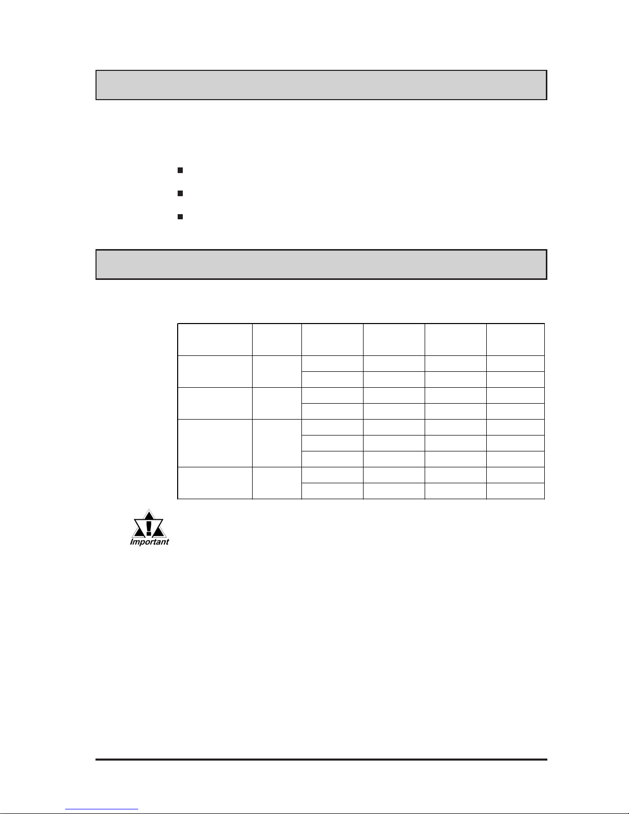
The FP's analog RGB interface offers normal display performance within the
following ranges:
Since some commercially-available video interface equipment also accomodates
tracking ranges in excess of those shown above, they may not offer normal display
performance when used with the PC. Before using a video interface, be sure to
check its specifications.
Also, even if the same type personal computer is used to transfer data to the PC,
the above mentioned problems can also occur when the PC's video board is
replaced.
While the FP('s OS) is starting up, please do not touch the screen's touch panel.
PC Connection Notes
V ESA standard
display m ode
Size
Horizontal
frequency
Vertical
frequency
Dot clock
frequency
Sy nc Logic
V.H
31.469 k Hz 59.992 Hz 25.175 MHz -,-
37.500 k Hz 75.000 Hz 31.500 MHz -,-
37.879 k Hz 60.317 Hz 40.000 MHz +,+
46.875 k Hz 75.000 Hz 49.500 MHz +,+
48.363 k Hz 60.004 Hz 65.000 MHz -,-
56.476 k Hz 70.069 Hz 75.000 MHz +,+
60.023 k Hz 75.029 Hz 78.750 MHz +,+
31.469 k Hz 70.087 Hz 28.322 MHz +,-
37.927 k Hz 85.039 Hz 35.500 MHz +,-
640×480
800×600
1024×768
720×400
VGA
SV GA
XGA
US Text
The FP-790T is a CE marked, EC compliant product.
<Complies with the following Standards>
Safety (EN60950)
EMI (EN55011 class A), EN61000-3-2, EN61000-3-3
EMS (EN61000-6-2)
• The allowable frequency fluctuation range in both the horizontal
and vertical frequencies is +/- 1%. If fluctuations exceed these
ranges, the FP will enter power save mode and the display will go
blank.
• Be sure to turn FP-790T and PC ON at the same time, or before
turning PC ON. If PC is turned ON first, a touch panel and an external mouse will not work.
Page 9

FP-790T User Manual8
• Large-sized, high-quality color LCD
The monitor uses a 14.1 inch TFT type color LCD, and the 260,000 display colors
allow a wide variety of screen designs. The features of this display are easy-toread images and text, wide view angle, high contrast, and fast response.
• FP's large-sized display is XGA mode compatible
The FP is compatible with XGA mode, allowing a large variety of information to
be displayed.
• Display mode is automatically selected (Multi-scan)
The FP's multi-scan feature automatically selects the display mode, according to
the host’ s display mode (VGA, SVGA, XGA or US Text).
• PC data can be displayed on the FP
Since the FP is connected to the host through an analog RGB interface, it can also
be easily connected to a personal computer and used as a display.
For the available display modes, see “PC Connection Notes”
• Rear-mounting type is designed to be built into other equipment
The slim and compact body is designed specifically to be built into machine cabinets
and panels. Since the FP can be easily used with other equipment, it can be used as
a monitor for your PC-based Industrial Automation system. Also, the FP front
panel's installation gasket provides a dust and drip-resistant seal between the FP's
front face and the installation panel. Thus, the FP can be used even in harsh industrial
environments.
• T ouch panel can be operated while PLC data is monitor ed (Standard featur e)
The FP's touch panel is standard equipment and is suitable for monitoring systems
that require touch operations.
FP-790T Features
Page 10
FP-790T User Manual 9
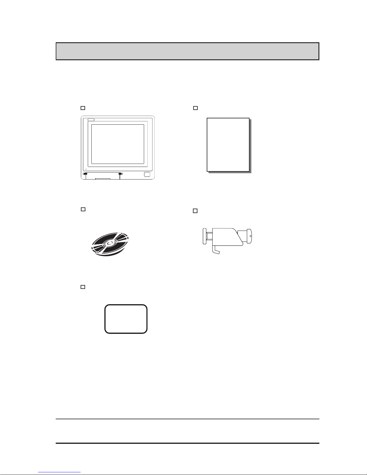
The FP's packing box contains the items listed below. Please check to be sure each is
included and is not damaged.
FP unit (FP790-T21)
CD-ROM *1 Installation brackets (12)
(contains the PDF manuals) <GP070-AT01>
Package Contents
FP-790T Installation Guide
FP-790T
Installation
Guide
These items have all been carefully packed with special attention to product quality.
However, should you find any item(s) damaged or missing, please contact your local
distributor immediately for prompt service.
Installation gasket
<FP790-WP00>
*1 For description and usage of the application programs stored in the floppy disk, see
that disk's English “READ_ME.DOC” file.
Page 11
FP-790T User Manual10
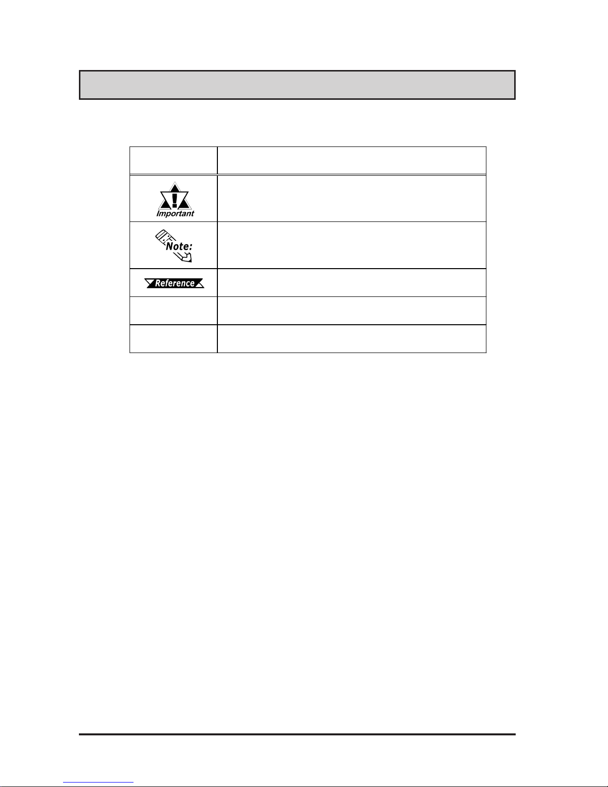
Symbol Meaning
Used to in dicate important information or procedures that must be follo wed for
correct and risk-free software/ device o p eration .
Used to refer to useful or important supplemental inf ormation.
Used to provide useful or important supplemental information.
*1
Used to provide useful or important supplemental information.
1) , 2)
Indicates steps in a procedure. Be sure to perform these steps in the order
given.
Symbol Information
The list below describes the symbols used in this manual.
Page 12
1-1FP-790T User Manual
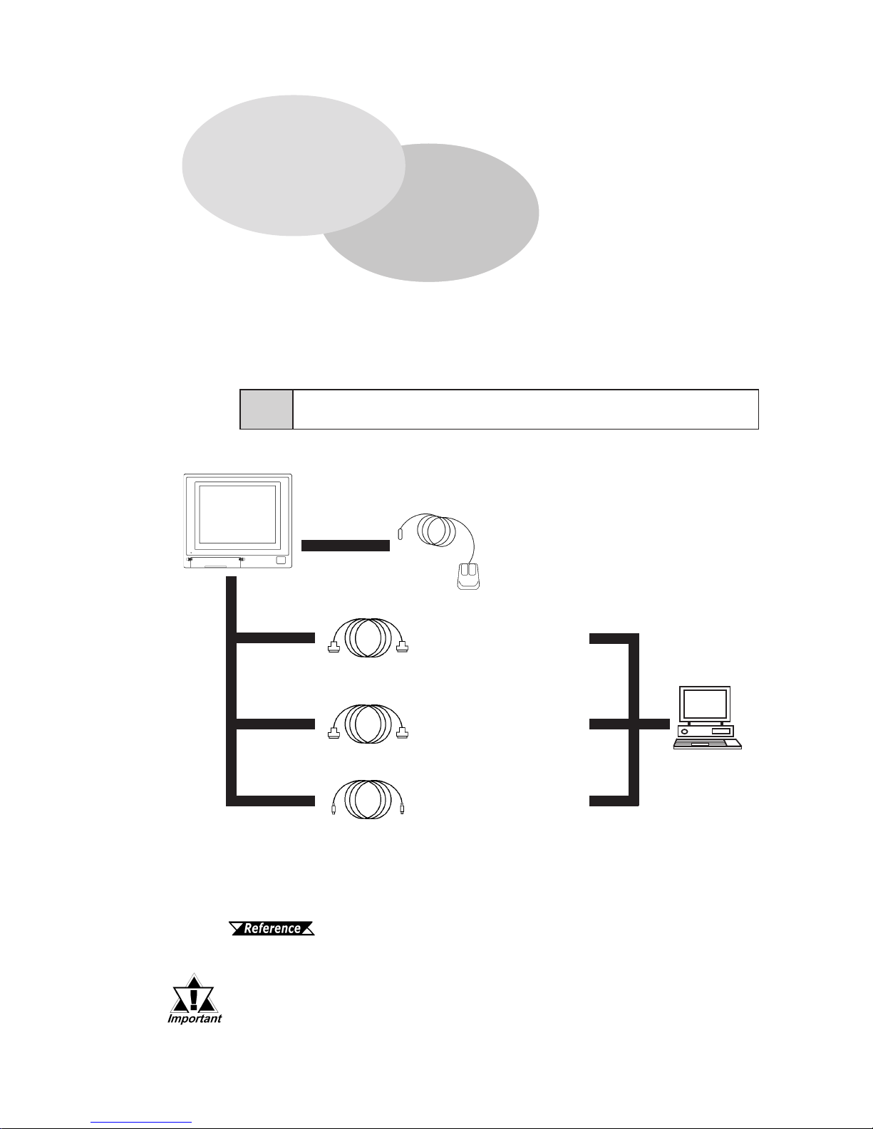
The following diagram illustrates the connection options available between the FP
and a PC.
Chapter 1
Introduction
1. Connecting the FP to a PC
2. Optional Equipment
Microsoft Mouse
(Commercially available type)
Mouse/Keyboard cable
(Keyboard output)
FP-CK01
SIO cable (RS-232C)
FP61V-IS00-O
RGB cable
(Analog RGB input)
FP-CV00, FP-CV01
DOS compatible
personal computer
<OS>
Windows95
Windows98
Windows NT
Windows2000
d
e
f
g
h
i
FP Unit
(FP790-T21)
For a description of each refer ence no. used (h, etc.) refer to the next
page (page 1–2)
c
1-1 Connecting the FP to a PC
The interface connecting a touch panel to a host PC is only RS-232C. It
cannot be communicated with the PS/2 interface.
Page 13
Introduction
1-2 FP-790T User Manual
FP-790 Mouse Emulator for Windows
FP-ME000*
1
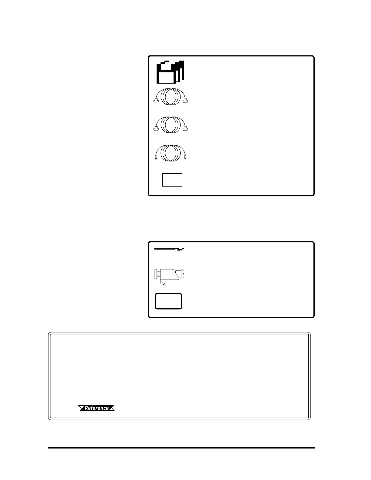
Optional Maintenance Parts
These parts are included in
either the FP or its package as
standard equipment, and are
also optionally available for FP
maintenance.
Optional Parts
(Sold separately)
Backlight (2 lights/set)
FP790T-BL00-MS
Installation Brackets (4 brackets/set)
GP070-AT01
Installtion Gasket
FP790-WP00
Page 1–1 Item Description
FP Interface
c Mouse Connector
d Serial I/F Connector
e Analog RGB I/F Connector
f Host Connector for Mouse
2-5 Names and Functions of FP Parts
Mouse/Keyboard Cable
FP-CK01
Serial I/F Cable
FP61V-IS00-0
Analog RGB Cable
FP-CV00/FP-CV01
Display Protection Sheets (5 sheets/set)
PL-CS500
*1 The FP-ME000 (Mouse Emulator) can only be used with a PC running
the Japanese version of Windows. When an English version of Windows is used, the English version of the U-TP (Gunze Corporation)
software is required. For purchasing information, contact your local
Pro-face distributor.
Personal Align Computer Interface
g Mouse interface
h Serial interface
i Analog RGB interface
Page 14
Introduction
1-3FP-790T User Manual
1-2 Optional Equipment
All optional equipment listed below are products of Digital Electronics Corp.
Model No. Description
SI O cable FP61V-I S 00- O
Serial int er f a ce cable used for t r ans mission of
touch panel data b et w een the FP and various
host s ( P Cs ), and f or the tr ans mission of
commands to the FP. (5 m)
Compatible with PC/AT (D-sub 9-pin female
connector) computers
RGB cable
(2.5m)
FP-CV00
Analog RGB int er f a ce cable used to output
image signals fr om various hos t (PC s) to th e
FP. (2.5 m)
Compatible with ana log RGB int er f a ce (D-s ub
15-pin male connector) .
RGB cable
(5m)
FP-CV01
Analog RGB int er f a ce cable used to output
image signals fr om various hos t (PC s) to th e
FP. (5 m)
Compatible with ana log RGB int er f a ce (D-s ub
15-pin male connector) .
Mouse/
Keyboard
cable
FP-CK01
Used t o connect a mouse bet we en t he h os t and
the FP. (2.5 m)
Compat ible with P S - 2 ( mini DIN 4- pin male
connector) devices.
A keyboard cannot be connected.
Optional
Software
FP-790
Mouse
Emulator
FP-ME000
*
1
Touch panel driver for W indows 9 5, 98, NT,
2000
Backlight FP790T-BL00 Replacement B acklights (2 lights/ s et )
Installation
brackets
GP070-AT01
Used t o s ecure t he FP t o its installation panel.
(4 brackets/set)
Installation
gasket
FP790-WP00
Used to prevent moisture from entering the FP’s
chassis. S ame gaske t as or iginally included
with the FP.
Optional
Parts
Display
protection
sheets
FP77-COVER-5P
Disposable sheets that prot ect the display f rom
dust and d irt . The touch panel can be used
when one of these s heet s is attached. ( 5
sheets/set)
Maintenance
Parts
Interfaces
Ite m Na m e
*1 The FP-ME000 (Mouse Emulator) can only be used with a PC running the Japanese version of
Windows. When an English version of Windows is used, the English version of the U-TP (Gunze
Corporation) software is required. For purchasing information, contact your local Pro-face distributor.
Page 15

1-4 FP-790T User Manual
MEMO
Page 16
FP-790T User Manual 2-1
Chapter 2
Specifications
1. General Specifications 4. Option Cable Pin Diagrams
2. Functional Specifications 5. Names and Descriptions of FP Parts
3. Interface Specifications 6. Flat Panel (FP) Dimensions
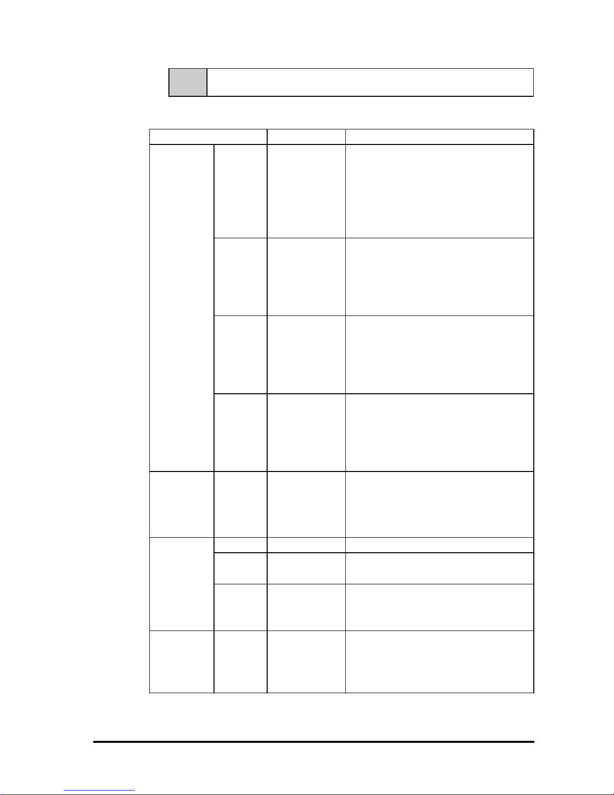
2-1-1 Electrical Specifications
2-1 General Specifications
This chapter includes general specifications, functional specifications, interface
specifications, and part names and dimensions of the FP.
Input Voltage AC 100V t o AC 240V 50 / 60Hz
Rated Voltage AC 85V t o AC 265V 50/60Hz
Allowable Voltage Drop 1 cycle or less
Power C ons um pt ion 65VA or less
In-Rus h C ur r ent
30A (at nor mal t emperat ure ) , 45A (at 40
0
C)
Volta ge Enduranc e
AC 1500V 20mA 1 minute
(bet ween the live wire and gr o unding t er minals)
Isolation Resistance
DC 500V 10MΩ greater
(bet ween the live wire and gr o unding t er minals)
Page 17
FP-790T User Manual
Specifications
2-2
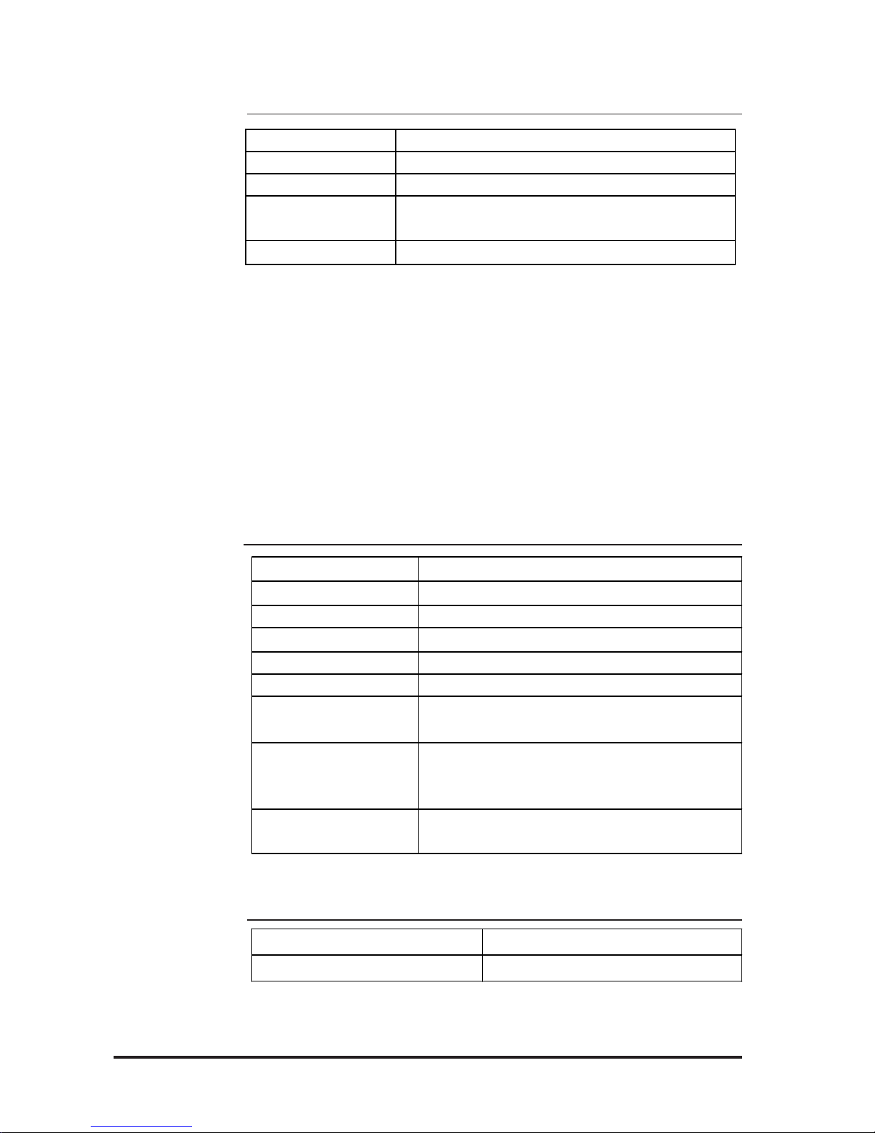
2-1-3 Environmental Specifications
2-1-4 Touch Panel Specifications
Resolution (dot)
1024 X 1024
Method
Resist ive Film (Ana log)
Operating Temperature
0
0
C to 400C
Storage Temperature
- 10
0
C to 600C
Ambient Humidity 30%RH t o 85% RH ( non- condensing)
Dust
0.1mg/m
3
or less (n on- conductiv e levels)
Atmosphere Free of corros ive gases
At mos pher ic E ndur anc e 800hPa t o 11 14hP a ( 2000 met ers or lower)
Vibration Resistance
10Hz to 25Hz
(X, Y, Z directions: 30 minut es each, 19.6m/s
2
)
Noise Immunity
(v ia n ois e s im ula t or )
Noise Volt age : 1500Vp-p
Pulse Dur ation : 50ns , 5 00ns , 1µs
Rise Time : 1 ns
Electrostatic Discharge
Immunity
4k V I E C 6100 0-4- 2
2-1-2 Structual Specifications
*1 The front face of the FP unit, installed in a solid panel, has been tested using conditions
equivalent to the standard shown in the specification. Even though the FP unit’s level of
resistance is equivalent to the standard, oils that should have no effect on the FP can
possibly harm the unit. This can occur in areas where either vaporized oils are present, or
where low viscosity cutting oils are allowed to adhere to the unit for long periods of time. If
the FP’s front face protection sheet becomes peeled off, these conditions can lead to the
ingress of oil into the FP and separate protection measures are suggested. Also, if nonapproved oils ar e present, it may cause deformation or corrosion of the fr ont panel’s plastic
cover. Therefore, prior to installing the FP be sure to confirm the type of conditions that
will be present in the FP’s operating environment.
If the installation gasket is used for a long period of time, or if the unit and its gasket are
removed from the panel, the original level of the protection cannot be guaranteed. To maintain the original protection level, you need to replace the installation gasket regularly.
Grounding 100Ω or less , or your country's applicable st andar d
Cooling Method Natural air circulation
Weight 6.5k g [ 14 . 3lbs .] or les s ( Unit only)
External D ime ns ions
W405mm [15.94in.] x H350mm [13.78in.] x D75mm [2.95in.]
(not including rear pr ojections)
Ratings
*1
Equivalent to IP65f (JEM 1030)
Page 18
FP-790T User Manual
Specifications
2-3
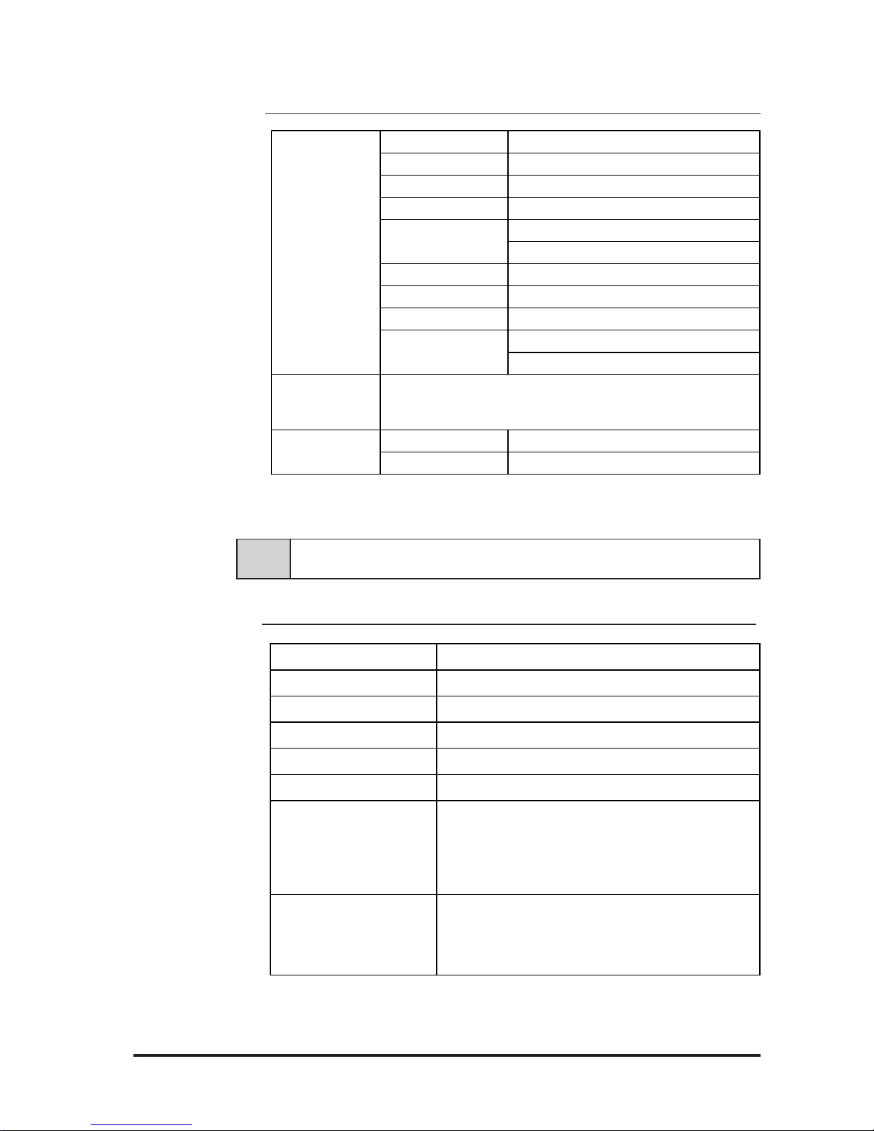
2-2 Functional Specifications
2-2-1 Display Specifications
2-1-5 Display Specifications
Display Media TF T c olor LCD
Display Colors 260,000
Contrast Adjustment Poss ible via adjustment menu
Dot Pitch W0.273mm x H0.2 73mm
Touch P ane l Res olut ion 1024 x 1024
Display Area 285.7mm [11. 25 in.] x 214.3mm [8.44 in. ]
Display Mode
(selected via switch)
640 x 480 ( VGA)
720 x 400 ( US Text)
800 x 600 ( S VGA)
1024 x 768 ( X GA)
Backligh t
CFL
(under continuous 2 4 hour oper ation,
lifespan = 30,000 hours )
Input S ignal A n alog RGB
Image Signal A n alog RGB
Synchronous S ignal TTL Level, negative True or positive true
Scanning Ty pe Non-int erlaced
Clock adjustment: - 128 t o 128
Phase adjus t ment: 64 levels
Contr as t Contr ol via touch panel
Bright ne s s Cont r o l via touch panel
Color Cont r ol via red, gr een, blue set tings
Horiz ontal Display
Vertical Disp lay
Serial I/F
(RS-232C)
(MOUSE I N) PS/2 Interf ace mini DIN 6-pin f e male
(MOUSE OUT) PS/2 I nterf ace mini DIN 4-pin f e male
Mouse I/ F
Analog RGB I/F
(RGB IN)
Posit ionin g control
Displa y Ad justment
Asynchronous Transmission, RS 232C , Data Lengt h: 8 bit s, St op B it :
1, P ar it y: None, Odd or E ven, Transfe r S pee d: 9600bps
Page 19
FP-790T User Manual
Specifications
2-4
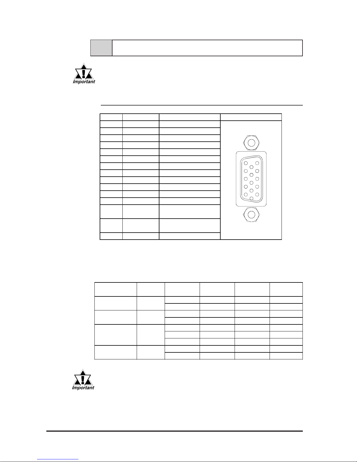
2-3-1 Analog RGB Interface (RGB IN)
2-3 Interface Specifications
Be sure to use Proface's optional cable. If any other cable is used, due to
possible noise interference, Proface cannot guarantee the FP will perform
as specified.
VE SA S tandar d Horiz ont a l Vertic a l Dot C lock S y nc Logic
Display Mode Frequency Frequency Frequency V. H
31.469 k Hz 59.992 Hz 25.175 MHz -,-
37.500 k Hz 75.000 Hz 31.500 MHz -,-
37.879 k Hz 60.317 Hz 40.000 MHz +,+
46.875 k Hz 75.000 Hz 49.500 MHz +,+
48.363 k Hz 60.004 Hz 65.000 MHz -,-
56.476 k Hz 70.069 Hz 75.000 MHz +,+
60.023 k Hz 75.029 Hz 78.750 MHz +,+
31.469 k Hz 70.087 Hz 28.322 MHz +,-
37.927 k Hz 85.039 Hz 35.500 MHz +,-
720×400
VGA
SV GA
XGA
US Text
Size
640×480
800×600
1024×768
Pin N o. Signal N a m e Condition Pin Loca tion
1 ANALOG R R Signal I nput
2 ANALOG G G Signal Input
3 ANALOG B B Signal I npu t
4 NC No Connection
5 GND GND
6 RETURN R R S ignal GND
7 RETURN G G Signal GND
8 RETURN B B Signal GND
9 NC No Connection
10 GND GND
11 NC No Connection
12 NC No Connection
Horizont al S ynchronous
Signal I nput
Vert ical Synchronous
Signal I nput
15 NC No Connection
H. SYNC13
V. SYNC14
The allowable frequency fluctuation range in both the horizontal and
vertical frequencies is +/- 1%. If fluctuations exceed these ranges,
the FP will enter power save mode and the display will go blank.
Recommended Connector: Mini Dsub 15 pin (JST Co.) KEY-15S-2A3F eqivalent
Connector set screw: Inch type (4-40UNC)
Cable: Digital Electronics Corporation RGB cable (FP-CV00,
FP-CV01)
Page 20
FP-790T User Manual
Specifications
2-5
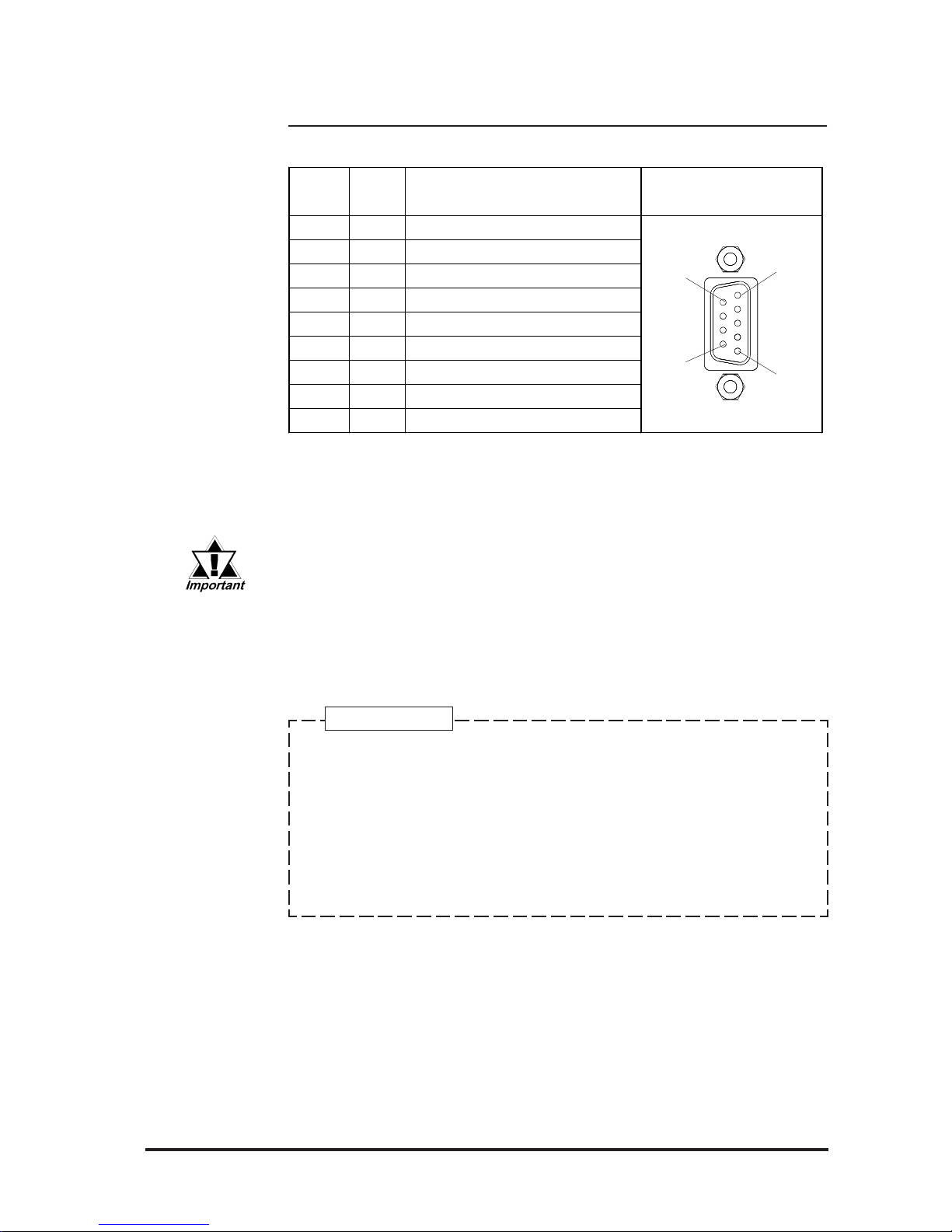
2-3-2 RS232C Interface (COM1/COM2/COM3)
Pin Assignments and Signal Names for Serial Interface Connector
1
5
6
9
Signal Names
Signal names used for the FP's serial interface are designed to match the
pin order used on most PC serial interfaces, so that a straight cable can be
used to connect the two. Therefore, connect each pin's signal to the same
signal name on the PC connector.
For example, pin #2 'RD' should be connected to the 'RD' input terminal
on the FP's connector.
Refer to section "2-4 Option Cable Pin Diagrams" for information about
each signal's direction.
Pin No.
Signal
Name
Condition Pin Loca tion
1 CD Carrier Detect (FP –> Host )
2 RD Receiv e Dat a (FP –> Host)
3 TD Send Dat a ( FP < – Ho s t )
4 DTR Data Terminal Ready ( FP <– Ho st )
5 GND Ground
6 DSR Data Set Rea dy (FP –> Host )
7 RTS Request t o S end ( FP < – Hos t)
8 CTS Clear t o S end ( FP –> H os t )
9 RI Not Us ed
• Since all serial interface signals are the same on the PC side, use a
straight cable to connect the FP to the PC.
• The GND terminal is the signal ground. Be sure to connect the GND
terminal to other unit’s SG (signal ground).
Recommended Connector: Mini Dsub 9-pin (JST Co.) JEY-9P-1A3F eqivalent
Connector set screw: Inch type (4-40UNC)
Cable: Digital Electronics Corporation SIO cable
(FP-61V-IS00-0)
Page 21
FP-790T User Manual
Specifications
2-6
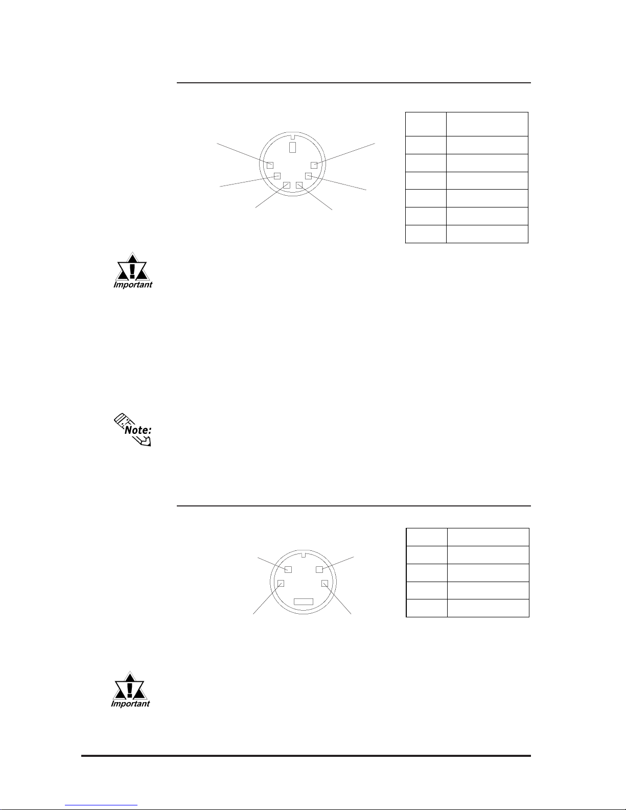
2-3-3 Mouse Connector (MOUSE IN)
Mini DIN 6-pin (Female)
<Manufactured by Hoshi Electronics,Inc.:
TCS7568-43-201 or equivalent>
(Common to front and side)
Pin
No.
Signal name
1
MOUSE DATA
2
NC
3
GND
4
+5V (OUT)
5
MOUSE CLK
6
NC
2-3-4 Mouse Type Host Connector (MOUSE OUT)
Mini DIN 4-pin (Female)
6
4
2
1
3
5
Pin No. Signal name
1
GND
2
+ 5V
3
MOUSE CLK
4
DATA
<Connector Maker: JST, JST/MD-S6100 or equivalent>
21
3
4
• The mouse connection can be used for all equipment conforming to
the PS/2 mouse standards. However, Pro-face cannot guarantee the
FP will operate normally for all types of host and mouse combinations.
This unit was developed using the Microsoft Mouse®. Microsoft's other
mouse products, the "IntelliMouse" and the "3 Button" mouse cannot
be used with this unit.
• When connecting the Mouse, be sure to use the Mouse Type Host
connector (MOUSE OUT) and the Host PC Mouse/Keyboard cable (FPCK01)
• Do not connect this cable when the power to the FP and the host (PC)
are both ON.
• After connecting the mouse, please re-start the Host unit's OS.
• When Windows 95 or Windows NT is used, set the “Control panel Mouse - Motion” feature to the standard pointer speed and hide the
pointer trace.
• If the Host PC Mouse/Keyboard cable (FP-CK01) is not used with the
Mouse Type Host connector (MOUSE OUT), the mouse cannot be
used.
• Do not connect this cable when the power to the FP and the host
(PC) are both ON.
Page 22
FP-790T User Manual
Specifications
2-7
2-4 Option Cable Pin Diagrams
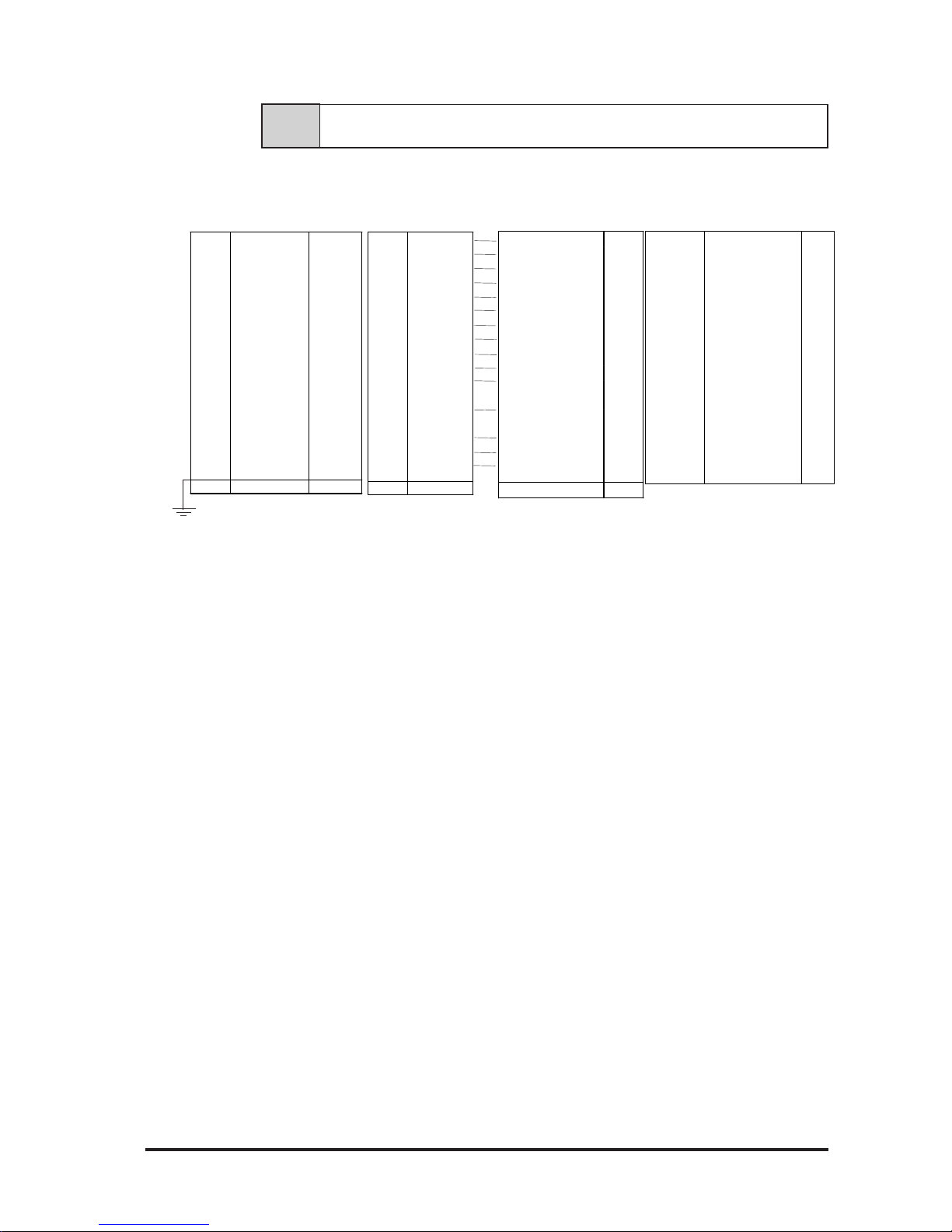
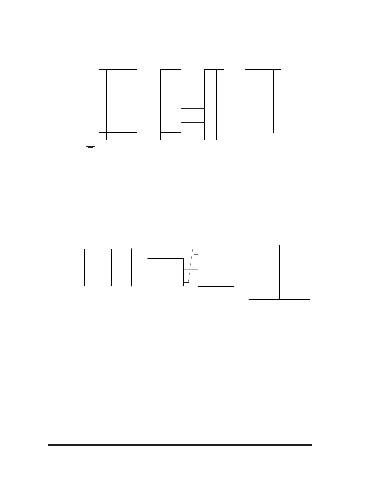
RGB Interface Cable Pin (Optional cable: VGA specification) Assignments
FP Connector PC ConnectorRGB cable
Signal names for the FP's RGB interface are designed to match the same pin
order as the RGB interface on standard PCs. Since this cable is designed to use
the same pin numbers for the FP and the PC, it can be connected in either direction.
Since the PC connector's pitch is designated in “inch” units, the interface cable
and the FP connector's pitch are also designated in “inch” units (4-40UNC).
1 Analog R Input
2 Analog G Input
3 Analog B Input
4 Reserved –
5 Digit a l
ground
–
6 Return R –
7 Return G –
8 Return B –
9 Reserved –
10 Digital
ground
–
11 R eserved –
12 R eserved –
13 H .SYNC Input
14 V.SYNC Input
15 R eserved –
FG FG –
1RED IN
2 G RN IN
3 B L U IN
4NC
5GND
6RED
GND
7GRN
GND
8BLU
GND
9NC
10 GND
11 NC
12 NC
13 HSYN
14 VSYN
15 NC
FG FG
RED VIDEO 1
GRN VIDEO 2
BLU VIDEO 3
NC 4
GROUND 5
GROUND RED
6
GROUND GRN
7
GROUND BLU
8
NC 9
GROUND 10
MONITOR
SENSE(COLOR
)
11
MONITOR
SENSE
(
MONO
)
12
HSYN 13
VSYN 14
NC 15
FG FG
Output RED VIDEO 1
Output GRN VIDEO 2
Output BLU VIDEO 3
–NC4
– GROUND 5
– GROUND RED 6
–
GROUND GRN
7
–
GROUND BLU
8
–NC9
– GROUND 10
–
MONITOR
SENSE
(
COLOR
)
11
– MONITOR
SENSE
(
MONO
)
12
Output HSYN 13
Output VSYN 14
–NC15
Page 23
FP-790T User Manual
Specifications
2-8
CD 1
RD 2
SD 3
DTR 4
GND 5
DSR 6
RS 7
CS 8
RI 9
FG 9
Pin Connections for the SIO Interface Cable (Optional cable: PC/A T specification)
Signal names for the FP's SIO interface are designed to match the same pin order
as the SIO interface on standard PCs. As a result, it can be connected in either direction.
Since the PC connector's pitch is designated in “inch” units, the interface cable
and the FP connector's pitch are also designated in “inch” (4-40UNC) units.
FG
Mouse/Keyboard cable pin numbers
1GND
2+5V
3CLK
4DATA
DATA 1
NC 2
GND 3
+5V 4
CLK 5
NC 6
Input/
Output
DATA 1
-NC2
-GND3
-+5V4
Input/
Output
CLK 5
-NC6
FP Connector
Mouse/Keyboard cable
PC Connector
The signal names of the FP unit interface and the mouse/keyboard cable (FPCK01) conform to those of the personal computer interface. T o prevent accidents
and connector damage, please be aware that the ends of this connector are
different. Connect the 4 pin (white) connector to the FP, and the 6 pin (black)
connector to the PC.
1 CD Output
2 RD Output
3 SD Input
4 DTR Input
5 GND -6 DSR Output
7 RS Input
8 CS Output
9 NC --
FG FG --
Input CD 1
Input RD 2
Output SD 3
Output DTR 4
-- GND 5
Input DSR 6
Output RS 7
Input CS 8
Input RI 9
1 CD
2 RD
3 SD
4 DTR
5 GND
6 DSR
7 RS
8 CS
9 NC
FG FG
PC Connector
FP Connector
SIO cable
1GND 2 +5V 3CLK
Input/
Output
4
DATA Input/
Output
(WHITE) (BLACK)
Page 24
FP-790T User Manual
Specifications
2-9
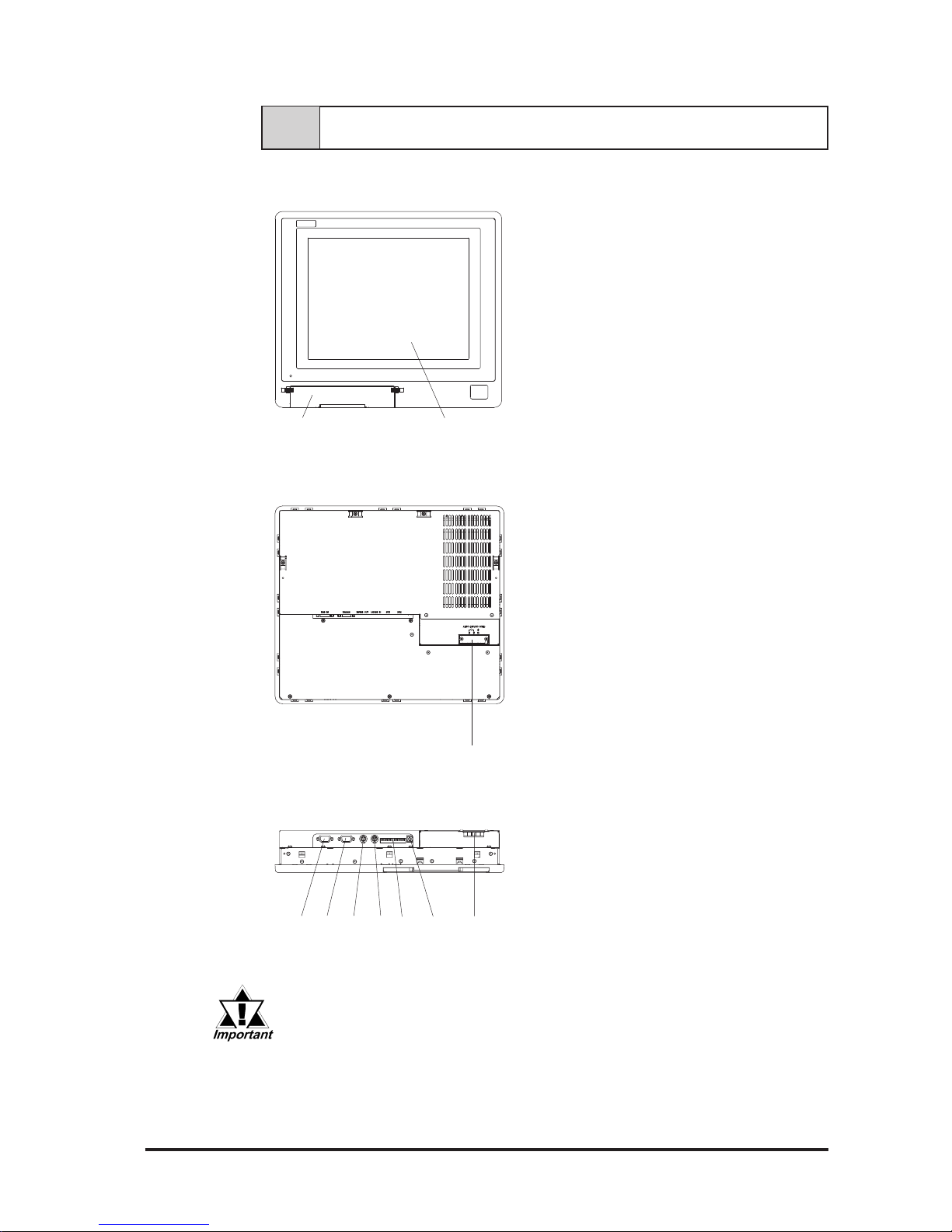
2-5 Parts Names and Functions
A,B
Front View
C
J
Rear View
EFGHI
Bottom View
Be sure that all cables are connected correctly and that the FP is
turned OFF before any cables are disconnected, since either of
these can cause the FP to malfunction.
CD
A: TFT type color LCD
The FP units’ output display. Data
from the host are displayed.
B: Touch panel
Used to switch screens and write data
to the host.
C: Power input terminal block
Used to connect the power supply
cable.
D: Status LED (Under development)
E: Setup switches (DIP switches)
Used to set the FP's operation mode.
F: MOUSE Connector (MOUSE IN)
Used to connect a mouse.
G: MOUSE Host connector (MOUSE
OUT)
Sends mouse output data from the FP.
Connects to the Host’ s PS\2
equivalent Mouse input connector.
H: Serial I/F Connector (RS-2332C)
Serial RS-232C interface. This
connects a serial cable to the FP, and
sends FP touch panel data to the Host,
and Host commands to the FP.
I: Analog RGB I/F connector
Analog RGB interface connector
J: Front Maintenance Cover (unused)
Page 25
FP-790T User Manual
Specifications
2-10
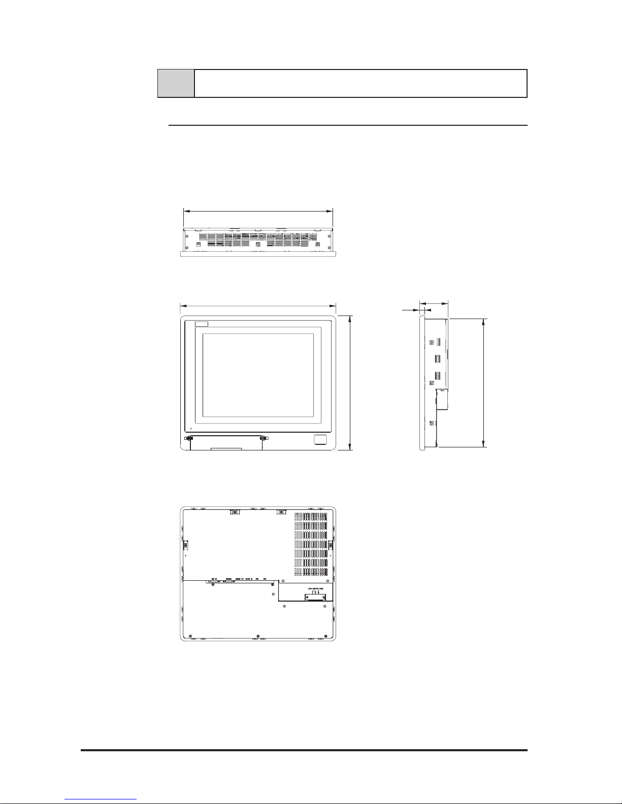
Top View
Front View
405 [15.94]
350 [13.78]
74 [2.91]
13.5 [0.53]
Side View
Rear View
2-6 Dimensions
334 [13.15]
389 [15.31]
2-6-1 FP-790T External Dimensions
Unit: mm [in.] (excluding projections)
Page 26
FP-790T User Manual
Specifications
2-11
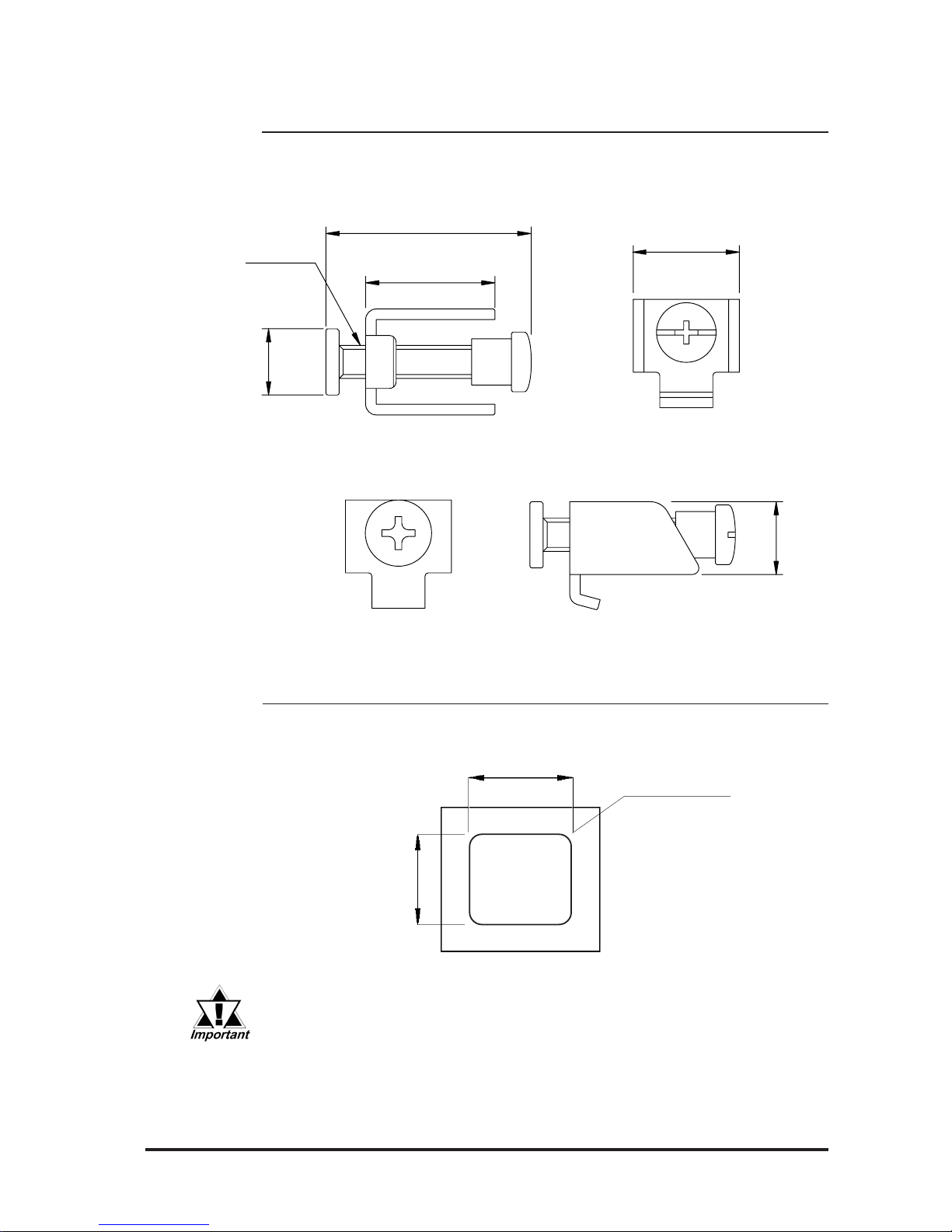
2-6-2 Installation Fasteners
2-6-3 Panel Cut Dimensions
• If the FP's mounting panel is not sufficiently thick or strong, the specified level of moisture-resistance may not be possible.
• If the dimensions of the Panel Cut are larger than those given here,
the panel can warp and distort the FP unit’s display.
Panel
less than 4-R3
Side ViewFront View
Rear ViewTop View
11[0.43]
M5
10 [0.39]
31 [1.22]
19.5 [0.77]
16 [0.63]
Unit: mm [in.] (excluding projections)
Unit: mm [in.] (excluding projections)
390.0 [15.35 ]
+0.5
0
+0.02
0
335.0 [13.19 ]
+0.5
0
+0.02
0
Page 27

FP-790T User Manual2-12
MEMO
Page 28
FP-790T User Manual 3-1
Rear
Face
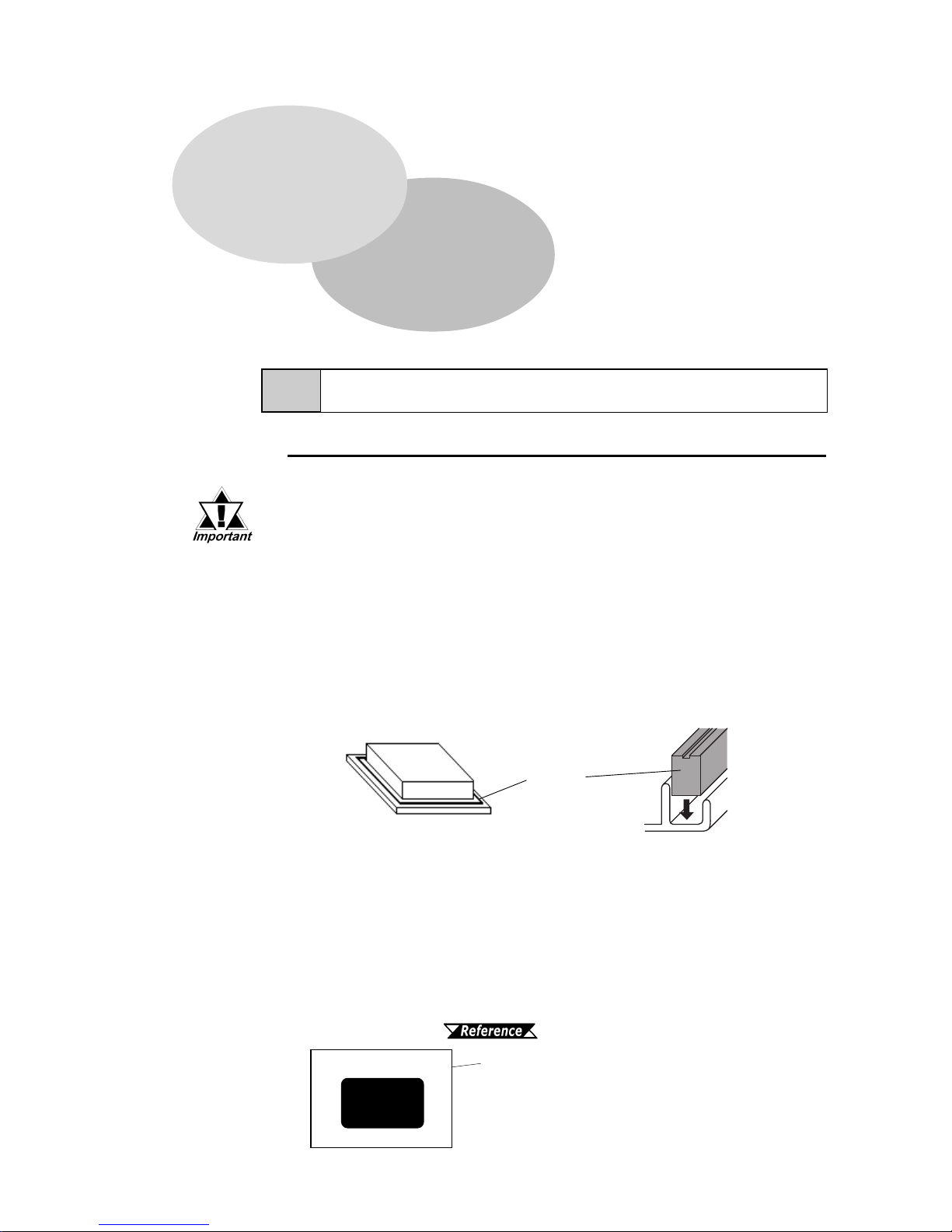
Gasket
3-1 Installation
1. Create a Panel Cut
Using these FP installation dimensions as a guide, create (cut) the correct sized
installation opening. The FP's seal, installation brackets and screws are all required
when installing the FP. 2-6-3 FP Panel Cut Dimensions
Chapter 3
Installation and Wiring
1. Installation
2. Wiring
3. Setup of Operation Mode and Positioning of Display
• Before mounting the FP into a cabinet or panel, check that the
Installation Gasket is attached to the unit.
• A gasket which has been used for a long period of time may
have scratches or dirt on it, and could have lost much of its dust
and drip resistance. Be sure to change the gasket periodically,
or when scratches or dirt become visible.
• The gasket must be inserted correctly into the groove for the
FP’s moisture resistance to be equivalent to IP65f.
• The upper surface of the gasket should protrude approximately
2mm out from the groove. Be sure to check that the gasket is
correctly inserted before installing the FP into a panel.
Panel
Cut
Installation Plate/Panel
3-1-1 Installation Procedures
Install the FP according to the following procedures.
• The gasket is flexible, but not elastic, and may tear if stretched
too far. Do not stretch the gasket around the ribs, only push.
• Be sure the gasket’s seam is not inserted into any of the unit’s
corners, only in the straight sections of the groove. Inserting it
into a corner may lead to its eventually tearing.
Page 29
FP-790T User Manual3-2
Installation and Wiring
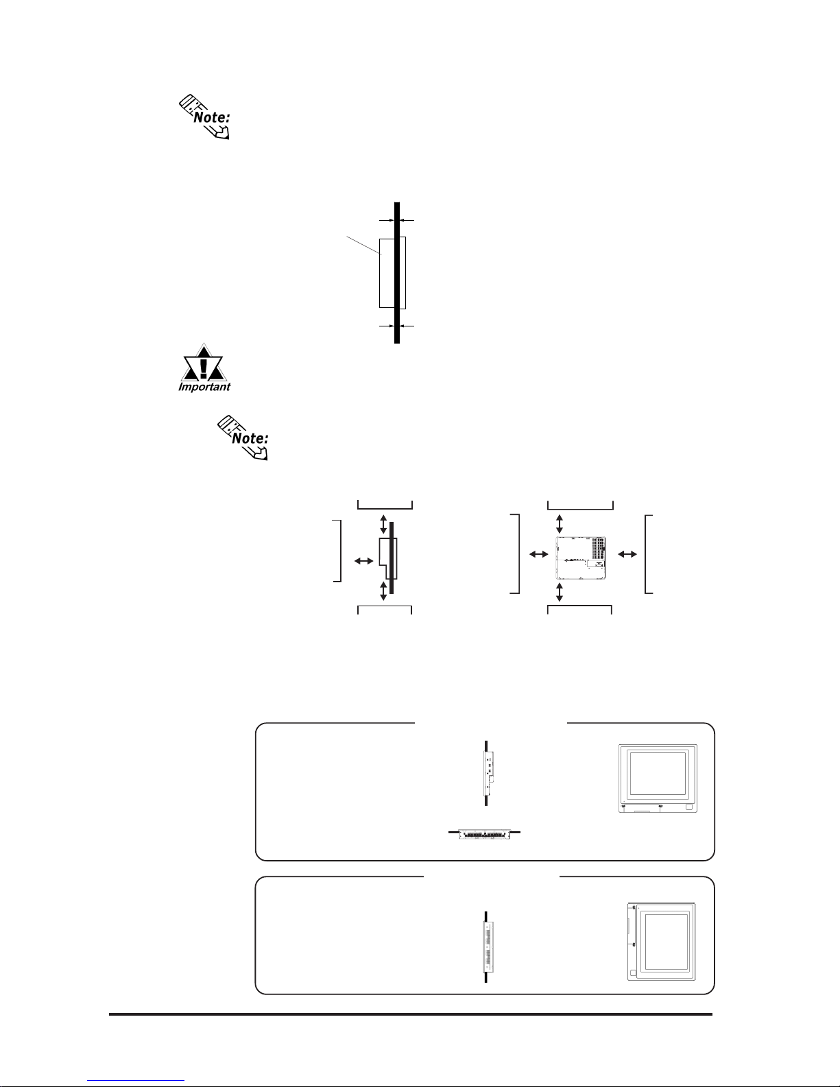
• For easier maintenance and operation, and improved ventilation, be
sure the FP is installed at least 100 mm away from any adjacent
structures or objects.
Front
View
Side
View
(Flat Type)
(Landscape type)
(Portrait Style)
(Looking down at)
• The FP uses natural ventilation through its outer shell for cooling.
When installing the unit horizontally or sideways (portrait style),
use a fan or air conditioning unit to prevent overheating.
Horizontal Installation
Vertical Installation
100mm
100mm
100mm
100mm
100mm 100mm
100mm
Front
View
Side
View
• It is important that the plate/panel surface is flat, clean, and without any
jagged edges.If the panel is thin and may warp, attach a reinforcing plate to
the panel.
• The Plate/Panel thickness should be between 1.6 and 10.0mm.
1.6mm[0.06in.]~ 10mm[0.39in.]
If the plate/panel used is too thin or weak, a satisfactory moistureresistant seal may not be created.
FP
Page 30
FP-790T User Manual 3-3
Installation and Wiring
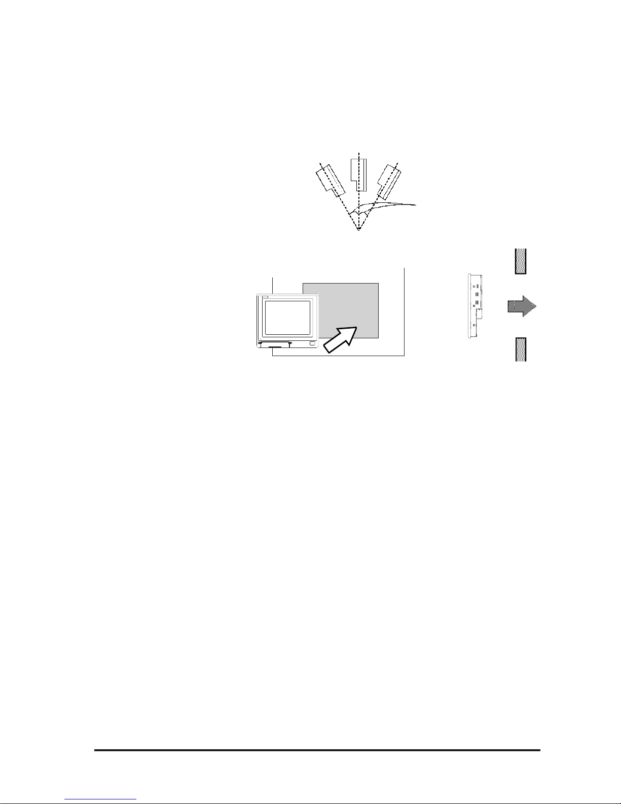
less than 30
o
• Check that heat from surrounding equipment will not cause the FP to overheat.
• Be sure this unit is located as far away as possible from electromagnetic circuits, non-fuse type breakers, and other equipment that can cause arcing.
• When installing the FP in a panel with an angled face, the face should not
incline either backwards or forwards more than 30
o
.
Insert the FP into the panel cut from the front of the panel.
Panel
Side
view
Page 31
FP-790T User Manual3-4
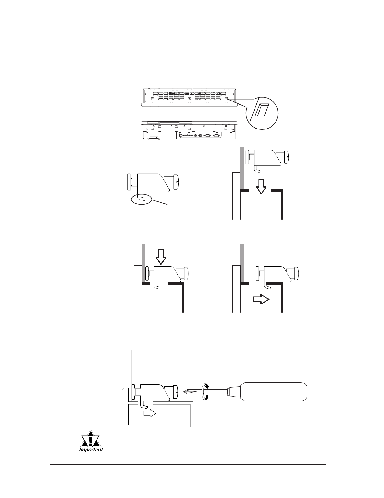
Installation and Wiring
Fastener slot
d
Mounting Bracket
Hook
Panel
Front
Fastener
slot
Rear
e After inserting the hook into the slot, move the bracket backward. Then, use
a screwdriver to tighten the screw and secure the FP in place.
Tighten the installation fastener's screw with a screwdriver. To ensure the FP's
front panel is sufficiently moisture-resistant, tighten the screw with no more
than 0.5 to 0.6 N-m of torque.
FP
Excessive torque may cause damage to the unit.
Top View
Bottom
View
Panel
2. Secure the FP in place using the installation fasteners.
Insert the installation fasteners hooks into the slots provided on the top, bottom
and sides of the FP (three slots on the top and bottom and three slots in the
right and left sides, respectively).
c
Page 32
FP-790T User Manual 3-5
Installation and Wiring
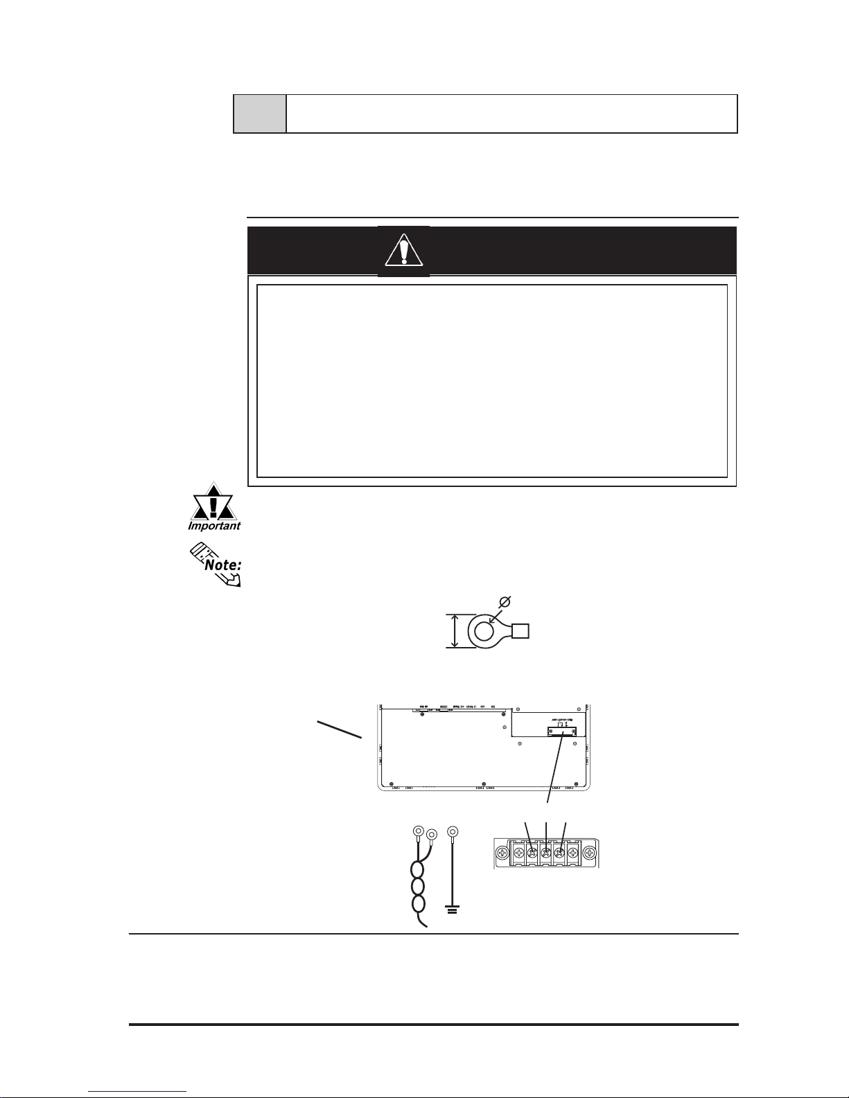
• Use thick wire (2 mm2 max.) for the FP's power cable. Be sure that the cable is
twisted near the ring terminals.
• Use ring terminals with the following dimensions:
3.2 mm
less than 6.0 mm
3-2 Wiring
This section describes wiring installation precautions and the FP's power cord
wiring procedure.
3-2-1 Power Cord Connection Precautions
When the frame ground (FG) terminal is not connected, the FP is easily
affected by noise interference. Be sure to ground the unit.
• T o pr event the power terminals from being short-circuited due to a loose screw,
use ring terminals with insulating sleeves.
Rear of FP
LNFGLN
FG
Ring terminal *1
Power input
terminal block
*1 L = Live line for AC input
N = Neutral line for AC input
FG = Ground terminal to be connected to the FP housing
Recommended ring terminal: V2-MS3 or equivalent
(Manufactured by JST Co.)
• When connecting the power cord, be sure that power
is not supplied to the FP due to the danger of electric shock.
• If a voltage exceeding the FP's specified power range
is applied, both the FP and the power supply units
will be damaged.
• Since the FP has no power switch, set up a separate
circuit breaker.
WARNINGS
Page 33

FP-790T User Manual3-6
Installation and Wiring
1) Connect the FP's power cord to the main power supply.
2) Check to make sure the FP's power cord is disconnected from the main
power supply.
3) Remove the terminal block's transparent cover.
4) Remove the screws from the 3 middle terminals, align the ring terminals
and re-attach the screws. (Check that each wire is securely connected)
5) Replace the terminal block's transparent plastic cover.
Use no more than 0.5~0.6N•m of torque to tighten the screws.
3-2-2 FP Power Cord Connection Procedure
Page 34
FP-790T User Manual 3-7
Installation and Wiring
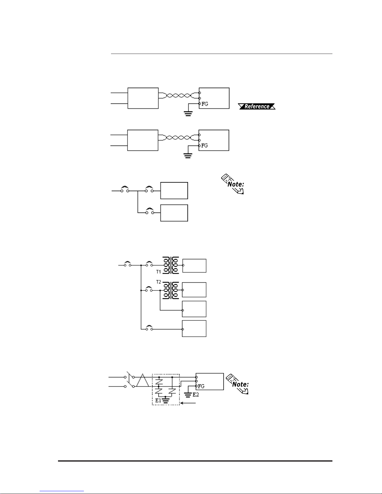
• Be sure the surge absorber
(E1) is grounded separately
from the FP (E2).
• Select a surge absorber that
has a maximum circuit
voltage greater than the
power supply's peak voltage.
3-2-3 FP Power Supply Connection Procedures
Please pay special attention to the following points when connecting the power
cable to the FP-790T's Terminal Block.
• Between the line and ground, select a power supply that is low in
noise. If there is an excessive
amount of noise, connect a noise
reducing transformer.
Use Voltage and Noise Reducing transformers with capacities in excess of 100VA .
• When supplying power to the FP,
separate the power input/output
and operation signal lines as shown
in figure 3.
• To increase the FP's noise resistance,
twist the power cable before con-
• If the voltage supplied exceeds the
FP's designated range, connect a
voltage transformer.
Chapter 2, "Speci-
fications", for the allowable voltage range.
necting it to the FP.
• The power cord must not be bundled or kept close to the main circuit lines (high voltage, high current), or input/output signal lines.
• Connect a surge absorber, as shown
in the diagram, to deal with power
surges.
• To prevent noise, make the power
cord as short as possible.
power
input/output
power
input/output
FP
Twisted
Lines
Twisted
Lines
isolating
transformer
FP
main
power
FP
power
FP
input/output
unit
main
power
FP
power
FP
constant
voltage
transformer
Input/ Output Unit
Input/ Output Unit
Operation
Unit
main circuit
FP
surge
absorber
Fig.1
Fig.2
Fig.3
Fig.4
Fig.5
Page 35
FP-790T User Manual3-8
Installation and Wiring
3-2-5 FP Input/Output Signal Line Cautions
Input and output signal lines must be separated from power cables.
If this is not possible, use a shielded cable and connect the shield to the FP
chassis.
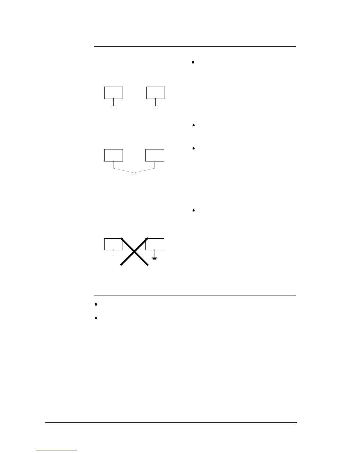
3-2-4 FP Grounding Cautions
other
equipment
(a) Exclusive grounding (BEST)
(b) Common grounding (OK)
If exclusive grounding is not possible, use a common grounding point.
The grounding wire should have a
cross section larger than 2mm2. Make
the connection point as close to the
FP as possible, and make the wire as
short as possible. When using a long
grounding wire, use a thicker wire
placed in a duct.
If the FP does not function properly
when grounded this way, disconnect
the ground wire from the FP's FG terminal.
Connect the FP's FG terminal to an
exclusive ground. [Grounding
resistance of under 100Ω.]
FP
other
equipment
FP
FP
other
equipment
(c) Common grounding (BAD)
Page 36
FP-790T User Manual 3-9
Installation and Wiring
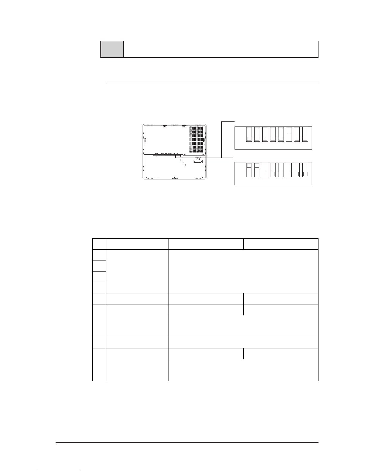
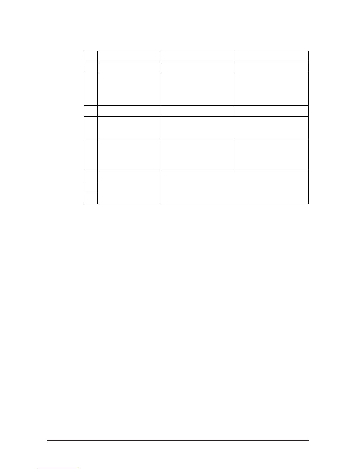
The setup switches (dip-switches) are located in the rear of the FP.
Dip-Switch (SW2)
3-3-1 Operation Mode Setup and Adjustment
3-3 Setup of Operation Mode and Positioning of Display
Prior to shipment, the FP's DIP switches have been set as shown above. These 8
bit DIP switches control the items listed below:
FP-790T (rear view)
Dip-Switch (SW1)
1 2 3 4 5 6 7 8
OFF
Ð
1 2 3 4 5 6 7 8OFF
Ð
Dip Switch 1
No. Function OFF ON
1
2
3
4
5 Screen Display Setting Normal Mode OSD St ar t ing U p
OFF when stat ing up ON when st at ing u p
7Reserved
OFF ON
Reserved Set this switch to OFF
Choose t o turn backlight s ON w hen s t ar ting up, or k eep OFFBacklight Setting
Default s ett ing), choose whether ba cklight OFF or not .
8 Aut omat ic Backlight OFF
6
Set this switch to OFF
When no t op erating t he unit f or a s pecific period of time (5 min.
until operating the unit
Page 37
FP-790T User Manual3-10
Installation and Wiring
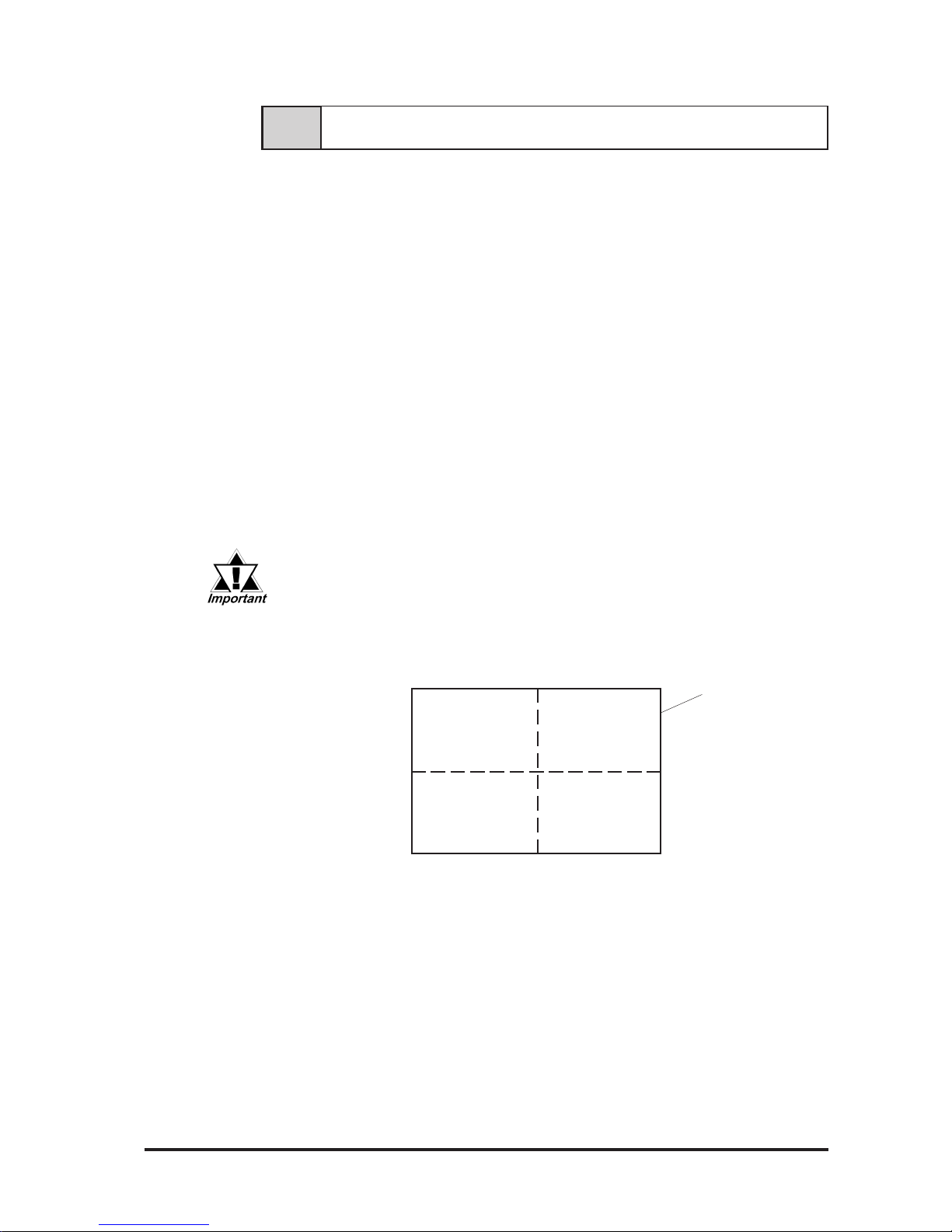
Dip Switch 2
*1 A menu display disappears after about 10 seconds, and when touching SELECT
area (screen's lower left corner), the menu display reappears.
No. Function OFF ON
1 External Mouse Inter face NO YES
Touch Data
Transmission Mode
Selection
3 Touch and click sound ON OFF
Touch Panel Calibration
Setting
6
7
8
2 (Reser ved) (RS232C w hen in us e)
4 Set this switch to OFF
5
Screen Setting Mode
Switch
*1
Reserved Set this switch to OFF
Screen Setting Mode
(tur n OFF when adjust ing the
screen)
Normal Mode
Page 38
FP-790T User Manual 3-11
Installation and Wiring
3-4 Screen Adjustment using OSD
Use the OSD (On Screen Display) to adjust the following items:
1) Brightness 2) Contrast 3) Horizontal Size Adjustment 4) Phase Adjustment
5) Horizontal Display Position 6) V ertical Display Position 7)All Reset (Default)
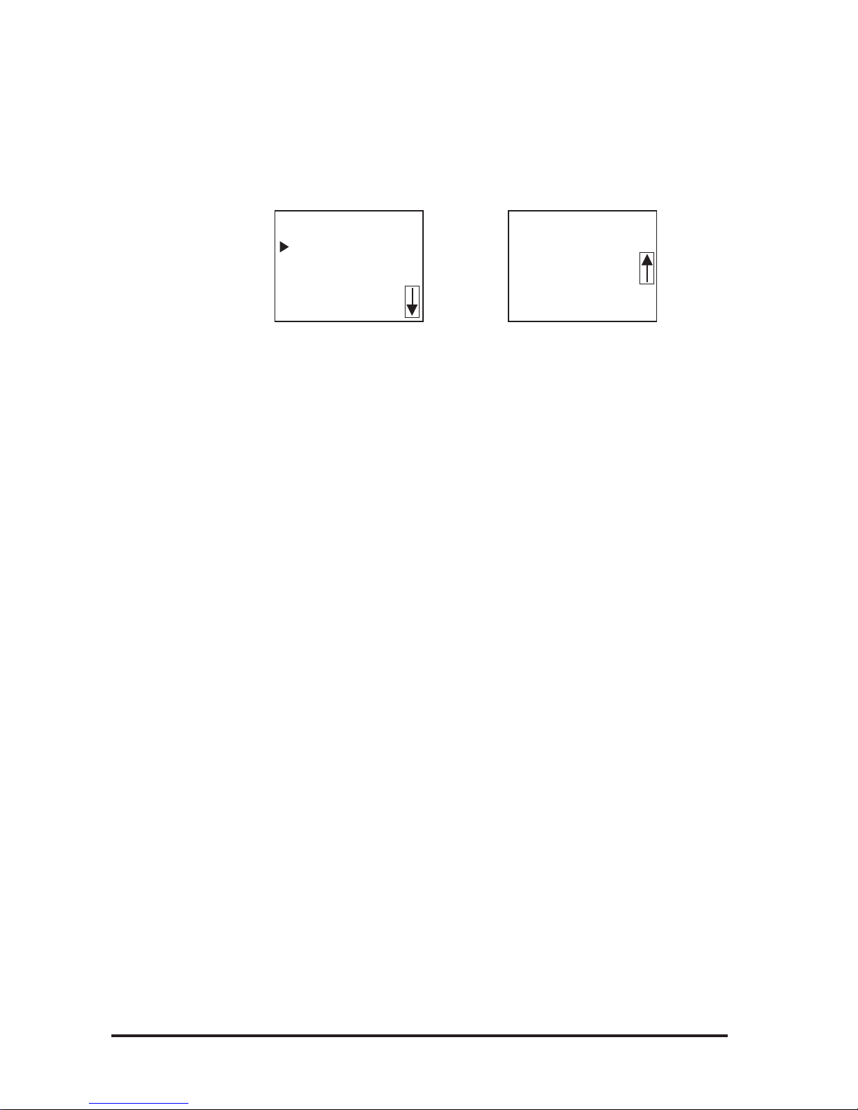
OSD Start Up by touching a panel (When DIPSW2-5 are OFF.)
Touching the left upper corner, right upper corner, and right lower corner of
the touch panel within 5 seconds, will start up the OSD. Touching the left
lower corner within 5 seconds, will also start up the OSD.
OSD Start Up by dip switches (When DIPSW2-5 are ON.)
Touching the left lower corner of the touch panel, will start up the OSD.
To exit Adjusting mode, turn DIPSW1-5 OFF.
How to Quit
T o quit the OSD automatically , do not touch the touch panel for approximately
5 seconds.
• The effective range area for each corner is 1/10 the length of the
panel.
• Since touch panel input data is used for OSD screen adjustment
until quitting the OSD, regular input data will not output from the
FP.
FP Display
Panel
DOWN/LEFT UP/RIGHT
SELECT
EXIT
(return to
previous step)
DOWN/LEFT Used to increase /decrease the value of each setting item, or
used to move downward when selecting an item in Menu mode.
UP/RIGHT Used to increase /decrease the value of each setting item, or
used to move upward when selecting an item in Menu mode.
SELECT Used to select each setting item in the OSD menu.
EXIT When EXIT is pressed, the changed value is saved, and the
previous menu is displayed.
Page 39
FP-790T User Manual3-12
Installation and Wiring
Auto Adjust Adjust all the adjustment items.
Brightness Adjust the brightness.
Clock Adjust the dot clock frequency.
Position Adjust the horizontal and vertical positions.
Contrast Adjust the contrast
Color Level Adjust RGB colors and white balance.
Information Displays the current screen settings.
OSD Position Used to adjust OSD display position.
All Reset Reset all the setting data.
To perform display adjustments, follow the procedures given below:
1) Turn OSD (Main Menu) ON.
2) Use the [DOWN/LEFT] or [UP/RIGHT] switches to choose one of the
adjustment items.
3) Press the [SELECT] switch to select a desired item, and that item's adjustment
screen will be called up.
4) Use the [DOWN/LEFT] or [UP/RIGHT] switches to change the value of the
selected item.
5) Press the [EXIT] switch to return to the OSD menu. (Control will return to
the OSD menu after 5 seconds when no panel operation is performed.)
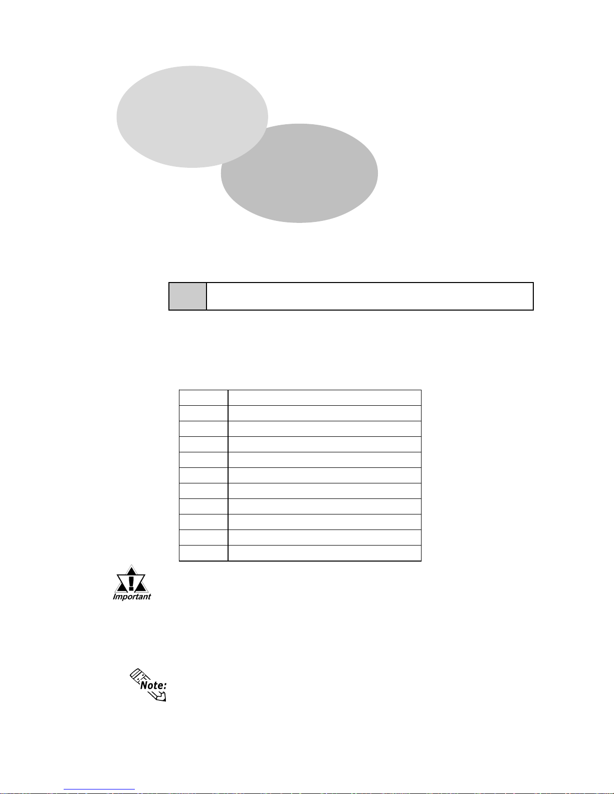
Adjustment Menu
This area displays the FP's adjustment menu. Every time you press this switch,
the On Screen Display toggles between ON and OFF , and when one of adjustment
items is selected and the switch is pressed, an adjustment screen will be called
up.
Auto Adjust
Brightness
Clock
Position
Contrast
Color Level
Information
OSD Position
All Reset
MENU MENU
Page 40
FP-790T User Manual 4-1
4-1 Command List
This section describes the serial commands available with the FP (command
transmission from the host (PC) to the touch panel (FP)).
Chapter 4
Touch Panel Commands
1. Command List 3. Boot-up Initialization
2. T ouch Panel Data Input
All data and command codes are expressed in hexadecimal numbers. (Example:
65h = 65HEX)
<Serial Command List>
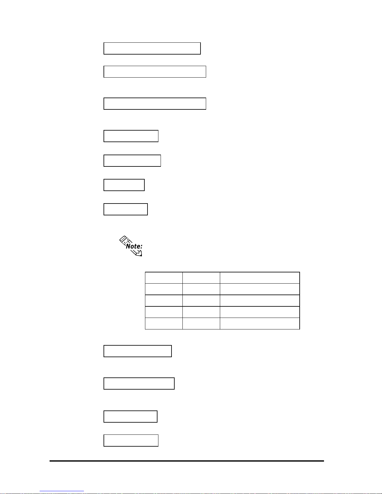
Code Function
65h Turns on the backlight.
67h Turns off t he backlight . ( Automatic reset)
69h Turns on t he click sound.
6Ah Turns of f the click sound.
71h Turns on the buzzer.
72h Turns of f the buzzer .
73h Turns on calibration mode.
74h Turns of f calibration mode.
75h Turns on t ouch panel dat a output.
76h Turns of f touch panel dat a output.
• All codes other than those shown here are reserved. These commands should never be issued when using the FP.
• The above commands cannot be used with the FP-ME000 Touch Panel
Driver (Mouse Emulator) or the English version of the U-TP (Gunze
Corporation) software. For details, contact your local Pro-face representative.
Page 41
Touch Panel Commands
4-2 FP-790T User Manual
Calibration mode ON 73h
Starts touch panel calibration mode. (Same function as when SW1-5 is
ON.)
Calibration mode OFF 74h
Ends touch panel calibration mode. (Same function as when SW1-5 is
OFF.)
Touch data ON 75h
Enables touch panel data output.
Touch data OFF 76h
Disables touch panel data output.
Buzzer Click Status
ON ON Bu zz e r O N
ON OFF Buzze r O N
OFF ON Click sound ON
OFF OFF Buzzer and click sound OFF
Priority is given to buzzer output over the click sound. Thus, when
both the buzzer output and click sound are set to ON, the buzzer
output is activated.
Backlight ON (High brightness) 65h
Turns on the backlight at high brightness.
Backlight OFF (Automatic reset) 67h
Turns off the backlight. When either SIO communication or touch
operation is performed, the backlight is turned on.
Backlight OFF (Command reset) 68h
Turns off the backlight. After a dif ferent serial command (e.g. 65h, 66h) is
received, the backlight is turned on.
Click sound ON 69h
Every time you touch the display panel a click will sound.
Click sound OFF 6Ah
Turns off the click sound.
Buzzer ON 71h
Turns on the buzzer output
Buzzer OFF 72h
Turns off the buzzer output.
Page 42
Touch Panel Commands
4-3FP-790T User Manual
4-2 Touch Panel Data Input
The following describes how to connect an RS-232C cable and send FP touch
panel data to the host.
RS-232C connection (When SW1-1 is OFF)
Coordinate output data sent from the FP to the host is not exactly equal to the
coordinates used on the display device. Therefore, an I/F program is necessary
to convert the coordinates on the touch panel into those used on the display
device. It is also necessary to calibrate individual panel differences, depending
on the touch panel used.
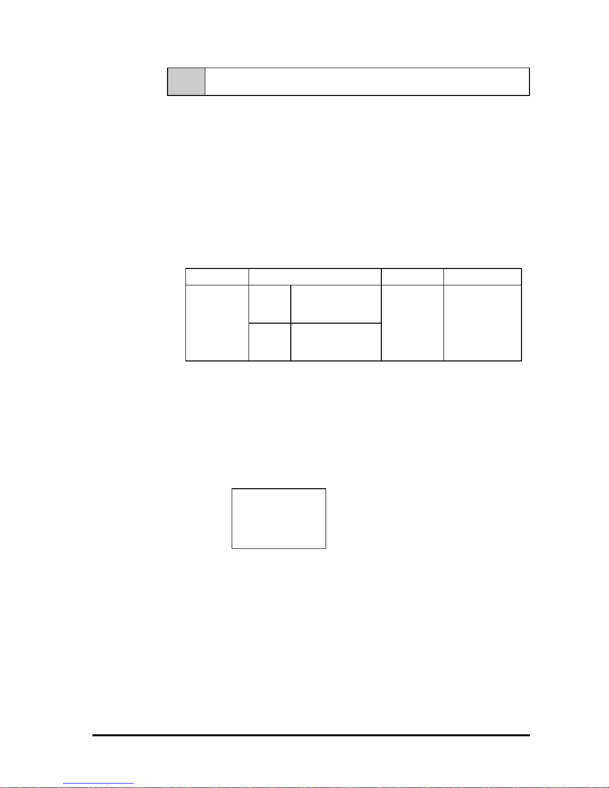
The mouse emulation software listed below can automatically convert the
coordinates with simple initial settings.
A separate conversion program is required when using a different OS. To create
a conversion program for a different OS, please observe the following
instructions:
(1) Resolution
The FP has “1024” resolution in both the X and Y axes. The origin point (0,0) is
in the upper right corner.
(0,0)
(1023,1023)
OS Calibrat ion Application
Using
Japanese
OS
FP-790 Mouse Emulator
for Windows FP-ME000
(made by Digital Corp.)
Using
English
OS
English version of
U-TP Touch Panel
Driver(Gu nze C o rp.)
I/F program
Windows
®
95
Windows
®
98
Windows NT
®
Windows® 2000
Performed
by internal
program.
FIX-32 (PC data
management
software package)
(Intellution Corp.), or
similar application.
Page 43
Touch Panel Commands
4-4 FP-790T User Manual
(2) Data Format
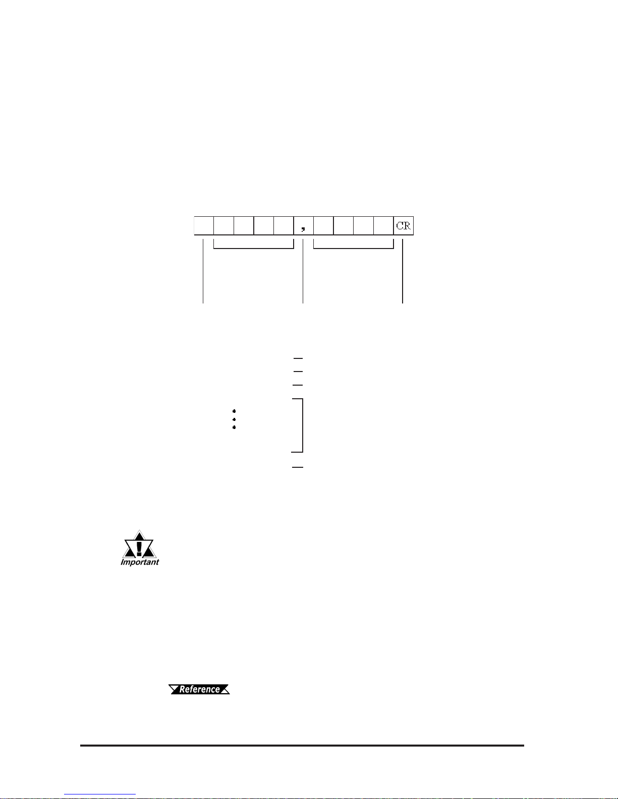
All data is in 8-bit ASCII format, and is structured in the following 11 byte
strings.
Header: 1 byte (T = touched; R = released)
X coordinate: 4 bytes (0000 ~ 1023)
Separator: 1 byte (,)
Y coordinate: 4 bytes (0000 ~ 1023)
Termination code: 1 byte (CR = 0Dh)
X coordinate Y coordinate
31h ('0') ~ 39h ('9')
four digits
31h ('0') ~ 39h ('9')
four digits
54h ('T') : T ouched
52h ('R') : Released
2Ch (',') : fixed 0Dh ('\n') : fixed
<Example>If the coordinate (X=23, Y=500) is touched.
T0023, 0500CR touched
T0023, 0500CR continuous output at the same location
T0024, 0500CR moving the finger without releasing touch
T0024, 0499CR
continuous data output unless finger is released
T0022, 0501CR
T0023, 0500CR
R0023, 0500CR when released, only 1 unit of data is sent
(3) Sampling Rate
A maximum of 87 points per second.
(4) Cable Connection
Connect the RS-232C connector provided at the rear of the FP to the host’s
serial interface through the optional SIO cable.
Chapter 1 Introduction
Connect the host (PLC) data cable to the FP's rear-mounted RS-232C connector.
(Digital's optional SIO cable is recommended)
The PL's touch panel provides a resolution of “1024” (10 bit). However,
the resolution of the actual output data is only 20 to 990 (approx.).
Therefore, all the coordinates of the pixels on the horizontal axis cannot
be detected. According to this calculation, the FP's output data includes
coordinates that cannot be displayed, since the touch panel is larger
than the display device.
Page 44
Touch Panel Commands
4-5FP-790T User Manual
4-3 Boot-up Initialization
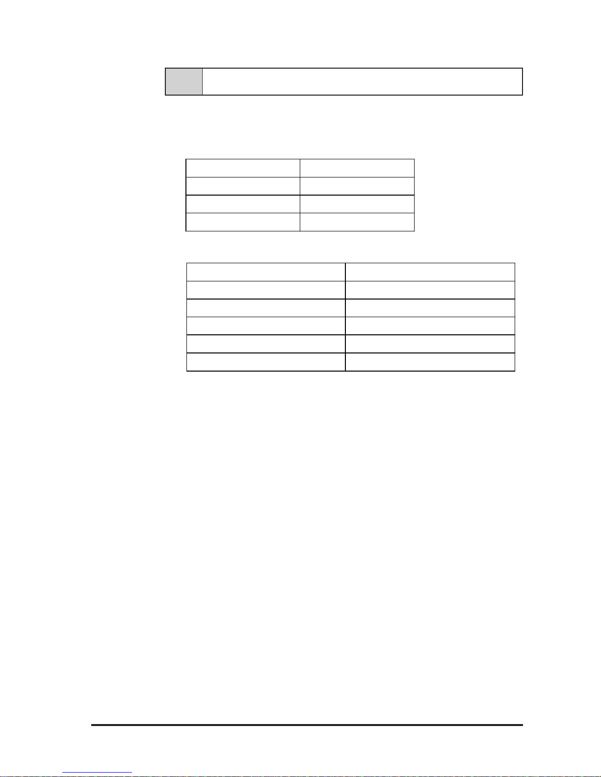
When the power is turned ON, the touch panel is initialized as follows.
• Clears its internal buffer .
• Initializes the serial communication mode.
• Initializes the system default values.
Baud r ate 9600bps
Dat a lengt h 8 bits
Parity None
St op bit 1 bit
Function Def a ult s e tting
Backlight ON
Backlight condition ON
Click sound ON
Buzzer OFF
Touch panel data out p ut ON
Page 45

4-6 FP-790T User Manual
MEMO
Page 46
This section assumes that the FP is the cause of a
problem, not the host (PLC). When the host is the problem,
please refer to that device's manual.
Chapter 5
Troubleshooting
1. Troubleshooting
FP-790T User Manual 5-1
W arning
5-1 Troubleshooting
5-1-1 Possible Device Problems
Two possible types of trouble are as follows.
• No display
- No display appears after the unit is switched on.
- The screen disappears during RUN mode.
- The screen display is not normal.
• Touch panel doesn't respond
The touch panel does not react when pressed, or its reaction time is
abnormally slow.
• Because of the danger of an electric shock, be sure
the power cord is not connected when wiring the
unit.
• When changing the backlight, since there is a danger of an electric shock or burn, be sure to turn the
FP off and wear gloves.
WARNINGS
Troubleshooting procedures for these problems are described in the flowcharts
on the following pages.
Page 47
FP-790T User Manual
Troubleshooting
5-2
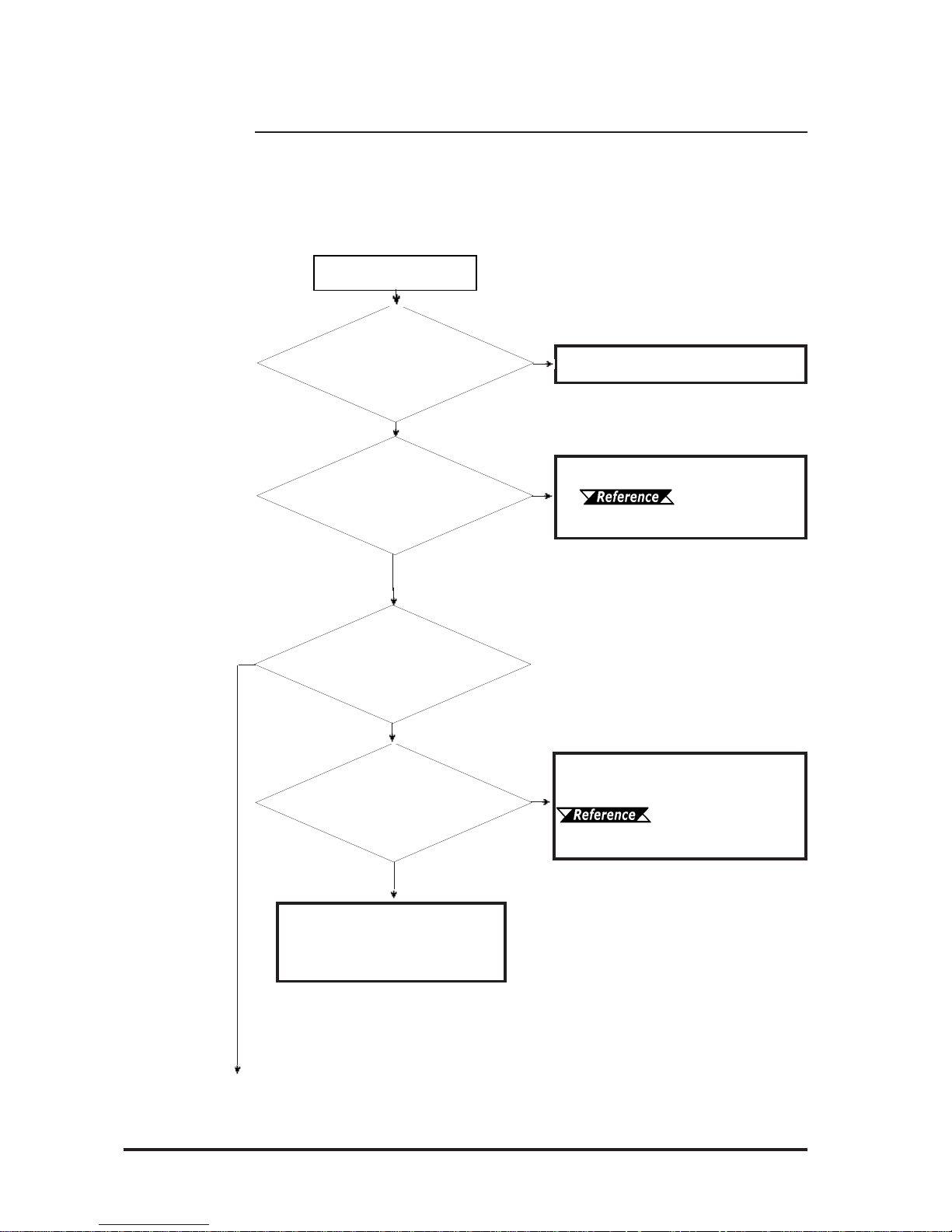
When the screen does not display when powering up, or if the screen turns OFF
by itself, use the flowchart below to find an appropriate solution.
5-1-2 No Display
No Screen Display
YES
Is the FP turned ON?
YES
NO
NO
NO
YES
Is the FP's RGB cable
correctly connected?
Is the FP's backlight
(CFL) working
correctly? (turned ON?)
Even though the display
isn't perfect, does an image
appear?
There is a problem with the FP.
Please contact your local FP
distributor.
NO
YES
Connect the cable as designated.
Chapter 2-4
Option Cable Pin Numbers
Correct the screen coordinate
positioning.
3-3 Run Mode and
Display Position Settings
Please turn the FP ON.
Page 48
FP-790T User Manual 5-3
Troubleshooting
YES
YES
NO
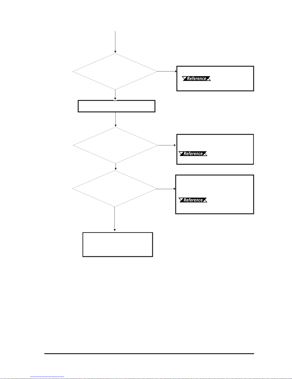
Is the correct voltage being
used?
Adjust the voltage being supplied.
Chapter 2 -
Specifications
NO
Is the power cable
connected correctly to the
FP?
Have the FP's backlights
been set up correctly?
NO
YES
Check that the FP's backlights are
correctly connected and change
them if required.
6-3 Changing the
Backlight
There is a problem with the FP.
Please contact your local FP
distributor.
Connect the power cable
correctly.
Chapter 3 -
Installation and Wiring
Turn OFF the FP
Page 49
FP-790T User Manual
Troubleshooting
5-4
• To use the SIO connection mode, a touch panel communication program is
required.
• To use the mouse connection mode, it is necessary to set up the PS/2 mouse
driver included in your OS.
5-1-3 The Touch Panel Does Not Respond
YES
NO
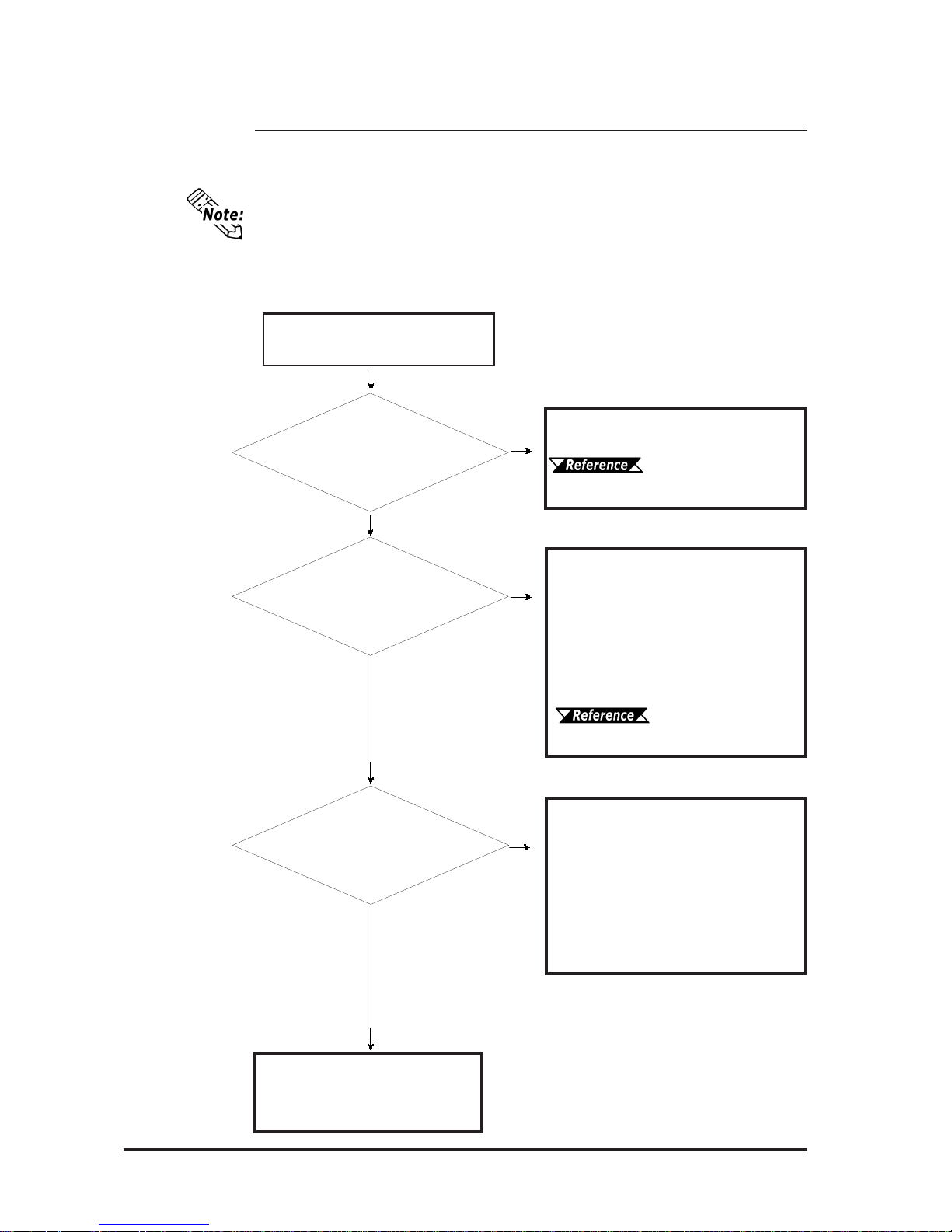
When the touch panel does not react to your touch, use the flowchart below to
find the origin of the problem and the appropriate solution.
The touch panel does not
respond.
YES
Are all connection settings
and dip switches correct ?
Set the DIP switches at the rear of
the FP correctly .
3-3 Setup of Operation
Mode and Positioning of Display
Does the connected cable
conform to the settings ?
YES
NO
Connect the cable according to the
connection method specified by the
DIP switches.
For the SIO connection, connect the
SIO cable.
For the mouse connection, connect
the mouse/keyboard cable.
1-1 Connecting the
FP to a PC
Has the necessary
software been
properly set up?
Set up the software necessary for the
specified communication.
For the SIO connection, set up the
touch panel communication
program.
For the mouse connection, set up the
PS/2 mouse driver included in your
OS.
NO
YES
There is a problem with the FP.
Please contact your local FP
distributor.
Page 50
6-1FP-790T User Manual
Chapter 6
Maintenance
1. Cleaning the FP's Display 3.Changing the Backlight
2. Periodic Check-up
This chapter describes the precautions and inspection procedures necessary to
ensure satisfactory FP performance.
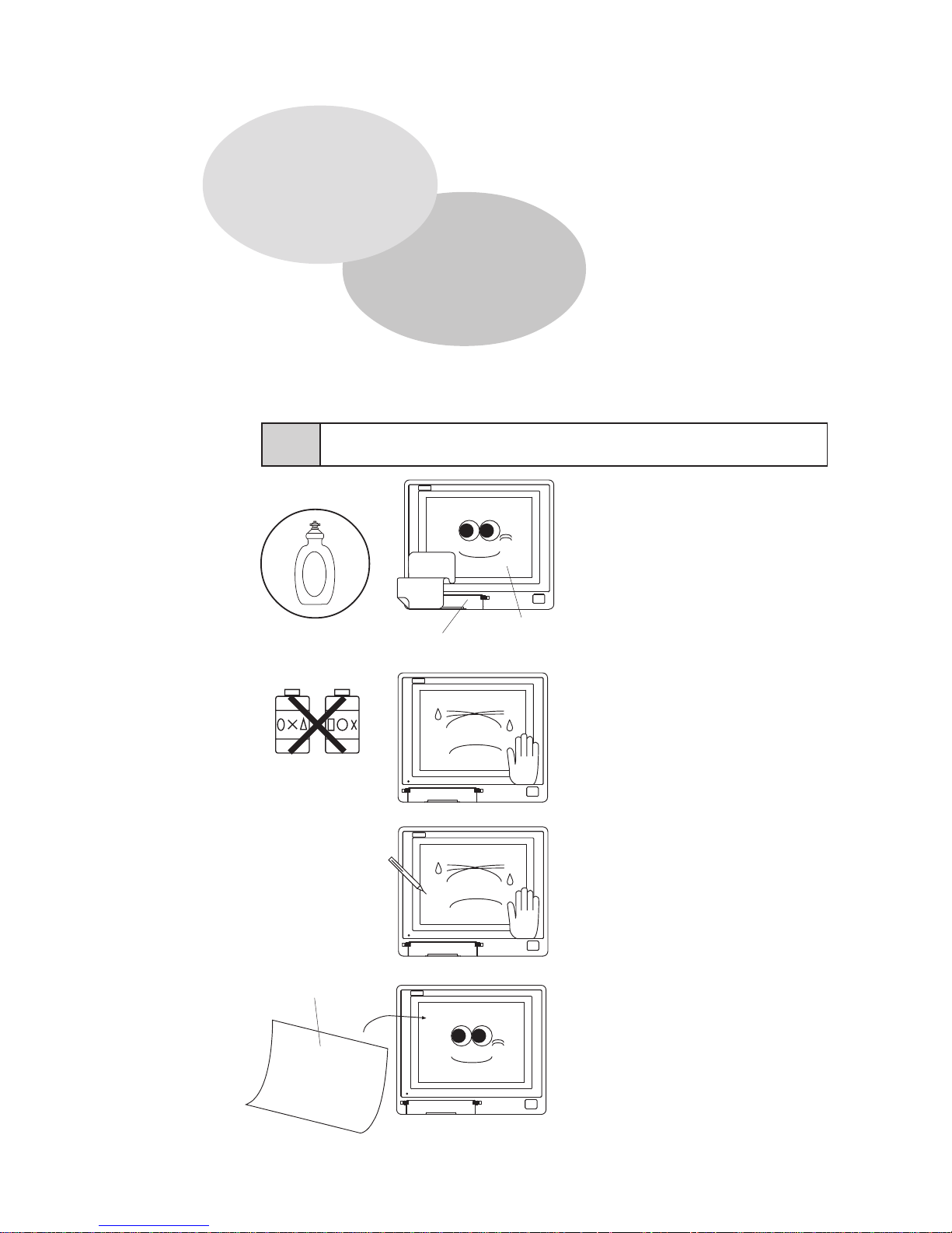
6-1 Cleaning the FP's Display
OK!
Neutral detergent
Maintenance
Cover
Screen
When the FP's display or case
becomes dirty, use a neutral
detergent applied to a damp soft
cloth to clean the surface.
NO!
Paint thinner
Organic solvent
Acidic agents
Do not use paint thinner, organic
solvents, or highly-acidic agents to
clean the unit.
Do not press the touch panel display
with sharp objects, such as a
mechanical pencil; otherwise, the
display may be damaged.
Protection sheet
Attach the protection sheet when
using the FP in a harsh environment.
Page 51
Maintenance
6-2 FP-790T User Manual
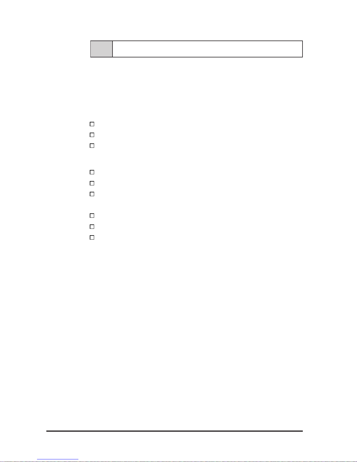
T o maintain your FP in its best condition, please check the unit periodically.
Inspection Items:
( When the FP is mounted into a cabinet, the conditions inside the cabinet
are considered to be the environment )
Surrounding Environment
Is the surrounding temperature within the allowable range? (0°C~40°C)
Is the humidity within the specified range? (30% RH~85% RH)
Is the atmosphere free of corrosive gas?
Electrical Specifications
Is the input voltage appropriate? (AC85V TO AC265V)
Is the power supply voltage stable ?
Is the power supply frequency correct (50/60 Hz) ?
Attachments
Is the cable connected properly? Is it loose?
Are the mounting brackets holding the unit securely?
Are there many scratches, cuts or traces of dirt on the installation gasket?
6-2 Periodic Check-Up
Page 52
Maintenance
FP-790T User Manual 6-3
Replace the backlight according to the procedure below . (The following explanation
assumes that the FP has already been removed from the panel)
6-3 Changing the Backlight
• Be sure the FP's power cord has been disconnected prior to
changing the backlight. When the FP's power cord is connected
and the FP is ON, high voltage runs through the wires in the
backlight area. Do not touch them!
• When the FP's power cord has just been disconnected, the backlight area is still very hot! Be sure to wear gloves to prevent being burned.
• The backlight is very fragile. Do not touch the glass tube directly
or try to remove its power cord. If the glass tube breaks you may
be injured.
Warning
• During replacement, be sure to protect the front surface of the FP’s
display so that it is not scratched or damaged.
• The FP has both an upper and a lower backlight bulb. Be sure to
replace both at the same time.
• Since CFL is used for the backlights, they should be disposed of in
a manner appropriate to your local government’s laws or
regulations.
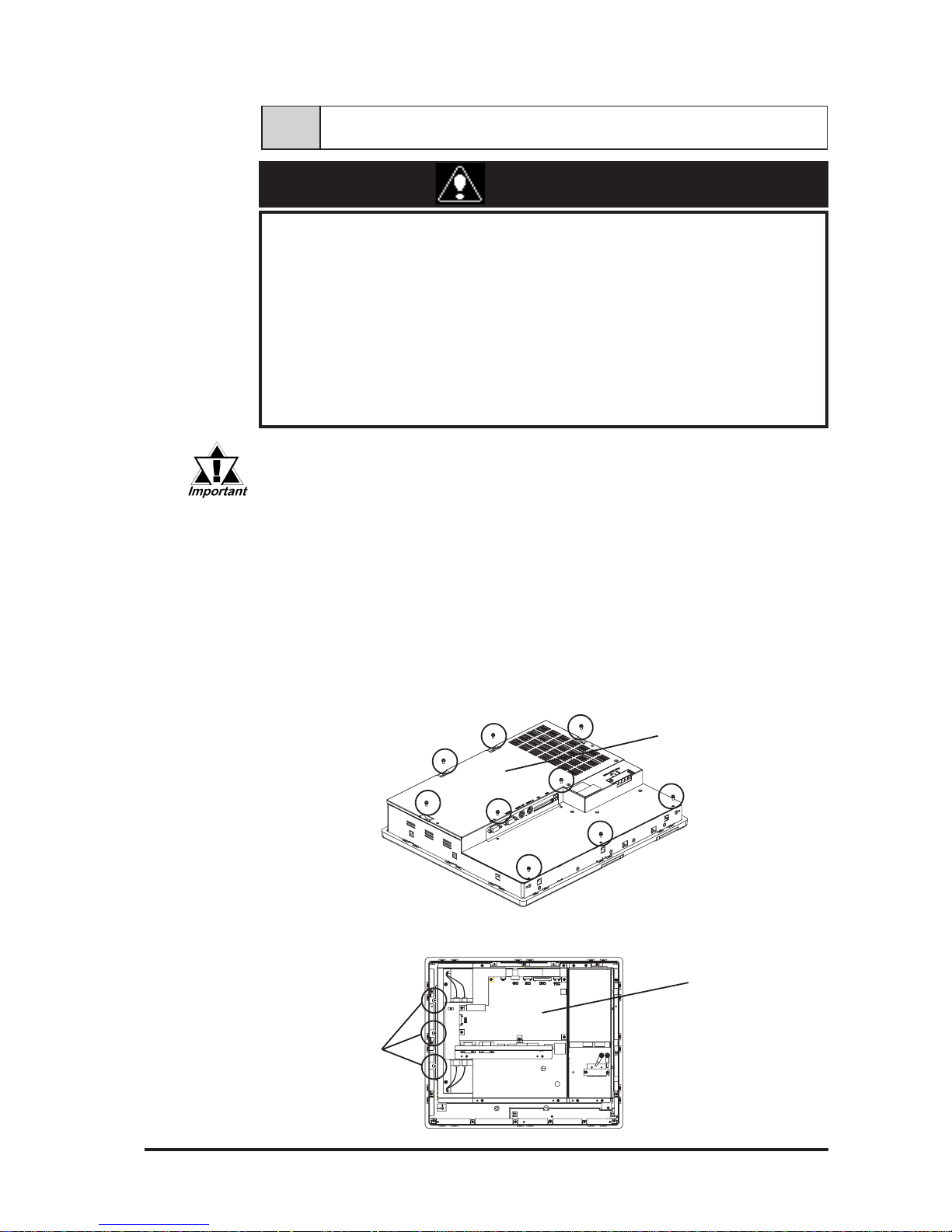
Inner unit
Inner unit
attachment
screws
1) Place the FP on a flat worktable with the front panel facing down.
2) Loosen the nine (9) rear cover attachment screws, and remove the rear
cover.
Rear cover
3) Remove the three (3) inner unit attachment screws.
Page 53
Maintenance
6-4 FP-790T User Manual
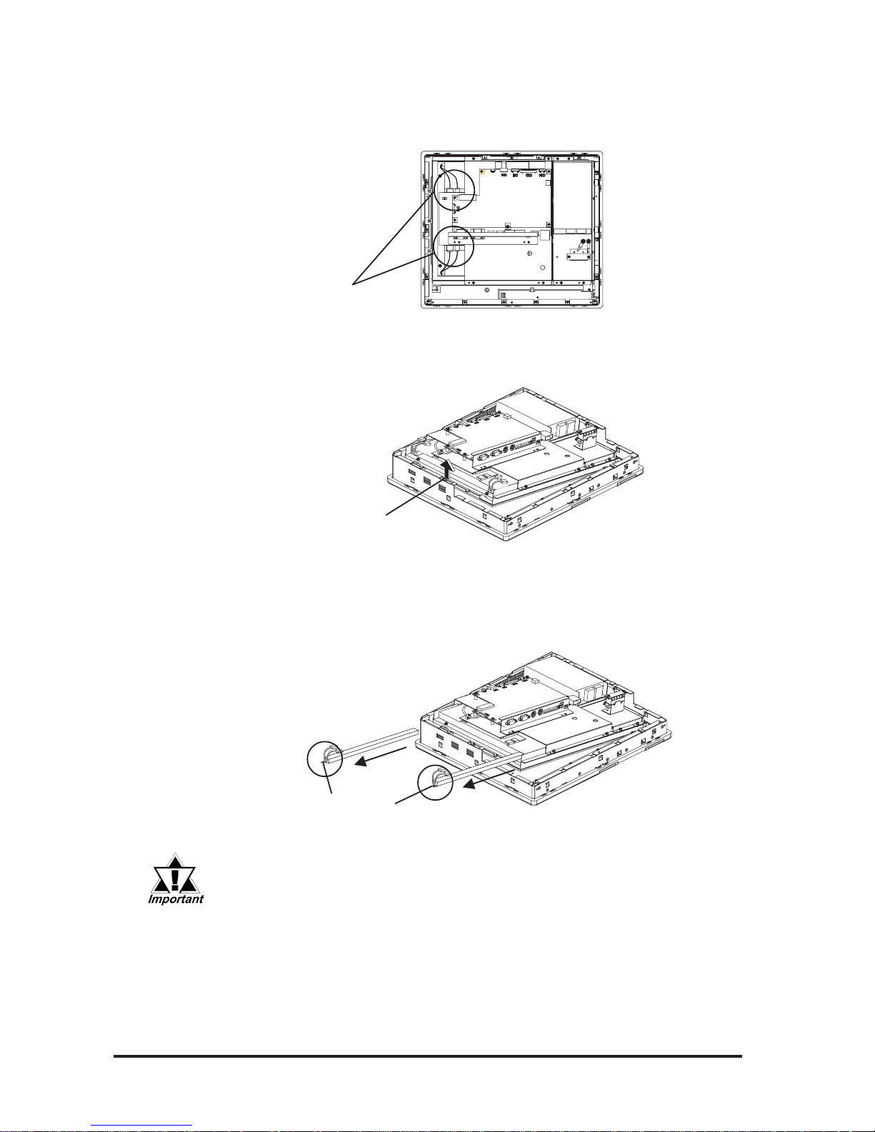
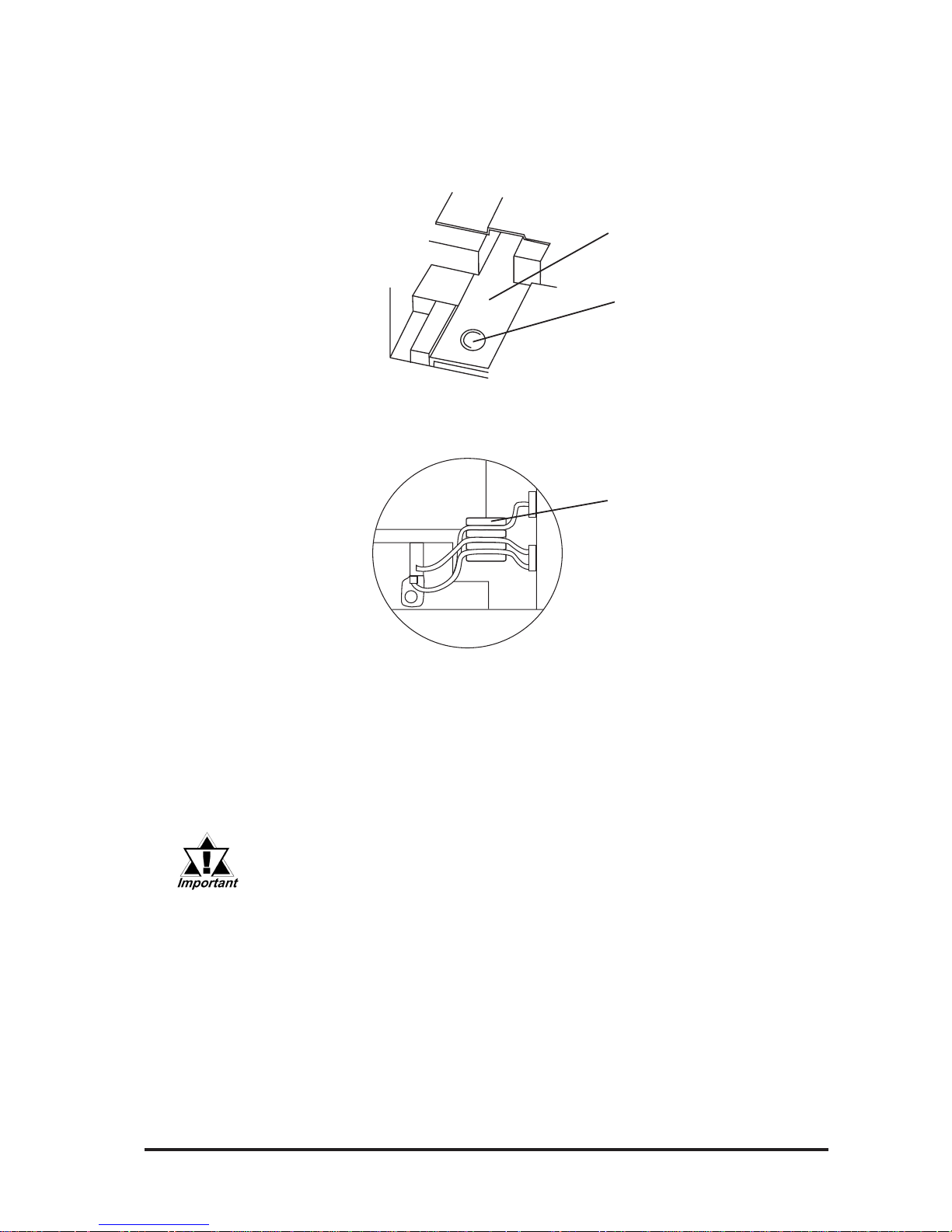
Backlight
power
connectors
Lift up the inner unit
4) Free the backlight power cables from the cable clamps, and detach the
four (4) backlight power connectors that connect the backlights to the
inverter.
5) Lift up and hold one side of the inner unit (left or right).
6) Carefully bend each backlight’s Positioning Tab upwards until it is clear
of the Positioning Pin. Then, slowly pull out each backlight horizontally
from its holder.
Positioning T ab
• Be sure to pull out the backlights gently if they become stuck in
their holders, or they can be damaged.
• When pulling out the backlight and holding the Positioning Tab, be
sure not to cut or pinch your fingers.
Page 54
Maintenance
FP-790T User Manual 6-5
Attach Replacement Backlight
1) Insert each replacement backlight completely into its holder, until the
Positioning Tab’s hole is over the Positioning Pin.
2) Secure each backlight cable in place by inserting it into its Cable
Clamp.
3) Connect all four (4) backlight power connectors.
4) Replace all three (3) inner unit attachment screws to secure the inner
unit in place.
5) Reattach the rear cover, and replace the nine (9) rear cover
attachment screws.
Positioning Tab
Positioning Pin
Cable Clamp
• Be sure not to pinch or cut any of the FP unit's internal wiring
when closing the rear cover.
• If any of the attachment screws becomes misplaced, check to be
sure that they have not fallen inside the FP. If a screw has fallen
inside the FP, do not connect the FP unit’s power cord until the
screw has been removed.
After changing the backlight, be sure to check that your FP display
operates correctly. If a problem occurs, contact your local FP distributor.
Page 55

6-6 FP-790T User Manual
MEMO
Page 56

FP-790T User Manual i
Index
A
Analog RGB Interface (RGB IN) .......................... 2-3
B
Boot-up Initialization .............................................4-5
C
CE Marking Notes ..................................................vii
Changing the Backlight ..........................................7-3
Cleaning the FP's Display ....................................... 7-1
Connecting the FP to a PC .....................................1-1
E
Electrical Specifications ........................................2-1
Environmental Specifications ................................ 2-2
Essential Safety Precautions ..................................... ii
External Dimensions ..............................................2-9
F
FP Grounding Cautions .........................................3-7
FP Input/Output Signal Line Cautions ...................3-7
FP Power Cable Connection Procedure .................3-5
FP Power Supply Connection Procedures .............3-6
FP-790T Features .................................................. viii
Functional Specifications .......................................2-2
H
Host Interface for Mouse (MOUSE OUT) ............ 2-5
I
Installation Fasteners ...........................................2-10
Installation Procedures ..........................................3-1
M
Mouse Interface (MOUSE IN) ..............................2-5
Mouse/Keyboard cable pin numbers .....................2-7
O
Optional Equipment ...............................................1-3
Optional Maintenance Parts ...................................1-2
Optional Parts ........................................................1-2
P
Package Contents ..................................................... ix
Panel Cut Dimensions .......................................... 2-10
Parts Names and Functions ....................................2-8
PC Connection Notes .............................................. vii
Periodic Check-Up ................................................7-2
Pin Assignments and
Signal Names for Serial Interf ......................2-4
Pin Connections for the SIO Interface Cable .........2-7
Power Cable Connection Precautions ....................3-4
R
RGB Interface Cable Pin Assignments ..................2-6
S
Screen Adjustment using OSD ............................ 3-10
Serial Command List .............................................4-1
Serial Interface (RS232C) .....................................2-4
Setup of Operation Mode
and Positioning of Display ..................... 3-8
Structual Specifications .........................................2-1
Symbol Information .................................................. x
T
Touch Panel Data Input .........................................4-3
Touch Panel Specifications ....................................2-2
Troubleshooting .....................................................6-1
Page 57

ii FP-790T User Manual
MEMO
 Loading...